مقارنة مصادر الليزر
الوسم بالليزر الليفي مقابل الليزر فوق البنفسجي: أيهما ينبغي أن تختار لمادتك؟
عادةً ما يكون الليزر الليفي أول ليزر يُختبر لأكواد المعادن الروتينية أو النقش الغائر. غالبًا ما يستحق الليزر فوق البنفسجي التجربة الأولى للوسم الدقيق على بلاستيكات مختارة حساسة للحرارة أو طلاءات رقيقة. القطعة الفعلية، وجودة العلامة، ومتطلبات الإنتاج تحدد النتيجة.
لا يُعد أي من المصدرين أفضل على نحو شامل. لا تختر بمجرد اسم المادة: تحقّق من العلامة المحددة، وحالة السطح، ومعايير القبول على عينات تمثيلية.
الليزر الليفي أم فوق البنفسجي: أي ليزر يجب أن تختبره أولاً؟
ابدأ بالمادة كما وردت، والتغيير الذي تحتاج إلى إجرائه على سطحها، ومقدار التغيير الذي يمكن أن تتحمله القطعة:
- الفولاذ المكشوف أو الفولاذ المقاوم للصدأ، والأرقام التسلسلية والرموز الصناعية النموذجية: اختبر الليزر الليفي أولاً، ثم تحقق من التباين وجودة الرمز ومتطلبات التشطيب.
- النقش على المعادن بعمق فيزيائي محدد: عادةً ما يكون ليزر الألياف هو التجربة الأولية الأكثر عملية، شريطة أن يكون التجويف الناتج والسطح المحيط مقبولين.
- البلاستيك المقولب الحساس للحرارة أو العلامات الدقيقة جدًا على الأسطح الهشة: اختبر الأشعة فوق البنفسجية مبكرًا، لكن افحص من الانصهار أو تغير اللون أو التشوه أو أي تغييرات غير مقبولة أخرى.
- البوليمرات المصبغة، والأجزاء المؤكسدة آنوديًا أو المطلية، والزجاج، وطبقات السطح المعقدة: تحقق من أي طبقة تمتص الطاقة وما الذي يجب أن يبقى سليمًا؛ قد يكون من الضروري إجراء تجربة جنبًا إلى جنب أو استخدام عملية أخرى.
هذه هي تجارب أولية, ، وليست استنتاجات حول أي آلة ستلبي متطلبات القبول لديك عند معدل الإنتاج المطلوب. لفهم الخيارات الأولية، انظر إلى كيفية استجابة السطح الفعلي لكل ليزر وإعداداته.
لماذا تنتج ليزرات الألياف والليزرات فوق البنفسجية نتائج وسم مختلفة؟
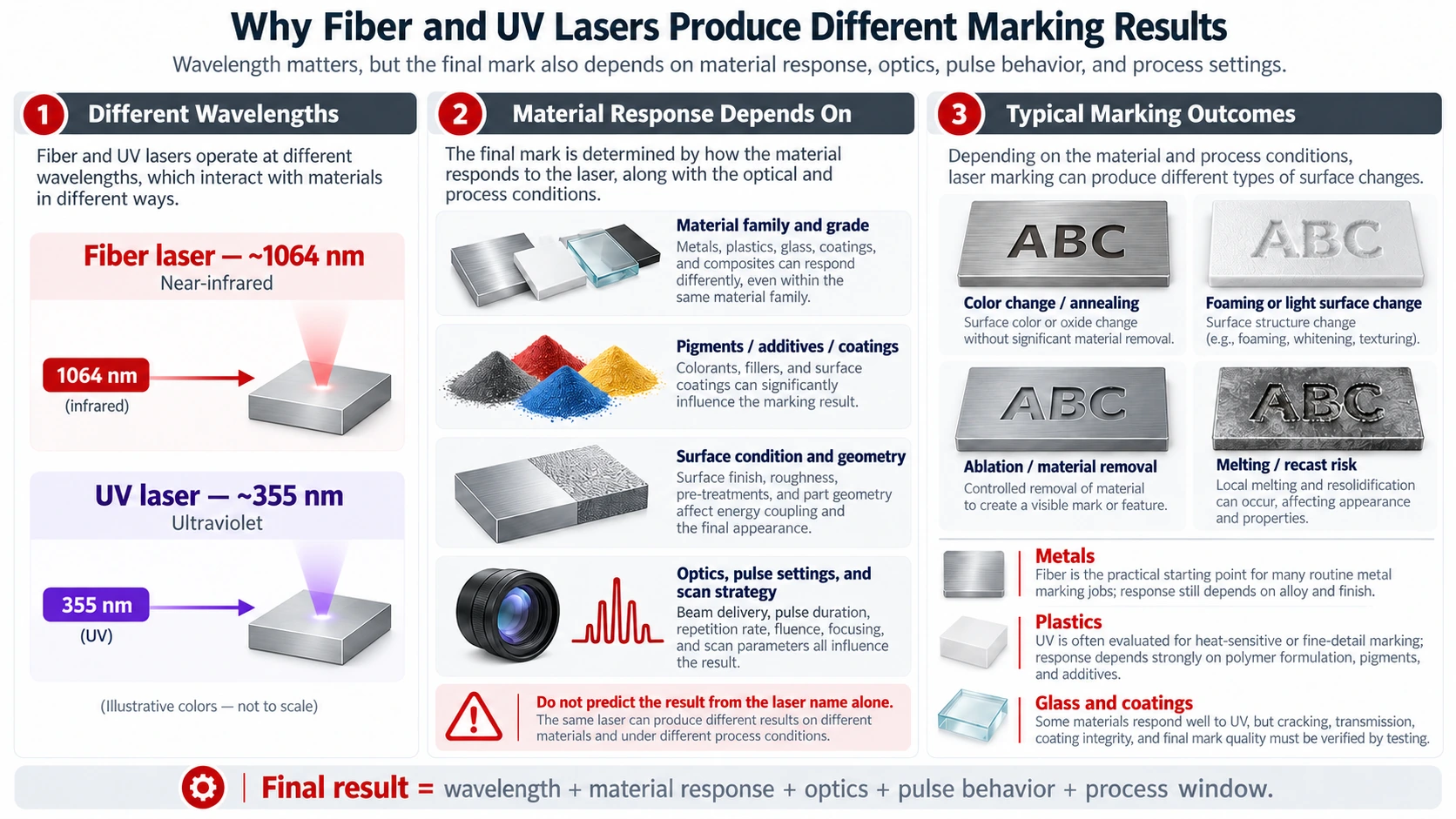
الأنظمة الصناعية التقليدية لوسم الألياف عادةً ما تصدر ضوءًا قريبًا من الأشعة تحت الحمراء حول 1.06–1.09 ميكرومتر، اعتمادًا على طراز المصدر. الأنظمة الصناعية الشائعة لوسم الأشعة فوق البنفسجية تعمل عند 355 نانومتر. يغيّر الطول الموجي كيفية اقتران الطاقة في قطعة العمل، لكن استجابة المادة تعتمد أيضًا على كيمياءها وتصبغها وحشواتها وطبقة الأكسيد والطلاءات. تشرح نظرة عامة على الوسم بالليزر من TRUMPF لماذا يمكن أن تنتج الأسطح وظروف المعالجة المختلفة آليات وسم مختلفة.
قد تكون النتيجة المطلوبة تغيّرًا في اللون أو في الأكسيد، أو تكوّن رغوة داخل بوليمر، أو تبييضًا، أو إزالة انتقائية لطلاء، أو إزالة فعلية لمادة الركيزة. هذه مهام تصنيع مختلفة. فالرمز الداكن على الفولاذ المقاوم للصدأ، والحرف المتباين في البلاستيك المصبوب، والنقش الغائر لا تتطلب الاستجابة السطحية نفسها لمجرد أن الثلاثة تُسمى “الوسم بالليزر”. يمكن أن تغيّر إضافات الراتنج أيضًا الطول الموجي الذي يستجيب له البلاستيك، كما هو موضح في إرشادات TRUMPF بشأن الوسم على البلاستيك.
الطول الموجي جزء فقط من نافذة العملية. تؤثر طاقة النبضة ومدتها، وتواتر التكرار، وجودة الحزمة، والبصريات، والتركيز، وسرعة المسح، وتداخل النبضات، وتباعد التهشير، وعدد التمريرات في مقدار الطاقة التي تصل إلى منطقة معينة وكيفية تراكم الحرارة. يمكن للأطوال الموجية الأقصر أن تدعم بقعًا أصغر محدودة الانعراج في ظل ظروف بصرية مماثلة، لكن ذلك لا يضمن عرض خط أو جودة رمز معينين على آلة حقيقية. وبالمثل، تُوصف الأشعة فوق البنفسجية أحيانًا بأنها “وسم بارد” لأنها يمكن أن تقلل التأثيرات المحيطة غير المرغوب فيها في التطبيقات المناسبة؛; معالجة 355 nm ليست خالية بطبيعتها من الحرارة. إن القطعة الفعلية والإعدادات تحدد ما إذا كانت النتيجة مقبولة.
أي ليزر هو نقطة بداية أفضل لمادتك ووسمك؟
يمكن أن تتغير أفضل نقطة بداية حتى عندما لا تتغير المادة الأساسية. فوسم رقم تسلسلي على الفولاذ المقاوم للصدأ مهمة مختلفة عن نقش تجويف محدد، تمامًا كما تختلف إزالة الطلاء من الألومنيوم عن وسم المعدن العاري. هذا الجدول هو دليل فرز للاختبار الأول، وليس مخططًا معتمدًا لتوافق المواد.
| المادة أو السطح الفعلي | العلامة المطلوبة | اختبار أولي معقول | ما قد يبطل الاختيار |
|---|---|---|---|
| فولاذ غير مطلي أو فولاذ مقاوم للصدأ | رقم تسلسلي أو شعار أو رمز تتبع قابل للقراءة | فايبر | Inadequate code verification, unacceptable discoloration, or surface-finish and corrosion restrictions |
| Steel and other suitable metals | Measurable engraved recess rather than surface contrast alone | فايبر | Insufficient depth, raised edges, recast material, excessive cycle time or part-integrity changes |
| Copper, aluminum or sensitive reflective metal finishes | Fine, controlled-contrast mark with limited surface alteration | Evaluate fiber and UV according to the finish and mark | Weak absorption, unstable contrast, finish damage or an unacceptable thermal response |
| Molded ABS, PC, PA or related engineered plastics | Small, high-contrast text or code without unacceptable surface damage | UV for heat-sensitive grades; fiber may suit laser-responsive formulations | Resin additives, pigment, foaming, melting, yellowing or durability failure |
| PP, PE, transparent or thin polymer films | Readable mark without warping, perforation or loss of film function | Consider UV first where appropriate; test fiber if the formulation supports it | Poor absorption, pinholes, shrinkage, heat distortion or low contrast |
| Anodized aluminum, painted metal, plated parts or coated polymers | Controlled color change or selective layer removal | Choose according to the target layer; test both when uncertain | Base-material attack, exposed conductive layer, lost corrosion protection or coating delamination |
| Glass or another brittle transparent surface | Fine feature with a defined limit on surface damage | UV is a conditional feasibility candidate | Insufficient absorption, cracks, roughness or damage below the visible surface; another process may be needed |
Uncoated Metals: Readable Identification Versus Deep Engraving
For a steel bracket, stainless instrument or metal nameplate, a pulsed fiber laser is commonly worth testing for identification. Depending on the requirement, it can be evaluated for contrast-producing surface changes or controlled material removal. A dark مصفوفة البيانات still needs code verification, and visible contrast does not establish engraving depth. Legibility, geometry, permanence and surface condition require separate acceptance checks.
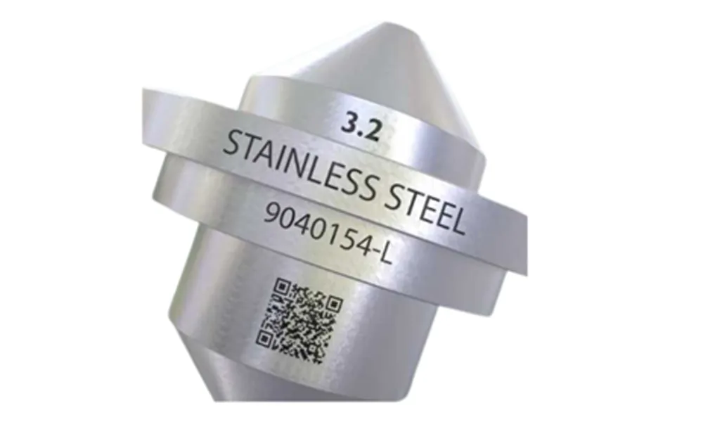
When the specification calls for a recessed engraving, measure the material removed and inspect the affected edges and surrounding finish. Multiple passes may achieve greater depth but also consume time and change the surface. For corrosion-sensitive or cosmetically critical metal parts, the preferred process may instead be the one that produces sufficient readable contrast with less unwanted alteration, even if it is not the usual first choice. Reflective metals such as copper and some aluminum finishes deserve source- and surface-specific trials rather than a categorical “fiber works” or “UV works” verdict.
Plastics: Chemistry, Color and Laser-Sensitive Additives Change the Choice
A drawing that specifies only “ABS” or “PC” is often insufficient to predict the marking result. The exact resin grade, pigment package, reinforcement and laser-marking additives can change absorption and the type of contrast formed. On one formulation, a near-infrared fiber process may yield a stable mark; on another with the same polymer abbreviation, it may yield almost no contrast or visibly melt the surface. UV may provide a better processing window for certain sensitive polymers, but it too can discolor, roughen or deform an unsuitable formulation.
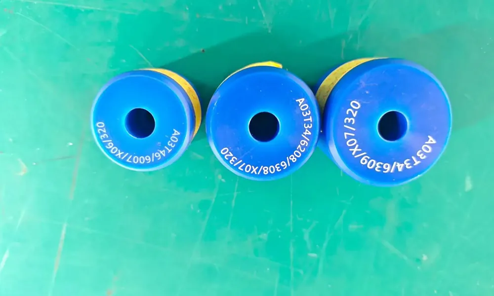
Decide what the mark must survive. A small Data Matrix on an electrical connector must remain readable after the specified handling or environmental exposure, while the connector’s geometry and insulation function must remain within tolerance. A mark that looks clean under a camera but leaves a raised, brittle or weakened surface is not necessarily acceptable. For polypropylene, polyethylene or films, thickness, support during processing and additive content are particularly important; do not approve a source from the polymer family name alone.
Anodized, Painted and Multilayer Parts: Which Layer Must Change?
On a coated component, the key question is often which layer is supposed to change? One marking task may intentionally remove a paint layer to expose contrast underneath. Another may require a color change while keeping a protective anodized or insulating layer functionally intact. Those two targets can favor different wavelengths and settings on the same base metal.
Specify the coating construction and permitted depth of change before testing. Examine whether the mark breaks through a corrosion barrier, changes electrical insulation, exposes metal or lifts the coating near the edges. A highly legible code can still be a failed process if it removes a layer the product needs. Treat decorative anodizing, plated contacts and electrical coatings as distinct applications rather than one generic “coated metal” category.
Glass and Other Fragile Surfaces: Feasibility Is Not the Same as Damage-Free
UV may be worth investigating for selected glass and brittle-surface marking tasks, but transparency at the chosen wavelength, glass composition, focusing conditions and energy delivery all affect whether a usable mark forms. Fine-looking marks can coexist with roughening or microcracks. A published study of 355 nm nanosecond glass grooving demonstrates that the surrounding damage depends on the process conditions; it is ليس a direct performance claim for routine surface marking.
If fracture risk, optical function or surface integrity matters, inspect representative parts beyond naked-eye contrast. Should neither fiber nor UV meet the agreed limits, the correct decision is to evaluate an alternative marking method, not to force an approval between two unsuitable candidates.
How Do Mark Quality, Engraving Depth and Production Cost Compare?
Once both lasers can create a visible mark, the comparison becomes more demanding. Use the same workpiece specification and final acceptance requirements for both sources, even though their optimum settings may be different. The winner is the process that produces an accepted mark consistently and at a workable overall production cost.
A Visible Mark Is Not Necessarily a Readable or Durable Mark
For human-readable text, examine character definition, contrast under the intended lighting and resistance to the handling the product will encounter. For a Data Matrix or QR code, a successful scan on one handheld reader is only an initial functional observation. Symbol size, cell definition, surface reflectivity and the actual reading setup affect reliability. A code that looks clear in a sample photograph can still fail its specified quality requirement.
When the specification requires graded two-dimensional symbols, ISO/IEC 15415:2024 addresses symbol-quality assessment, while ISO/IEC 29158:2025 provides a methodology adapted to direct part marks. Whether and how those methods apply must come from the customer’s marking specification; neither this comparison nor a supplier’s sample photo establishes a universal pass grade. Test any required abrasion, cleaning, chemical or environmental durability separately.
Fine Detail, Heat Effects and Part Integrity
For very small characters or code cells, inspect actual edge definition and readability at the required feature size rather than relying on a quoted spot size. Optics, focus, pulse overlap, mark design, material response and motion accuracy influence the finished feature. UV may offer a useful process window on sensitive surfaces, but a claim that one wavelength is always “more precise” cannot replace inspection under the intended method.
Part integrity can matter more than the apparent sharpness of the mark. On plastics, look for foaming, softened edges, warpage, pinholes, yellowing, a scorched or discolored halo beyond the specified mark boundary, and unwanted changes in surface texture or feel. On metals, consider raised material, altered oxide or finish, and material removal near critical features. UV is capable of thermal effects too. The question is whether a usable settings window meets both marking and substrate requirements.
Engraving Depth and Material-Removal Trade-offs
Engraving requires measurable material removal; a darker surface mark alone does not satisfy that specification. For conventional metal engraving, a suitably configured fiber process is generally the stronger starting trial. Assess the result by actual recess depth, edge condition and surrounding finish. Greater removal may require repeated passes, a different focus strategy or a longer cycle. TRUMPF’s laser-engraving explanation distinguishes material-removing engraving from marking that changes appearance without the same recess.
Do not infer engraving capability from advertised average power alone. Pulse characteristics, beam delivery, actual absorption, target depth and acceptable finish can change the result. A UV system should not be declared incapable of metal removal in every circumstance; it simply is not the automatic first choice for a conventional deeper metal-engraving requirement.
Throughput and Cost per Accepted Mark
“Which laser is faster?” has no reliable universal answer without the mark and acceptance criteria. Compare the time to deliver the same accepted outcome, not an unmatched fiber sample and UV sample produced at different quality levels. Each process should first be optimized independently within safe material and machine limits. Include positioning, focusing, marking passes, handling, in-line reading or inspection, and any rework in the total cycle.
Artwork geometry and fill density also affect cycle time. A densely filled logo can require more scan paths and different heat management than a simple outline of the same overall size. Compare both processes using the actual production artwork, not just the dimensions of its bounding box.
Production economics also include rejected parts, material loss, necessary fixtures or vision, extraction, cooling where required by the configuration, integration, maintenance and equipment cost. A useful measure is cost per accepted marked part = total attributable production and ownership cost over a defined period ÷ the number of accepted marked parts in that period. State the period and allocation assumptions before comparing figures. Neither wavelength alone proves a fixed speed advantage, purchase-price difference or running-cost ratio.
When Does the Usual Fiber-versus-UV Recommendation Fail?
A sensible first choice should be reconsidered when the actual mark fails an important requirement. The following are engineering failure patterns to watch for, not reports of completed customer trials:
- UV on a thin polymer creates a visible mark but distorts the part. Look for shrinkage, surface bumps, pinholes or melting. Research into 355 nm nanosecond processing of PET film identifies photothermal effects; that experimental processing study does not quantify performance for an ordinary industrial marking job. Check the actual formulation, geometry and settings before treating UV as the safer choice.
- Fiber on a formulated plastic gives a better result than the initial UV trial. Certain pigments or laser-sensitive additives can make a polymer respond well to near-infrared marking. If the resulting code passes durability and damage limits, the material-specific evidence matters more than the rule of thumb.
- A readable mark destroys a functional coating. Contrast created by exposing metal may be unacceptable when an anodized, plated or insulating layer must continue performing its job. Inspect what changed beneath the visible mark.
- UV on glass produces an attractive feature with unacceptable cracking. Readability does not override a cracking limit: inspect the surface and, where required, subsurface integrity before accepting the result.
- Neither source achieves a stable passing result. Reconsider the substrate specification, marking method, prepared marking area or another laser/process family. Two poor trials do not justify selecting the less visibly poor result.
These exceptions are why a first-test route should lead to controlled sample verification, not directly to a machine purchase decision.
How Should You Test Fiber and UV Before Choosing a Machine?
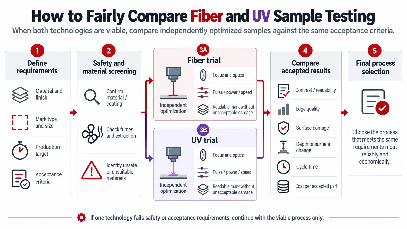
A defensible comparison begins by defining a passing part, not by collecting attractive marking photos. A sample trial should show whether each process has a usable operating window and whether the result can be repeated at the intended production conditions.
Define the Part, Mark and Pass/Fail Criteria Before Testing
Prepare a sample brief that describes the real workpiece and the acceptance conditions. Useful inputs include:
- Material and construction: alloy or resin grade, supplier or formulation when known, pigments/additives, coatings, wall thickness, geometry and starting surface finish.
- Mark definition: artwork or code file, actual content, overall dimensions, minimum feature requirements and intended location on the part.
- Required outcome: contrast, human or machine readability, any specified verification method or code grade, physical depth if required, and permanent or removable surface changes.
- Protection limits: permitted burrs, melting, deformation, cracking, coating removal, color shift or functional changes, including electrical and corrosion-related restrictions.
- ظروف الإنتاج: downstream cleaning or wear exposure, expected volumes, part presentation, acceptable cycle time and how marks will be inspected.
Acceptance limits should be taken from the product specification and its intended use. Do not invent a general-purpose quality threshold just to complete the comparison.
Safety screening comes before process optimization. Confirm the actual polymer, coating and adhesive constituents—particularly possible PVC or other halogen-containing layers—before any trial. Evaluate laser-generated emissions and do not process an unidentified material until its hazards and the required controls have been assessed. OSHA’s laser-hazard guidance emphasizes ventilation for potentially hazardous fumes from laser-material interactions.
Run Fair Trials on Identical Substrates, but Optimize Each Process Separately
Use representative parts from the same material grade, surface treatment and preferably the same production lot. Keep the required artwork, marked area and inspection method the same. The systems do ليس need identical wattage, frequency or scan speed: a fair test allows each source to be tuned for the same required result.
Confirm that the usable marking field covers the complete artwork at the required focus and positioning tolerance. Flexible, curved or inconsistently presented parts may need fixtures or controlled support; include fixture loading, repositioning and refocusing time in the measured production cycle.
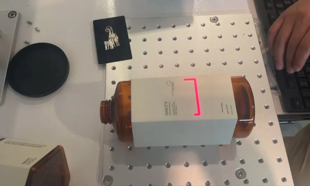
- Record the source and optics configuration and the starting condition of each sample.
- Adjust the relevant pulse, power, focus, scanning, hatch and pass settings within the equipment’s safe operating limits to identify a viable process window.
- Mark more than one representative sample and document settings, observations, rejects and any damage or code-quality failures.
- Inspect under the intended lighting or code-verification method; add magnified, surface, dimensional or functional checks wherever part integrity requires them.
Include handling or environmental tests if the specification demands durability. A single perfect-looking sample at one setting is weaker evidence than a process that passes repeatedly with reasonable tolerance for normal part variation.
Select the Route That Passes in Production, Not Just on a Demo Sample
If only one system meets all acceptance criteria, that is the stronger basis for the selection. If both pass, compare their repeatability, stable settings range, accepted-part cycle time, rejects, fixtures, integration needs and cost per accepted part. If neither passes, stop and reconsider the marking requirement or process rather than treating the comparison as a forced two-option purchase.
Once a viable process direction is established, compare آلات الوسم بليزر الألياف و آلات الوسم بالليزر فوق البنفسجي UV by marking field, workpiece handling, safety configuration and integration needs. These product categories can narrow the machine format, but they do not replace testing on actual parts.
For a preliminary machine-configuration discussion with Zhuorui Laser, provide the actual part or drawing, material grade and surface finish, mark artwork, acceptance criteria and expected production rate. Those details make the discussion specific enough to identify a suitable trial direction; final suitability still depends on testing and approval against your requirements.