Vergleich der Laserquellen
Faser- vs. UV-Laserbeschriftung: Was sollten Sie für Ihr Material wählen?
Faserlaser ist normalerweise der erste Laser, der für routinemäßige Metallcodierungen oder Tiefengravuren getestet wird. UV verdient oft den ersten Test für feine Markierungen auf ausgewählten hitzeempfindlichen Kunststoffen oder empfindlichen Beschichtungen. Das tatsächliche Bauteil, die Markierungsqualität und die Produktionsanforderungen entscheiden über das Ergebnis.
Keine der beiden Quellen ist universell besser. Wählen Sie nicht allein nach dem Materialnamen: Überprüfen Sie die spezifizierte Markierung, den Oberflächenzustand und die Abnahmekriterien an repräsentativen Mustern.
Faser oder UV: Welchen Laser sollten Sie zuerst testen?
Beginnen Sie mit dem Material im Anlieferungszustand, der Veränderung, die Sie an seiner Oberfläche vornehmen müssen, und dem Ausmaß der Veränderung, die das Teil tolerieren kann:
- Blanker Stahl oder Edelstahl, Seriennummern und typische Industrie-Codes: Testen Sie zuerst die Faser, und überprüfen Sie dann Kontrast, Codequalität und Oberflächenanforderungen.
- Metallgravur mit einer festgelegten physischen Tiefe: ist der Faserlaser in der Regel der praktischere erste Versuch, vorausgesetzt, die entstehende Vertiefung und die umgebende Oberfläche sind akzeptabel.
- Wärmeempfindliche Formkunststoffe oder sehr feine Markierungen auf empfindlichen Oberflächen: UV frühzeitig testen, jedoch auf Schmelzen, Farbveränderung, Verformung oder andere inakzeptable Veränderungen achten.
- Pigmentierte Polymere, eloxierte oder lackierte Teile, Glas und komplexe Oberflächenschichten: Untersuchen Sie, welche Schicht die Energie absorbiert und was intakt bleiben muss; ein direkter Vergleichsversuch oder ein anderes Verfahren kann erforderlich sein.
Dabei handelt es sich um erste Versuche, nicht um Schlussfolgerungen darüber, welche Maschine Ihre Abnahmeanforderungen bei der erforderlichen Produktionsrate erfüllen wird. Um die anfänglichen Auswahlmöglichkeiten zu verstehen, betrachten Sie, wie die tatsächliche Oberfläche auf jeden Laser und seine Einstellungen reagiert.
Warum erzeugen Faser- und UV-Laser unterschiedliche Markierungsergebnisse?
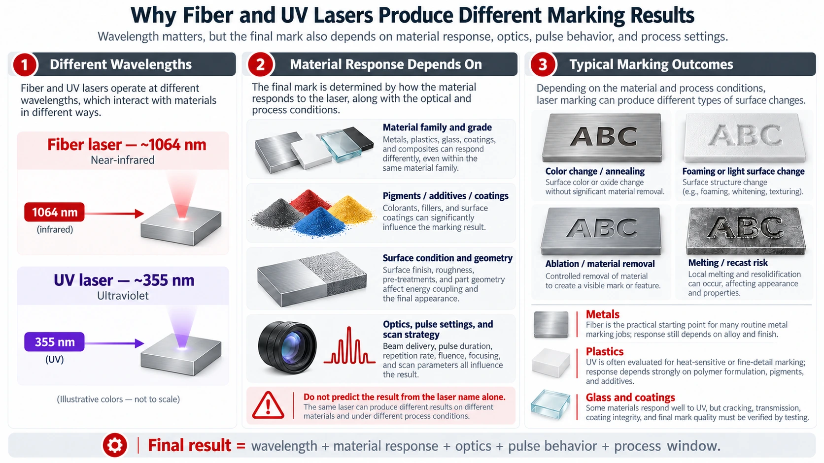
Konventionelle industrielle Faser-Markierungssysteme emittieren üblicherweise Nahinfrarotlicht bei etwa 1,06–1,09 μm, je nach Quellenmodell. Übliche industrielle UV-Markierungssysteme arbeiten bei 355 nm. Die Wellenlänge verändert, wie Energie in das Werkstück einkoppelt, aber die Reaktion des Materials hängt auch von seiner Chemie, Pigmentierung, Füllstoffen, Oxidschicht und Beschichtungen ab. Die Übersicht zur Lasermarkierung von TRUMPF erklärt, warum unterschiedliche Oberflächen und Prozessbedingungen unterschiedliche Markierungsmechanismen erzeugen können.
Das gewünschte Ergebnis kann eine Farb- oder Oxidveränderung, ein Aufschäumen innerhalb eines Polymers, ein Bleichen, ein selektives Entfernen einer Beschichtung oder ein tatsächliches Abtragen von Substratmaterial sein. Dabei handelt es sich um unterschiedliche Fertigungsaufgaben. Ein dunkler Code auf Edelstahl, ein kontrastierendes Zeichen in geformtem Kunststoff und eine vertiefte Gravur erfordern nicht dieselbe Oberflächenreaktion, nur weil alle drei “Lasermarkierung” genannt werden. Harzadditive können ebenfalls die Wellenlänge verändern, auf die ein Kunststoff reagiert, wie beschrieben in TRUMPF-Leitfaden zur Kunststoffmarkierung.
Die Wellenlänge ist nur ein Teil des Prozessfensters. Pulsenergie und -dauer, Wiederholfrequenz, Strahlqualität, Optik, Fokus, Scangeschwindigkeit, Pulsüberlappung, Hatch-Abstand und die Anzahl der Durchläufe beeinflussen, wie viel Energie einen bestimmten Bereich erreicht und wie sich Wärme ansammelt. Kürzere Wellenlängen können unter vergleichbaren optischen Bedingungen kleinere beugungsbegrenzte Spots unterstützen, aber das garantiert weder eine bestimmte Linienbreite noch eine bestimmte Codequalität auf einer realen Maschine. Ebenso wird UV manchmal als “Kaltmarkierung” bezeichnet, weil es in geeigneten Anwendungen unerwünschte Umgebungseffekte reduzieren kann; Die 355-nm-Verarbeitung ist nicht grundsätzlich frei von Wärme. Das tatsächliche Bauteil und die Einstellungen bestimmen, ob das Ergebnis akzeptabel ist.
Welcher Laser ist der bessere Ausgangspunkt für Ihr Material und Ihre Markierung?
Die beste Ausgangsquelle kann sich ändern, selbst wenn das Grundmaterial gleich bleibt. Das Markieren einer Seriennummer auf Edelstahl ist eine andere Aufgabe als das Gravieren einer vorgegebenen Vertiefung, ebenso wie das Entfernen von Farbe von Aluminium sich vom Markieren des blanken Metalls unterscheidet. Diese Tabelle ist eine Leitfaden für Ersttests, kein zertifiziertes Materialverträglichkeitsdiagramm.
| Material oder tatsächliche Oberfläche | Erforderliche Markierung | Sinnvoller erster Test | Was die Auswahl ungültig machen könnte |
|---|---|---|---|
| Unbeschichteter Stahl oder Edelstahl | Lesbare Seriennummer, Logo oder Rückverfolgbarkeitscode | Faser | Unzureichende Codeverifizierung, nicht akzeptable Verfärbung oder Einschränkungen hinsichtlich Oberflächenfinish und Korrosion |
| Stahl und andere geeignete Metalle | Messbare gravierte Vertiefung statt ausschließlich Oberflächenkontrast | Faser | Unzureichende Tiefe, erhabene Kanten, wiederaufgeschmolzenes Material, übermäßige Zykluszeit oder Veränderungen der Bauteilintegrität |
| Kupfer, Aluminium oder empfindliche reflektierende Metalloberflächen | Feine Markierung mit kontrolliertem Kontrast und begrenzter Oberflächenveränderung | Faser- und UV-Laser entsprechend der Oberfläche und Markierung bewerten | Schwache Absorption, instabiler Kontrast, Beschädigung der Oberfläche oder eine nicht akzeptable thermische Reaktion |
| Formteile aus ABS, PC, PA oder verwandten technischen Kunststoffen | Kleiner, kontrastreicher Text oder Code ohne inakzeptable Oberflächenschäden | UV für hitzeempfindliche Typen; Faser kann für laserresponsive Formulierungen geeignet sein | Harzadditive, Pigment, Schaumbildung, Schmelzen, Vergilben oder Haltbarkeitsversagen |
| PP, PE, transparente oder dünne Polymerfolien | Lesbare Markierung ohne Verzug, Perforation oder Verlust der Folienfunktion | UV zuerst erwägen, wo angebracht; Faser testen, wenn die Formulierung es unterstützt | Schlechte Absorption, Nadellöcher, Schrumpfung, Wärmeverformung oder geringer Kontrast |
| Eloxiertes Aluminium, lackiertes Metall, galvanisch beschichtete Teile oder beschichtete Polymere | Kontrollierte Farbänderung oder selektive Schichtentfernung | Je nach Zielschicht auswählen; bei Unsicherheit beide testen | Angriff auf das Grundmaterial, freigelegte leitfähige Schicht, Verlust des Korrosionsschutzes oder Ablösung der Beschichtung |
| Glas oder eine andere spröde transparente Oberfläche | Feines Merkmal mit einer definierten Grenze für Oberflächenschäden | UV ist ein Kandidat mit bedingter Machbarkeit | Unzureichende Absorption, Risse, Rauheit oder Schäden unter der sichtbaren Oberfläche; möglicherweise ist ein anderes Verfahren erforderlich |
Uncoated Metals: Readable Identification Versus Deep Engraving
For a steel bracket, stainless instrument or metal nameplate, a pulsed fiber laser is commonly worth testing for identification. Depending on the requirement, it can be evaluated for contrast-producing surface changes or controlled material removal. A dark Data Matrix still needs code verification, and visible contrast does not establish engraving depth. Legibility, geometry, permanence and surface condition require separate acceptance checks.
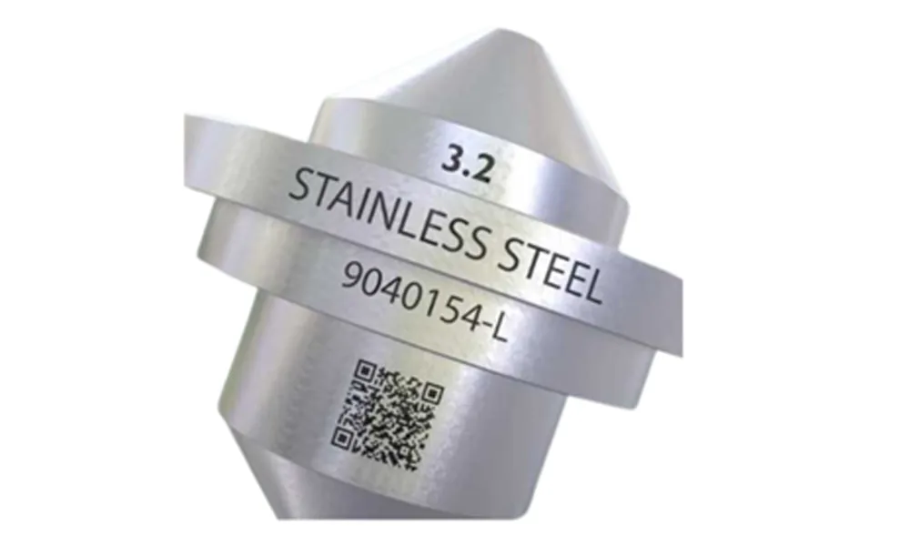
When the specification calls for a recessed engraving, measure the material removed and inspect the affected edges and surrounding finish. Multiple passes may achieve greater depth but also consume time and change the surface. For corrosion-sensitive or cosmetically critical metal parts, the preferred process may instead be the one that produces sufficient readable contrast with less unwanted alteration, even if it is not the usual first choice. Reflective metals such as copper and some aluminum finishes deserve source- and surface-specific trials rather than a categorical “fiber works” or “UV works” verdict.
Plastics: Chemistry, Color and Laser-Sensitive Additives Change the Choice
A drawing that specifies only “ABS” or “PC” is often insufficient to predict the marking result. The exact resin grade, pigment package, reinforcement and laser-marking additives can change absorption and the type of contrast formed. On one formulation, a near-infrared fiber process may yield a stable mark; on another with the same polymer abbreviation, it may yield almost no contrast or visibly melt the surface. UV may provide a better processing window for certain sensitive polymers, but it too can discolor, roughen or deform an unsuitable formulation.
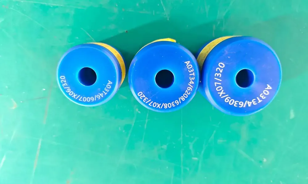
Decide what the mark must survive. A small Data Matrix on an electrical connector must remain readable after the specified handling or environmental exposure, while the connector’s geometry and insulation function must remain within tolerance. A mark that looks clean under a camera but leaves a raised, brittle or weakened surface is not necessarily acceptable. For polypropylene, polyethylene or films, thickness, support during processing and additive content are particularly important; do not approve a source from the polymer family name alone.
Anodized, Painted and Multilayer Parts: Which Layer Must Change?
On a coated component, the key question is often which layer is supposed to change? One marking task may intentionally remove a paint layer to expose contrast underneath. Another may require a color change while keeping a protective anodized or insulating layer functionally intact. Those two targets can favor different wavelengths and settings on the same base metal.
Specify the coating construction and permitted depth of change before testing. Examine whether the mark breaks through a corrosion barrier, changes electrical insulation, exposes metal or lifts the coating near the edges. A highly legible code can still be a failed process if it removes a layer the product needs. Treat decorative anodizing, plated contacts and electrical coatings as distinct applications rather than one generic “coated metal” category.
Glass and Other Fragile Surfaces: Feasibility Is Not the Same as Damage-Free
UV may be worth investigating for selected glass and brittle-surface marking tasks, but transparency at the chosen wavelength, glass composition, focusing conditions and energy delivery all affect whether a usable mark forms. Fine-looking marks can coexist with roughening or microcracks. A published study of 355 nm nanosecond glass grooving demonstrates that the surrounding damage depends on the process conditions; it is nicht a direct performance claim for routine surface marking.
If fracture risk, optical function or surface integrity matters, inspect representative parts beyond naked-eye contrast. Should neither fiber nor UV meet the agreed limits, the correct decision is to evaluate an alternative marking method, not to force an approval between two unsuitable candidates.
How Do Mark Quality, Engraving Depth and Production Cost Compare?
Once both lasers can create a visible mark, the comparison becomes more demanding. Use the same workpiece specification and final acceptance requirements for both sources, even though their optimum settings may be different. The winner is the process that produces an accepted mark consistently and at a workable overall production cost.
A Visible Mark Is Not Necessarily a Readable or Durable Mark
For human-readable text, examine character definition, contrast under the intended lighting and resistance to the handling the product will encounter. For a Data Matrix or QR code, a successful scan on one handheld reader is only an initial functional observation. Symbol size, cell definition, surface reflectivity and the actual reading setup affect reliability. A code that looks clear in a sample photograph can still fail its specified quality requirement.
When the specification requires graded two-dimensional symbols, ISO/IEC 15415:2024 addresses symbol-quality assessment, while ISO/IEC 29158:2025 provides a methodology adapted to direct part marks. Whether and how those methods apply must come from the customer’s marking specification; neither this comparison nor a supplier’s sample photo establishes a universal pass grade. Test any required abrasion, cleaning, chemical or environmental durability separately.
Fine Detail, Heat Effects and Part Integrity
For very small characters or code cells, inspect actual edge definition and readability at the required feature size rather than relying on a quoted spot size. Optics, focus, pulse overlap, mark design, material response and motion accuracy influence the finished feature. UV may offer a useful process window on sensitive surfaces, but a claim that one wavelength is always “more precise” cannot replace inspection under the intended method.
Part integrity can matter more than the apparent sharpness of the mark. On plastics, look for foaming, softened edges, warpage, pinholes, yellowing, a scorched or discolored halo beyond the specified mark boundary, and unwanted changes in surface texture or feel. On metals, consider raised material, altered oxide or finish, and material removal near critical features. UV is capable of thermal effects too. The question is whether a usable settings window meets both marking and substrate requirements.
Engraving Depth and Material-Removal Trade-offs
Engraving requires measurable material removal; a darker surface mark alone does not satisfy that specification. For conventional metal engraving, a suitably configured fiber process is generally the stronger starting trial. Assess the result by actual recess depth, edge condition and surrounding finish. Greater removal may require repeated passes, a different focus strategy or a longer cycle. TRUMPF’s laser-engraving explanation distinguishes material-removing engraving from marking that changes appearance without the same recess.
Do not infer engraving capability from advertised average power alone. Pulse characteristics, beam delivery, actual absorption, target depth and acceptable finish can change the result. A UV system should not be declared incapable of metal removal in every circumstance; it simply is not the automatic first choice for a conventional deeper metal-engraving requirement.
Throughput and Cost per Accepted Mark
“Which laser is faster?” has no reliable universal answer without the mark and acceptance criteria. Compare the time to deliver the same accepted outcome, not an unmatched fiber sample and UV sample produced at different quality levels. Each process should first be optimized independently within safe material and machine limits. Include positioning, focusing, marking passes, handling, in-line reading or inspection, and any rework in the total cycle.
Artwork geometry and fill density also affect cycle time. A densely filled logo can require more scan paths and different heat management than a simple outline of the same overall size. Compare both processes using the actual production artwork, not just the dimensions of its bounding box.
Production economics also include rejected parts, material loss, necessary fixtures or vision, extraction, cooling where required by the configuration, integration, maintenance and equipment cost. A useful measure is cost per accepted marked part = total attributable production and ownership cost over a defined period ÷ the number of accepted marked parts in that period. State the period and allocation assumptions before comparing figures. Neither wavelength alone proves a fixed speed advantage, purchase-price difference or running-cost ratio.
When Does the Usual Fiber-versus-UV Recommendation Fail?
A sensible first choice should be reconsidered when the actual mark fails an important requirement. The following are engineering failure patterns to watch for, not reports of completed customer trials:
- UV on a thin polymer creates a visible mark but distorts the part. Look for shrinkage, surface bumps, pinholes or melting. Research into 355 nm nanosecond processing of PET film identifies photothermal effects; that experimental processing study does not quantify performance for an ordinary industrial marking job. Check the actual formulation, geometry and settings before treating UV as the safer choice.
- Fiber on a formulated plastic gives a better result than the initial UV trial. Certain pigments or laser-sensitive additives can make a polymer respond well to near-infrared marking. If the resulting code passes durability and damage limits, the material-specific evidence matters more than the rule of thumb.
- A readable mark destroys a functional coating. Contrast created by exposing metal may be unacceptable when an anodized, plated or insulating layer must continue performing its job. Inspect what changed beneath the visible mark.
- UV on glass produces an attractive feature with unacceptable cracking. Readability does not override a cracking limit: inspect the surface and, where required, subsurface integrity before accepting the result.
- Neither source achieves a stable passing result. Reconsider the substrate specification, marking method, prepared marking area or another laser/process family. Two poor trials do not justify selecting the less visibly poor result.
These exceptions are why a first-test route should lead to controlled sample verification, not directly to a machine purchase decision.
How Should You Test Fiber and UV Before Choosing a Machine?
A defensible comparison begins by defining a passing part, not by collecting attractive marking photos. A sample trial should show whether each process has a usable operating window and whether the result can be repeated at the intended production conditions.
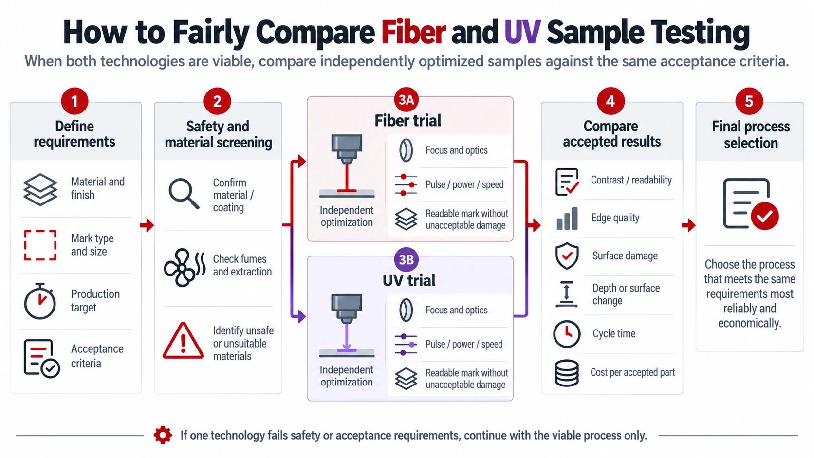
Define the Part, Mark and Pass/Fail Criteria Before Testing
Prepare a sample brief that describes the real workpiece and the acceptance conditions. Useful inputs include:
- Material and construction: alloy or resin grade, supplier or formulation when known, pigments/additives, coatings, wall thickness, geometry and starting surface finish.
- Mark definition: artwork or code file, actual content, overall dimensions, minimum feature requirements and intended location on the part.
- Required outcome: contrast, human or machine readability, any specified verification method or code grade, physical depth if required, and permanent or removable surface changes.
- Protection limits: permitted burrs, melting, deformation, cracking, coating removal, color shift or functional changes, including electrical and corrosion-related restrictions.
- Produktionsbedingungen: downstream cleaning or wear exposure, expected volumes, part presentation, acceptable cycle time and how marks will be inspected.
Acceptance limits should be taken from the product specification and its intended use. Do not invent a general-purpose quality threshold just to complete the comparison.
Safety screening comes before process optimization. Confirm the actual polymer, coating and adhesive constituents—particularly possible PVC or other halogen-containing layers—before any trial. Evaluate laser-generated emissions and do not process an unidentified material until its hazards and the required controls have been assessed. OSHA’s laser-hazard guidance emphasizes ventilation for potentially hazardous fumes from laser-material interactions.
Run Fair Trials on Identical Substrates, but Optimize Each Process Separately
Use representative parts from the same material grade, surface treatment and preferably the same production lot. Keep the required artwork, marked area and inspection method the same. The systems do nicht need identical wattage, frequency or scan speed: a fair test allows each source to be tuned for the same required result.
Confirm that the usable marking field covers the complete artwork at the required focus and positioning tolerance. Flexible, curved or inconsistently presented parts may need fixtures or controlled support; include fixture loading, repositioning and refocusing time in the measured production cycle.
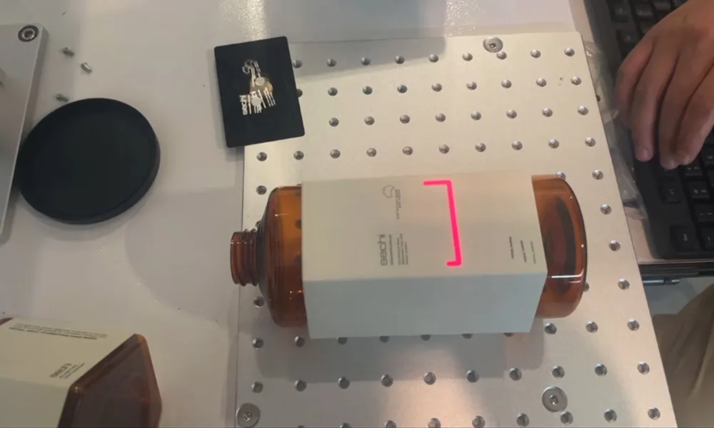
- Record the source and optics configuration and the starting condition of each sample.
- Adjust the relevant pulse, power, focus, scanning, hatch and pass settings within the equipment’s safe operating limits to identify a viable process window.
- Mark more than one representative sample and document settings, observations, rejects and any damage or code-quality failures.
- Inspect under the intended lighting or code-verification method; add magnified, surface, dimensional or functional checks wherever part integrity requires them.
Include handling or environmental tests if the specification demands durability. A single perfect-looking sample at one setting is weaker evidence than a process that passes repeatedly with reasonable tolerance for normal part variation.
Select the Route That Passes in Production, Not Just on a Demo Sample
If only one system meets all acceptance criteria, that is the stronger basis for the selection. If both pass, compare their repeatability, stable settings range, accepted-part cycle time, rejects, fixtures, integration needs and cost per accepted part. If neither passes, stop and reconsider the marking requirement or process rather than treating the comparison as a forced two-option purchase.
Once a viable process direction is established, compare Faserlaser-Beschriftungsmaschine und UV-Laser-Beschriftungsmaschinen by marking field, workpiece handling, safety configuration and integration needs. These product categories can narrow the machine format, but they do not replace testing on actual parts.
For a preliminary machine-configuration discussion with Zhuorui Laser, provide the actual part or drawing, material grade and surface finish, mark artwork, acceptance criteria and expected production rate. Those details make the discussion specific enough to identify a suitable trial direction; final suitability still depends on testing and approval against your requirements.