Сравнение лазерных источников
Волоконный или УФ-лазер для маркировки: что выбрать для вашего материала?
Волоконный лазер обычно первым тестируют для стандартных маркировочных кодов на металле или углубленной гравировки. УФ-лазер часто заслуживает первой пробной проверки для тонкой маркировки на отдельных термочувствительных пластиках или деликатных покрытиях. Фактическая деталь, качество маркировки и требования производства определяют результат.
Ни один источник не является универсально лучшим. Не выбирайте только по названию материала: проверьте заданную маркировку, состояние поверхности и критерии приемки на представительных образцах.
Волоконный или УФ: какой лазер следует проверить первым?
Начните с материала в исходном виде, изменения, которое нужно внести в его поверхность, и величины изменения, которую деталь может выдержать:
- Незащищённая сталь или нержавеющая сталь, серийные номера и типичные промышленные коды: сначала протестируйте волоконный лазер, затем проверьте контраст, качество кода и требования к отделке.
- Гравировка по металлу с заданной физической глубиной: волоконный лазер обычно является более практичным вариантом для начального испытания, при условии, что полученное углубление и окружающая поверхность приемлемы.
- Термочувствительные формованные пластики или очень тонкие отметки на деликатных поверхностях: проведите УФ-тест на раннем этапе, но проверьте на плавление, изменение цвета, деформацию или другие неприемлемые изменения.
- Пигментированные полимеры, анодированные или окрашенные детали, стекло и сложные поверхностные слои: выясните, какой слой поглощает энергию и что должно остаться неповреждённым; может потребоваться сравнительное испытание или другой процесс.
Это начальные испытания, а не выводы о том, какая машина будет соответствовать вашим требованиям приёмки при необходимой производительности. Чтобы понять первоначальный выбор, посмотрите, как фактическая поверхность реагирует на каждый лазер и его настройки.
Почему волоконные и УФ-лазеры дают разные результаты маркировки?
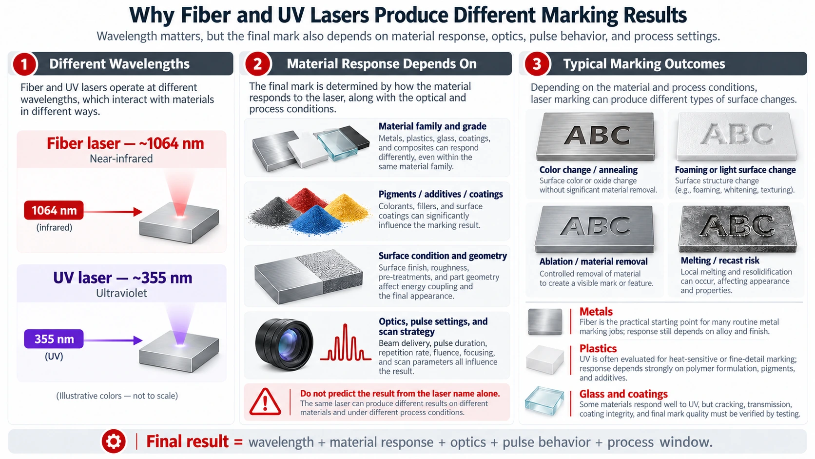
Обычные промышленные волоконные системы маркировки обычно излучают ближний инфракрасный свет в диапазоне около 1,06–1,09 мкм в зависимости от модели источника. Обычные промышленные УФ-системы маркировки работают на длине волны 355 нм. Длина волны меняет то, как энергия вводится в заготовку, но реакция материала также зависит от его химического состава, пигментации, наполнителей, оксидного слоя и покрытий. В обзоре лазерной маркировки от TRUMPF объясняется, почему разные поверхности и условия обработки могут приводить к разным механизмам маркировки.
Желаемый результат может представлять собой изменение цвета или оксидного слоя, вспенивание внутри полимера, отбеливание, избирательное удаление покрытия или фактическое удаление материала подложки. Это разные производственные задачи. Темный код на нержавеющей стали, контрастный символ в формованном пластике и углубленная гравировка не требуют одинаковой реакции поверхности только потому, что все три называются “лазерной маркировкой”. Добавки в смолу также могут изменять длину волны, на которую реагирует пластик, как описано в Рекомендации TRUMPF по маркировке пластика.
Длина волны — лишь часть технологического окна. Энергия и длительность импульса, частота повторения, качество пучка, оптика, фокусировка, скорость сканирования, перекрытие импульсов, шаг штриховки и число проходов влияют на то, сколько энергии достигает заданной области и как накапливается тепло. Более короткие длины волн могут обеспечивать меньшие пятна, ограниченные дифракцией, при сопоставимых оптических условиях, но это не гарантирует конкретную ширину линии или качество кода на реальной машине. Кроме того, УФ иногда называют “холодной маркировкой”, поскольку в подходящих применениях он может уменьшать нежелательные побочные эффекты вокруг зоны обработки; Обработка излучением с длиной волны 355 нм сама по себе не свободна от нагрева. Конкретная деталь и настройки определяют, приемлем ли результат.
Какой лазер является лучшей отправной точкой для вашего материала и маркировки?
Оптимальный исходный источник может меняться, даже если базовый материал не меняется. Нанесение серийного номера на нержавеющую сталь — это другая задача, чем гравировка заданного углубления, точно так же как удаление краски с алюминия отличается от маркировки чистого металла. Эта таблица представляет собой руководство по предварительному тестированию, а не сертифицированная таблица совместимости материалов.
| Материал или фактическая поверхность | Требуемая маркировка | Целесообразный первый тест | Что может сделать выбор недействительным |
|---|---|---|---|
| Сталь без покрытия или нержавеющая сталь | Читаемый серийный номер, логотип или код прослеживаемости | Волоконный | Недостаточная проверка кода, недопустимое обесцвечивание или ограничения по отделке поверхности и коррозии |
| Сталь и другие подходящие металлы | Измеримое гравированное углубление, а не только поверхностный контраст | Волоконный | Недостаточная глубина, приподнятые края, переплавленный материал, чрезмерное время цикла или изменения целостности детали |
| Медь, алюминий или чувствительные отражающие металлические покрытия | Тонкая метка с контролируемым контрастом и ограниченным изменением поверхности | Оценивайте волоконный и УФ-лазер в зависимости от отделки и метки | Слабое поглощение, нестабильный контраст, повреждение покрытия или недопустимая термическая реакция |
| Формованные ABS, PC, PA или родственные конструкционные пластики | Мелкий высококонтрастный текст или код без недопустимого повреждения поверхности | УФ-лазер для термочувствительных марок; волоконный лазер может подойти для лазерно-чувствительных составов | Добавки в смолу, пигмент, вспенивание, плавление, пожелтение или отказ по долговечности |
| PP, PE, прозрачные или тонкие полимерные пленки | Читаемая маркировка без коробления, перфорации или потери функции пленки | Сначала рассматривайте УФ, где это уместно; проверяйте волоконный лазер, если состав это позволяет | Плохое поглощение, точечные отверстия, усадка, термическая деформация или низкий контраст |
| Анодированный алюминий, окрашенный металл, детали с гальваническим покрытием или полимеры с покрытием | Контролируемое изменение цвета или избирательное удаление слоя | Выбирайте в зависимости от целевого слоя; при неопределенности проверяйте оба варианта | Повреждение основного материала, обнажение проводящего слоя, потеря антикоррозионной защиты или отслоение покрытия |
| Стекло или другая хрупкая прозрачная поверхность | Мелкий элемент с заданным ограничением повреждения поверхности | УФ-излучение — условно приемлемый вариант | Недостаточное поглощение, трещины, шероховатость или повреждение под видимой поверхностью; может потребоваться другой процесс |
Uncoated Metals: Readable Identification Versus Deep Engraving
For a steel bracket, stainless instrument or metal nameplate, a pulsed fiber laser is commonly worth testing for identification. Depending on the requirement, it can be evaluated for contrast-producing surface changes or controlled material removal. A dark Data Matrix still needs code verification, and visible contrast does not establish engraving depth. Legibility, geometry, permanence and surface condition require separate acceptance checks.
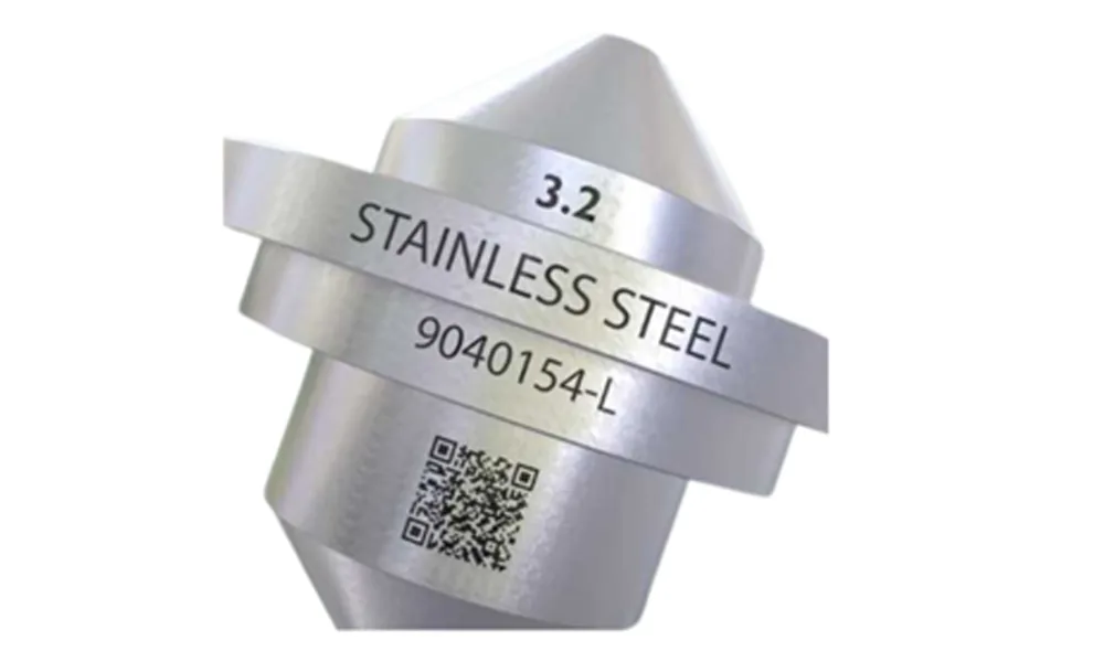
When the specification calls for a recessed engraving, measure the material removed and inspect the affected edges and surrounding finish. Multiple passes may achieve greater depth but also consume time and change the surface. For corrosion-sensitive or cosmetically critical metal parts, the preferred process may instead be the one that produces sufficient readable contrast with less unwanted alteration, even if it is not the usual first choice. Reflective metals such as copper and some aluminum finishes deserve source- and surface-specific trials rather than a categorical “fiber works” or “UV works” verdict.
Plastics: Chemistry, Color and Laser-Sensitive Additives Change the Choice
A drawing that specifies only “ABS” or “PC” is often insufficient to predict the marking result. The exact resin grade, pigment package, reinforcement and laser-marking additives can change absorption and the type of contrast formed. On one formulation, a near-infrared fiber process may yield a stable mark; on another with the same polymer abbreviation, it may yield almost no contrast or visibly melt the surface. UV may provide a better processing window for certain sensitive polymers, but it too can discolor, roughen or deform an unsuitable formulation.
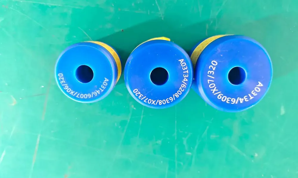
Decide what the mark must survive. A small Data Matrix on an electrical connector must remain readable after the specified handling or environmental exposure, while the connector’s geometry and insulation function must remain within tolerance. A mark that looks clean under a camera but leaves a raised, brittle or weakened surface is not necessarily acceptable. For polypropylene, polyethylene or films, thickness, support during processing and additive content are particularly important; do not approve a source from the polymer family name alone.
Anodized, Painted and Multilayer Parts: Which Layer Must Change?
On a coated component, the key question is often which layer is supposed to change? One marking task may intentionally remove a paint layer to expose contrast underneath. Another may require a color change while keeping a protective anodized or insulating layer functionally intact. Those two targets can favor different wavelengths and settings on the same base metal.
Specify the coating construction and permitted depth of change before testing. Examine whether the mark breaks through a corrosion barrier, changes electrical insulation, exposes metal or lifts the coating near the edges. A highly legible code can still be a failed process if it removes a layer the product needs. Treat decorative anodizing, plated contacts and electrical coatings as distinct applications rather than one generic “coated metal” category.
Glass and Other Fragile Surfaces: Feasibility Is Not the Same as Damage-Free
UV may be worth investigating for selected glass and brittle-surface marking tasks, but transparency at the chosen wavelength, glass composition, focusing conditions and energy delivery all affect whether a usable mark forms. Fine-looking marks can coexist with roughening or microcracks. A published study of 355 nm nanosecond glass grooving demonstrates that the surrounding damage depends on the process conditions; it is не a direct performance claim for routine surface marking.
If fracture risk, optical function or surface integrity matters, inspect representative parts beyond naked-eye contrast. Should neither fiber nor UV meet the agreed limits, the correct decision is to evaluate an alternative marking method, not to force an approval between two unsuitable candidates.
How Do Mark Quality, Engraving Depth and Production Cost Compare?
Once both lasers can create a visible mark, the comparison becomes more demanding. Use the same workpiece specification and final acceptance requirements for both sources, even though their optimum settings may be different. The winner is the process that produces an accepted mark consistently and at a workable overall production cost.
A Visible Mark Is Not Necessarily a Readable or Durable Mark
For human-readable text, examine character definition, contrast under the intended lighting and resistance to the handling the product will encounter. For a Data Matrix or QR code, a successful scan on one handheld reader is only an initial functional observation. Symbol size, cell definition, surface reflectivity and the actual reading setup affect reliability. A code that looks clear in a sample photograph can still fail its specified quality requirement.
When the specification requires graded two-dimensional symbols, ISO/IEC 15415:2024 addresses symbol-quality assessment, while ISO/IEC 29158:2025 provides a methodology adapted to direct part marks. Whether and how those methods apply must come from the customer’s marking specification; neither this comparison nor a supplier’s sample photo establishes a universal pass grade. Test any required abrasion, cleaning, chemical or environmental durability separately.
Fine Detail, Heat Effects and Part Integrity
For very small characters or code cells, inspect actual edge definition and readability at the required feature size rather than relying on a quoted spot size. Optics, focus, pulse overlap, mark design, material response and motion accuracy influence the finished feature. UV may offer a useful process window on sensitive surfaces, but a claim that one wavelength is always “more precise” cannot replace inspection under the intended method.
Part integrity can matter more than the apparent sharpness of the mark. On plastics, look for foaming, softened edges, warpage, pinholes, yellowing, a scorched or discolored halo beyond the specified mark boundary, and unwanted changes in surface texture or feel. On metals, consider raised material, altered oxide or finish, and material removal near critical features. UV is capable of thermal effects too. The question is whether a usable settings window meets both marking and substrate requirements.
Engraving Depth and Material-Removal Trade-offs
Engraving requires measurable material removal; a darker surface mark alone does not satisfy that specification. For conventional metal engraving, a suitably configured fiber process is generally the stronger starting trial. Assess the result by actual recess depth, edge condition and surrounding finish. Greater removal may require repeated passes, a different focus strategy or a longer cycle. TRUMPF’s laser-engraving explanation distinguishes material-removing engraving from marking that changes appearance without the same recess.
Do not infer engraving capability from advertised average power alone. Pulse characteristics, beam delivery, actual absorption, target depth and acceptable finish can change the result. A UV system should not be declared incapable of metal removal in every circumstance; it simply is not the automatic first choice for a conventional deeper metal-engraving requirement.
Throughput and Cost per Accepted Mark
“Which laser is faster?” has no reliable universal answer without the mark and acceptance criteria. Compare the time to deliver the same accepted outcome, not an unmatched fiber sample and UV sample produced at different quality levels. Each process should first be optimized independently within safe material and machine limits. Include positioning, focusing, marking passes, handling, in-line reading or inspection, and any rework in the total cycle.
Artwork geometry and fill density also affect cycle time. A densely filled logo can require more scan paths and different heat management than a simple outline of the same overall size. Compare both processes using the actual production artwork, not just the dimensions of its bounding box.
Production economics also include rejected parts, material loss, necessary fixtures or vision, extraction, cooling where required by the configuration, integration, maintenance and equipment cost. A useful measure is cost per accepted marked part = total attributable production and ownership cost over a defined period ÷ the number of accepted marked parts in that period. State the period and allocation assumptions before comparing figures. Neither wavelength alone proves a fixed speed advantage, purchase-price difference or running-cost ratio.
When Does the Usual Fiber-versus-UV Recommendation Fail?
A sensible first choice should be reconsidered when the actual mark fails an important requirement. The following are engineering failure patterns to watch for, not reports of completed customer trials:
- UV on a thin polymer creates a visible mark but distorts the part. Look for shrinkage, surface bumps, pinholes or melting. Research into 355 nm nanosecond processing of PET film identifies photothermal effects; that experimental processing study does not quantify performance for an ordinary industrial marking job. Check the actual formulation, geometry and settings before treating UV as the safer choice.
- Fiber on a formulated plastic gives a better result than the initial UV trial. Certain pigments or laser-sensitive additives can make a polymer respond well to near-infrared marking. If the resulting code passes durability and damage limits, the material-specific evidence matters more than the rule of thumb.
- A readable mark destroys a functional coating. Contrast created by exposing metal may be unacceptable when an anodized, plated or insulating layer must continue performing its job. Inspect what changed beneath the visible mark.
- UV on glass produces an attractive feature with unacceptable cracking. Readability does not override a cracking limit: inspect the surface and, where required, subsurface integrity before accepting the result.
- Neither source achieves a stable passing result. Reconsider the substrate specification, marking method, prepared marking area or another laser/process family. Two poor trials do not justify selecting the less visibly poor result.
These exceptions are why a first-test route should lead to controlled sample verification, not directly to a machine purchase decision.
How Should You Test Fiber and UV Before Choosing a Machine?
A defensible comparison begins by defining a passing part, not by collecting attractive marking photos. A sample trial should show whether each process has a usable operating window and whether the result can be repeated at the intended production conditions.
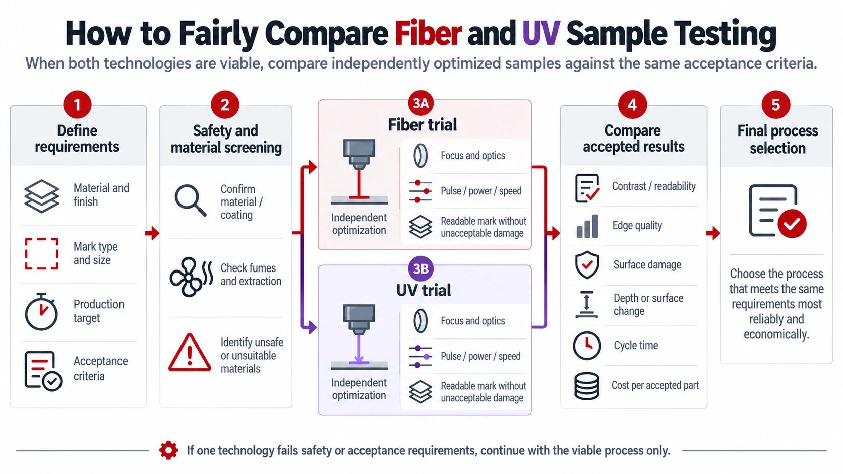
Define the Part, Mark and Pass/Fail Criteria Before Testing
Prepare a sample brief that describes the real workpiece and the acceptance conditions. Useful inputs include:
- Material and construction: alloy or resin grade, supplier or formulation when known, pigments/additives, coatings, wall thickness, geometry and starting surface finish.
- Mark definition: artwork or code file, actual content, overall dimensions, minimum feature requirements and intended location on the part.
- Required outcome: contrast, human or machine readability, any specified verification method or code grade, physical depth if required, and permanent or removable surface changes.
- Protection limits: permitted burrs, melting, deformation, cracking, coating removal, color shift or functional changes, including electrical and corrosion-related restrictions.
- Производственные условия: downstream cleaning or wear exposure, expected volumes, part presentation, acceptable cycle time and how marks will be inspected.
Acceptance limits should be taken from the product specification and its intended use. Do not invent a general-purpose quality threshold just to complete the comparison.
Safety screening comes before process optimization. Confirm the actual polymer, coating and adhesive constituents—particularly possible PVC or other halogen-containing layers—before any trial. Evaluate laser-generated emissions and do not process an unidentified material until its hazards and the required controls have been assessed. OSHA’s laser-hazard guidance emphasizes ventilation for potentially hazardous fumes from laser-material interactions.
Run Fair Trials on Identical Substrates, but Optimize Each Process Separately
Use representative parts from the same material grade, surface treatment and preferably the same production lot. Keep the required artwork, marked area and inspection method the same. The systems do не need identical wattage, frequency or scan speed: a fair test allows each source to be tuned for the same required result.
Confirm that the usable marking field covers the complete artwork at the required focus and positioning tolerance. Flexible, curved or inconsistently presented parts may need fixtures or controlled support; include fixture loading, repositioning and refocusing time in the measured production cycle.
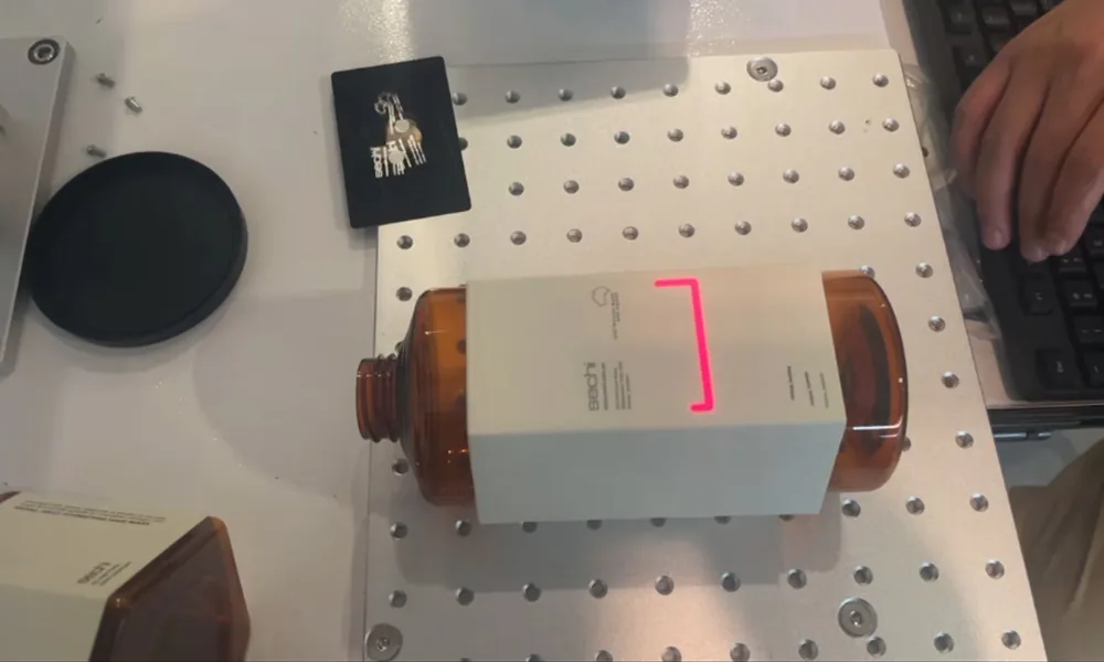
- Record the source and optics configuration and the starting condition of each sample.
- Adjust the relevant pulse, power, focus, scanning, hatch and pass settings within the equipment’s safe operating limits to identify a viable process window.
- Mark more than one representative sample and document settings, observations, rejects and any damage or code-quality failures.
- Inspect under the intended lighting or code-verification method; add magnified, surface, dimensional or functional checks wherever part integrity requires them.
Include handling or environmental tests if the specification demands durability. A single perfect-looking sample at one setting is weaker evidence than a process that passes repeatedly with reasonable tolerance for normal part variation.
Select the Route That Passes in Production, Not Just on a Demo Sample
If only one system meets all acceptance criteria, that is the stronger basis for the selection. If both pass, compare their repeatability, stable settings range, accepted-part cycle time, rejects, fixtures, integration needs and cost per accepted part. If neither passes, stop and reconsider the marking requirement or process rather than treating the comparison as a forced two-option purchase.
Once a viable process direction is established, compare волоконные лазерные маркировочные станки и УФ-лазерные маркировочные машины by marking field, workpiece handling, safety configuration and integration needs. These product categories can narrow the machine format, but they do not replace testing on actual parts.
For a preliminary machine-configuration discussion with Zhuorui Laser, provide the actual part or drawing, material grade and surface finish, mark artwork, acceptance criteria and expected production rate. Those details make the discussion specific enough to identify a suitable trial direction; final suitability still depends on testing and approval against your requirements.