レーザー光源の比較
ファイバー vs UV レーザーマーキング:あなたの材料にはどちらを選ぶべきか?
ファイバーは通常、定型的な金属コードや凹み彫刻をテストする最初のレーザーです。UVは、選択された熱に敏感なプラスチックや繊細なコーティングへの微細マーキングの最初の試行にふさわしいことがよくあります。実際の部品、マーク品質、生産要件が結果を決めます。.
どちらの光源も普遍的に優れているわけではありません。材料名だけで選ばないでください:指定されたマーク、表面状態、合格基準を代表的なサンプルで検証してください。.
ファイバーかUVか:どちらのレーザーを最初にテストすべきですか?
まず、供給されたままの材料、その表面に加える必要がある変化、および部品が許容できる変化量から始めてください:
- 露出した鋼またはステンレス鋼、シリアル番号、一般的な産業コード: まずファイバーをテストし、次にコントラスト、コード品質、仕上げ要件を確認します。.
- 指定された物理的な深さでの金属彫刻: ファイバーは一般に、生じる凹みと周囲の表面が許容できるなら、より実用的な初期トライアルです。.
- 熱に敏感な成形プラスチック、または繊細な表面への非常に微細なマーク: UVを早い段階で試してください。ただし、溶融、色変化、歪み、その他の許容できない変化がないか確認してください。.
- 顔料入りポリマー、陽極酸化処理または塗装された部品、ガラス、および複雑な表面層: どの層がエネルギーを吸収し、何を損なわずに保つ必要があるかを調べてください。並べて比較するトライアルや、別のプロセスが必要になる場合があります。.
これらは 初期トライアル, 、どの機械が必要な生産速度であなたの受入要件を満たすかについての結論ではありません。初期の選択肢を理解するには、実際の表面が各レーザーとその設定にどう反応するかを確認してください。.
ファイバーレーザーとUVレーザーでマーキング結果が異なるのはなぜですか?
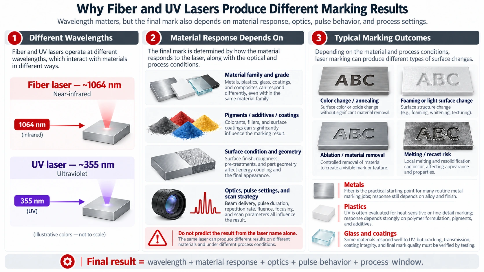
従来の産業用 ファイバーマーキングシステム は、光源モデルに応じて約1.06~1.09 μmの近赤外光を一般的に放射します。一般的な産業用 UVマーキングシステム は355 nmで動作します。波長はエネルギーがワークピースに結合する仕方を変えますが、材料の応答はその化学的性質、顔料、充填剤、酸化層、コーティングにも依存します。 TRUMPFのレーザーマーキング概要 は、異なる表面や処理条件によって異なるマーキングメカニズムが生じる理由を説明しています。.
望ましい結果は、色や酸化物の変化、ポリマー内部の発泡、漂白、コーティングの選択的除去、あるいは基材材料そのものの除去である場合があります。これらは異なる製造作業です。ステンレス鋼上の暗いコード、成形プラスチック内のコントラストのある文字、および凹部への彫刻は、三つとも「レーザーマーキング」と呼ばれているというだけの理由で、同じ表面応答を必要とするわけではありません。樹脂添加剤も、次に説明するように、プラスチックが反応する波長を変える可能性があります TRUMPFのプラスチックマーキングに関するガイダンス.
波長はプロセスウィンドウの一部にすぎません。パルスエネルギーと持続時間、繰り返し周波数、ビーム品質、光学系、焦点、走査速度、パルス重なり、ハッチ間隔、およびパス数は、特定の領域に到達するエネルギー量と熱の蓄積具合に影響します。より短い波長は、同等の光学条件下で、回折限界のより小さいスポットを支えることができますが、それが実機上での特定の線幅やコード品質を保証するわけではありません。同様に、UVは、適切な用途では周囲への不要な影響を低減できるため、「コールドマーキング」と説明されることがあります; 355 nmの加工が本質的に熱を伴わないというわけではありません. 。実際の部品と設定によって、その結果が許容できるかどうかが決まります。.
お使いの材料とマークにとって、どのレーザーがより良い出発点になるか?
最適な出発点となる光源は、基材が変わらなくても変わり得ます。ステンレス鋼にシリアル番号をマーキングするのは、指定された凹部を彫刻するのとは異なる作業です。アルミニウムから塗料を除去するのが、裸の金属にマーキングするのとは異なるのと同じです。この表は 初回試験のスクリーニングガイドであり、認証済みの材料適合性チャートではありません.
| 材料または実際の表面 | 必要なマーク | 妥当な初回試験 | 選択が無効になる可能性のある要因 |
|---|---|---|---|
| 未コーティング鋼またはステンレス鋼 | 読み取り可能なシリアル番号、ロゴ、またはトレーサビリティコード | ファイバー | コード検証が不十分、許容できない変色、または表面仕上げ・耐食性の制約 |
| 鋼およびその他の適切な金属 | 表面コントラストだけではなく、測定可能な彫刻凹部 | ファイバー | 深さ不足、盛り上がった縁、リキャスト材、過剰なサイクルタイム、または部品の完全性変化 |
| 銅、アルミニウム、または影響を受けやすい反射性金属仕上げ | 表面変化を限定した、微細で制御されたコントラストのマーク | 仕上げとマークに応じてファイバーとUVを評価する | 吸収が弱い、コントラストが不安定、仕上げの損傷、または許容できない熱応答 |
| 成形されたABS、PC、PAまたは関連するエンジニアリングプラスチック | 許容できない表面損傷を伴わない、小さく高コントラストな文字またはコード | 熱に敏感なグレードにはUV、レーザー応答性配合にはファイバーが適する場合がある | 樹脂添加剤、顔料、発泡、溶融、黄変または耐久性の低下 |
| PP、PE、透明または薄いポリマーフィルム | 反り、穿孔、またはフィルム機能の損失のない読み取り可能なマーク | 適切な場合はまずUVを検討し、配合が対応する場合はファイバーを試験する | 吸収不良、ピンホール、収縮、熱変形または低コントラスト |
| 陽極酸化アルミニウム、塗装金属、めっき部品、またはコーティングされたポリマー | 制御された色変化または選択的な層除去 | 対象層に応じて選択する。不確かな場合は両方を試験する | 基材への侵食、導電層の露出、防食性の喪失、またはコーティングの剥離 |
| ガラスまたは他の脆性透明表面 | 表面損傷に規定の限界がある微細形状 | UVは条件付きの実現可能性候補である | 吸収不足、亀裂、粗さ、または可視表面下の損傷。別のプロセスが必要になる場合がある |
未コーティング金属:読み取り可能な識別と深い彫刻の比較
鋼製ブラケット、ステンレス製器具、金属製銘板の場合、識別にはパルスファイバーレーザーを試験する価値が一般にあります。要件に応じて、コントラストを生む表面変化または制御された材料除去について評価できます。暗いマークは データマトリックス 依然としてコード検証が必要であり、目に見えるコントラストは彫刻深さを確立するものではありません。可読性、幾何形状、耐久性、表面状態には個別の受入検査が必要です。.
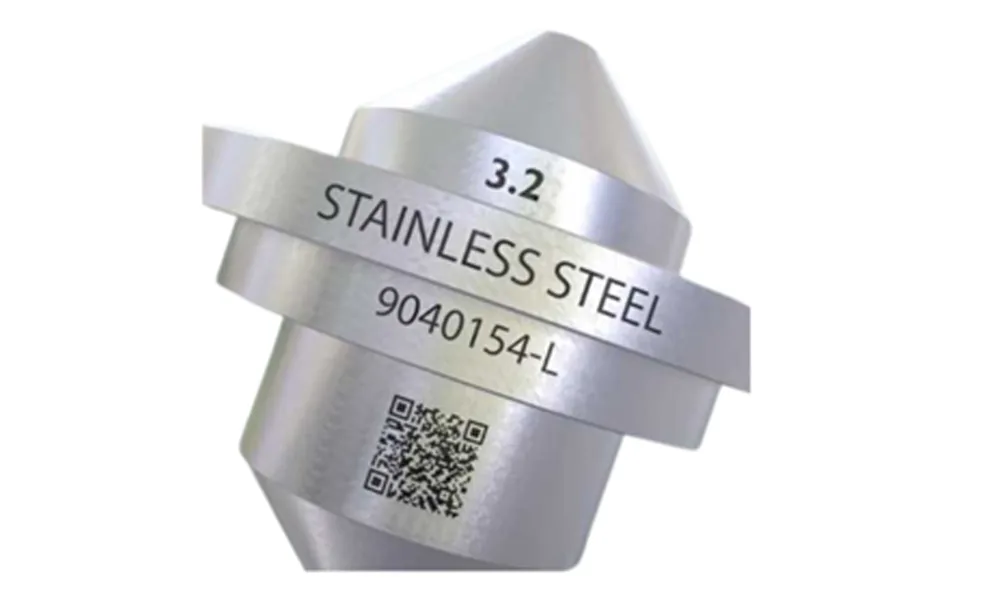
仕様が要求するのが 凹み彫刻, である場合、除去された材料を測定し、影響を受けたエッジと周囲の仕上げを検査します。複数回のパスでより深い彫刻が得られる場合がありますが、時間を消費し、表面を変化させます。腐食に敏感な金属部品や外観上重要な金属部品では、通常の第一選択でなくても、不要な変化を少なく抑えつつ十分な読み取り可能コントラストを生み出すプロセスが好まれる場合があります。銅や一部のアルミニウム仕上げなどの反射性金属は、「ファイバーが使える」「UVが使える」と一律に判断するのではなく、光源と表面に固有の試験を行う価値があります。.
プラスチック:化学組成、色、レーザー感受性添加剤が選択を変える
図面に「ABS」または「PC」とだけ指定されている場合、マーキング結果を予測するには不十分なことがよくあります。正確な樹脂グレード、顔料パッケージ、強化材、レーザーマーキング添加剤によって、吸収や形成されるコントラストの種類が変わり得ます。ある配合では、近赤外ファイバー方式が安定したマークをもたらす一方、同じポリマー略称の別の配合では、ほとんどコントラストが得られない、または表面が目に見えて溶融することがあります。UVは特定の敏感なポリマーにとってより良い加工ウィンドウを提供できる場合がありますが、不適切な配合では変色、粗面化、変形を起こすこともあります。.
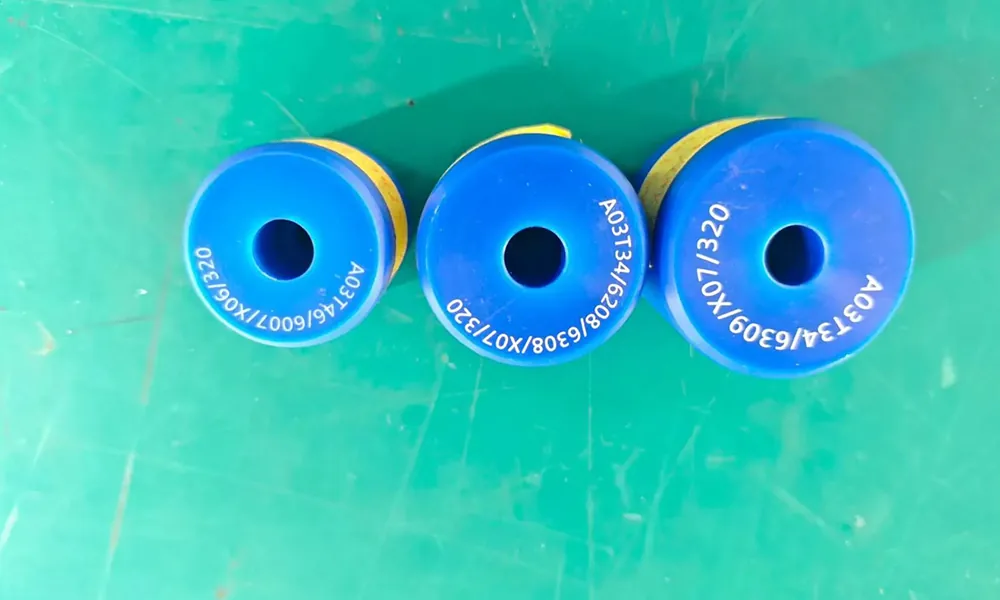
マークが何に耐える必要があるかを決めてください。電気コネクタ上の小さなData Matrixは、指定された取り扱いや環境曝露の後も読み取り可能でなければならず、一方でコネクタの形状と絶縁機能は公差内に保たれる必要があります。カメラ下ではきれいに見えても、盛り上がった、脆い、または弱くなった表面を残すマークは、必ずしも許容できるとは限りません。ポリプロピレン、ポリエチレン、またはフィルムでは、厚さ、加工中の支持、添加剤含有量が特に重要です。ポリマーファミリー名だけで光源を承認しないでください。.
陽極酸化、塗装、多層部品:どの層を変化させる必要があるか?
被覆された部品では、重要な問いはしばしば次のとおりです どの層が変化するべきか? あるマーキング作業では、下のコントラストを露出させるために塗装層を意図的に除去することがあります。別の作業では、保護用の陽極酸化層または絶縁層を機能的に損なわずに色変化を要求することがあります。これら2つの目標は、同じ母材上で異なる波長と設定を有利にすることがあります。.
試験前に、コーティング構成と許容される変化深さを指定してください。マークが防食バリアを貫通するか、電気絶縁を変化させるか、金属を露出させるか、または端部付近でコーティングを持ち上げるかを調べてください。非常に判読しやすいコードであっても、製品が必要とする層を除去している場合は、失敗したプロセスであり得ます。装飾用陽極酸化、めっき接点、電気コーティングは、一般的な「被覆金属」カテゴリではなく、個別の用途として扱ってください。.
Glass and Other Fragile Surfaces: Feasibility Is Not the Same as Damage-Free
UV may be worth investigating for selected glass and brittle-surface marking tasks, but transparency at the chosen wavelength, glass composition, focusing conditions and energy delivery all affect whether a usable mark forms. Fine-looking marks can coexist with roughening or microcracks. A published study of 355 nm nanosecond glass grooving demonstrates that the surrounding damage depends on the process conditions; it is ではない a direct performance claim for routine surface marking.
If fracture risk, optical function or surface integrity matters, inspect representative parts beyond naked-eye contrast. Should neither fiber nor UV meet the agreed limits, the correct decision is to evaluate an alternative marking method, not to force an approval between two unsuitable candidates.
How Do Mark Quality, Engraving Depth and Production Cost Compare?
Once both lasers can create a visible mark, the comparison becomes more demanding. Use the same workpiece specification and final acceptance requirements for both sources, even though their optimum settings may be different. The winner is the process that produces an accepted mark consistently and at a workable overall production cost.
A Visible Mark Is Not Necessarily a Readable or Durable Mark
For human-readable text, examine character definition, contrast under the intended lighting and resistance to the handling the product will encounter. For a Data Matrix or QR code, a successful scan on one handheld reader is only an initial functional observation. Symbol size, cell definition, surface reflectivity and the actual reading setup affect reliability. A code that looks clear in a sample photograph can still fail its specified quality requirement.
When the specification requires graded two-dimensional symbols, ISO/IEC 15415:2024 addresses symbol-quality assessment, while ISO/IEC 29158:2025 provides a methodology adapted to direct part marks. Whether and how those methods apply must come from the customer’s marking specification; neither this comparison nor a supplier’s sample photo establishes a universal pass grade. Test any required abrasion, cleaning, chemical or environmental durability separately.
Fine Detail, Heat Effects and Part Integrity
For very small characters or code cells, inspect actual edge definition and readability at the required feature size rather than relying on a quoted spot size. Optics, focus, pulse overlap, mark design, material response and motion accuracy influence the finished feature. UV may offer a useful process window on sensitive surfaces, but a claim that one wavelength is always “more precise” cannot replace inspection under the intended method.
Part integrity can matter more than the apparent sharpness of the mark. On plastics, look for foaming, softened edges, warpage, pinholes, yellowing, a scorched or discolored halo beyond the specified mark boundary, and unwanted changes in surface texture or feel. On metals, consider raised material, altered oxide or finish, and material removal near critical features. UV is capable of thermal effects too. The question is whether a usable settings window meets both marking and substrate requirements.
Engraving Depth and Material-Removal Trade-offs
Engraving requires measurable material removal; a darker surface mark alone does not satisfy that specification. For conventional metal engraving, a suitably configured fiber process is generally the stronger starting trial. Assess the result by actual recess depth, edge condition and surrounding finish. Greater removal may require repeated passes, a different focus strategy or a longer cycle. TRUMPF’s laser-engraving explanation distinguishes material-removing engraving from marking that changes appearance without the same recess.
Do not infer engraving capability from advertised average power alone. Pulse characteristics, beam delivery, actual absorption, target depth and acceptable finish can change the result. A UV system should not be declared incapable of metal removal in every circumstance; it simply is not the automatic first choice for a conventional deeper metal-engraving requirement.
Throughput and Cost per Accepted Mark
“Which laser is faster?” has no reliable universal answer without the mark and acceptance criteria. Compare the time to deliver the same accepted outcome, not an unmatched fiber sample and UV sample produced at different quality levels. Each process should first be optimized independently within safe material and machine limits. Include positioning, focusing, marking passes, handling, in-line reading or inspection, and any rework in the total cycle.
Artwork geometry and fill density also affect cycle time. A densely filled logo can require more scan paths and different heat management than a simple outline of the same overall size. Compare both processes using the actual production artwork, not just the dimensions of its bounding box.
Production economics also include rejected parts, material loss, necessary fixtures or vision, extraction, cooling where required by the configuration, integration, maintenance and equipment cost. A useful measure is cost per accepted marked part = total attributable production and ownership cost over a defined period ÷ the number of accepted marked parts in that period. State the period and allocation assumptions before comparing figures. Neither wavelength alone proves a fixed speed advantage, purchase-price difference or running-cost ratio.
When Does the Usual Fiber-versus-UV Recommendation Fail?
A sensible first choice should be reconsidered when the actual mark fails an important requirement. The following are engineering failure patterns to watch for, not reports of completed customer trials:
- UV on a thin polymer creates a visible mark but distorts the part. Look for shrinkage, surface bumps, pinholes or melting. Research into 355 nm nanosecond processing of PET film identifies photothermal effects; that experimental processing study does not quantify performance for an ordinary industrial marking job. Check the actual formulation, geometry and settings before treating UV as the safer choice.
- Fiber on a formulated plastic gives a better result than the initial UV trial. Certain pigments or laser-sensitive additives can make a polymer respond well to near-infrared marking. If the resulting code passes durability and damage limits, the material-specific evidence matters more than the rule of thumb.
- A readable mark destroys a functional coating. Contrast created by exposing metal may be unacceptable when an anodized, plated or insulating layer must continue performing its job. Inspect what changed beneath the visible mark.
- UV on glass produces an attractive feature with unacceptable cracking. Readability does not override a cracking limit: inspect the surface and, where required, subsurface integrity before accepting the result.
- Neither source achieves a stable passing result. Reconsider the substrate specification, marking method, prepared marking area or another laser/process family. Two poor trials do not justify selecting the less visibly poor result.
These exceptions are why a first-test route should lead to controlled sample verification, not directly to a machine purchase decision.
How Should You Test Fiber and UV Before Choosing a Machine?
A defensible comparison begins by defining a passing part, not by collecting attractive marking photos. A sample trial should show whether each process has a usable operating window and whether the result can be repeated at the intended production conditions.
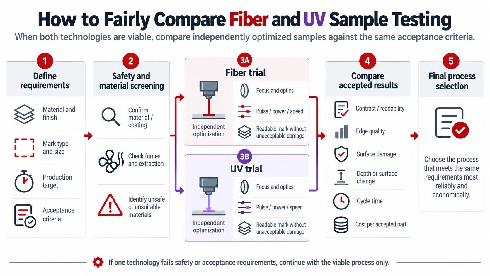
Define the Part, Mark and Pass/Fail Criteria Before Testing
Prepare a sample brief that describes the real workpiece and the acceptance conditions. Useful inputs include:
- Material and construction: alloy or resin grade, supplier or formulation when known, pigments/additives, coatings, wall thickness, geometry and starting surface finish.
- Mark definition: artwork or code file, actual content, overall dimensions, minimum feature requirements and intended location on the part.
- Required outcome: contrast, human or machine readability, any specified verification method or code grade, physical depth if required, and permanent or removable surface changes.
- Protection limits: permitted burrs, melting, deformation, cracking, coating removal, color shift or functional changes, including electrical and corrosion-related restrictions.
- 生産条件: downstream cleaning or wear exposure, expected volumes, part presentation, acceptable cycle time and how marks will be inspected.
Acceptance limits should be taken from the product specification and its intended use. Do not invent a general-purpose quality threshold just to complete the comparison.
Safety screening comes before process optimization. Confirm the actual polymer, coating and adhesive constituents—particularly possible PVC or other halogen-containing layers—before any trial. Evaluate laser-generated emissions and do not process an unidentified material until its hazards and the required controls have been assessed. OSHA’s laser-hazard guidance emphasizes ventilation for potentially hazardous fumes from laser-material interactions.
Run Fair Trials on Identical Substrates, but Optimize Each Process Separately
Use representative parts from the same material grade, surface treatment and preferably the same production lot. Keep the required artwork, marked area and inspection method the same. The systems do ではない need identical wattage, frequency or scan speed: a fair test allows each source to be tuned for the same required result.
Confirm that the usable marking field covers the complete artwork at the required focus and positioning tolerance. Flexible, curved or inconsistently presented parts may need fixtures or controlled support; include fixture loading, repositioning and refocusing time in the measured production cycle.
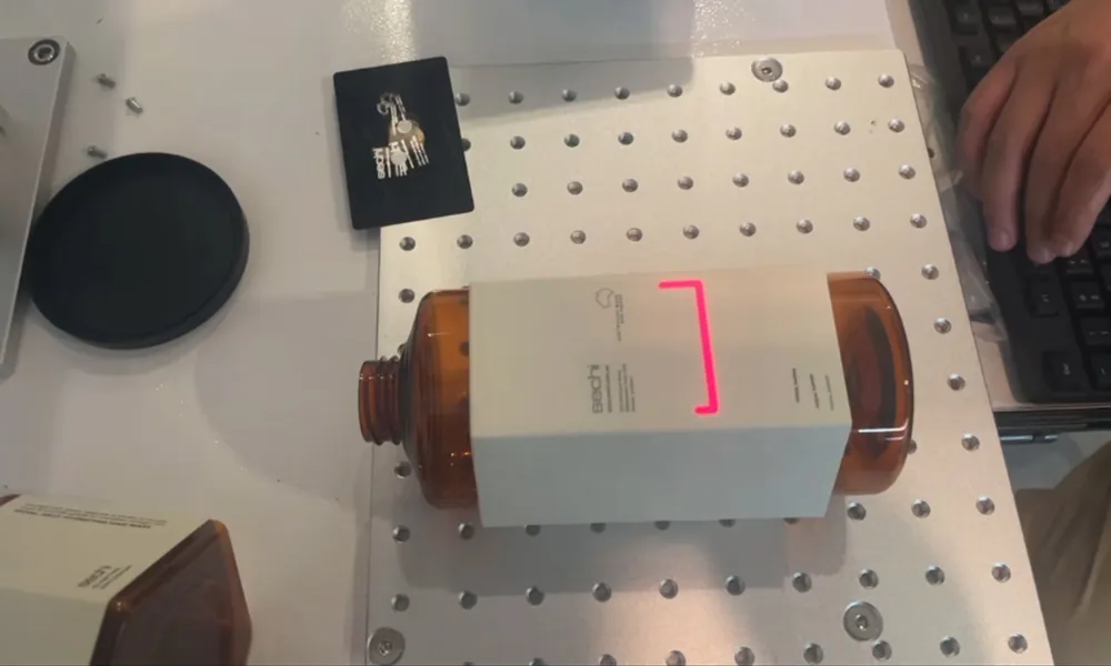
- Record the source and optics configuration and the starting condition of each sample.
- Adjust the relevant pulse, power, focus, scanning, hatch and pass settings within the equipment’s safe operating limits to identify a viable process window.
- Mark more than one representative sample and document settings, observations, rejects and any damage or code-quality failures.
- Inspect under the intended lighting or code-verification method; add magnified, surface, dimensional or functional checks wherever part integrity requires them.
Include handling or environmental tests if the specification demands durability. A single perfect-looking sample at one setting is weaker evidence than a process that passes repeatedly with reasonable tolerance for normal part variation.
Select the Route That Passes in Production, Not Just on a Demo Sample
If only one system meets all acceptance criteria, that is the stronger basis for the selection. If both pass, compare their repeatability, stable settings range, accepted-part cycle time, rejects, fixtures, integration needs and cost per accepted part. If neither passes, stop and reconsider the marking requirement or process rather than treating the comparison as a forced two-option purchase.
Once a viable process direction is established, compare ファイバーレーザーマーカー および UVレーザーマーカー by marking field, workpiece handling, safety configuration and integration needs. These product categories can narrow the machine format, but they do not replace testing on actual parts.
For a preliminary machine-configuration discussion with Zhuorui Laser, provide the actual part or drawing, material grade and surface finish, mark artwork, acceptance criteria and expected production rate. Those details make the discussion specific enough to identify a suitable trial direction; final suitability still depends on testing and approval against your requirements.