ファイバー対CO2レーザーマーキング:お使いの材料に適しているのはどちらですか?
ほとんどのむき出しの金属部品に直接マーキングする場合、ファイバーレーザーが通常はより適した出発点です。木材、紙、段ボール、および多くの皮革表面には、CO2レーザーが一般により適した選択です。エンジニアリングプラスチック、コーティング金属、ガラス、包装材料では判断はそれほど単純ではなくなり、表面の配合や必要なマークが材料名と同じくらい重要になることがあります。.
有用な問いは、単にどのレーザーが目に見えるマークを残せるかではありません。許容できる生産サイクル内で、実際の部品に必要なコントラスト、読みやすさ、表面状態、一貫性を生み出せるのはどのプロセスか、という点です。この違いが、出力定格や機械価格の話に入る前に、比較を導くべきです。.
ファイバーかCO2か:どちらを先に評価すべきですか?
レーザーが実際に接触する表面から始めます。未コーティングのステンレス鋼部品にシリアル番号またはデータマトリックスコードが必要な場合、ファイバーマーキングは金属を直接改質または除去できるため、論理的な最初の試行です。紙製カートンへの日付コード印字が作業であれば、材料が赤外波長によく反応するため、通常はCO2の方が適切な方法です。.
着色された陽極酸化アルミニウム製の銘板や成形プラスチック筐体の場合、選択はそれほど明確ではありません。このような場合、コーティング、顔料、添加剤、または表面仕上げが、どのレーザーが許容できる結果を生み出すかを左右する可能性があります。.
これらの違いから、実用的な原則が導かれます: 最初にテストするレーザーは、大まかな金属対非金属という区分ではなく、材料の露出表面と必要なマーキング効果に基づいて選びます。. 適切な最初の選択は不要な試行を減らしますが、生産を代表する部品での検証に代わるものではありません。.
ファイバーレーザーとCO2レーザーでは、なぜ材料へのマーキングの仕方が異なるのですか?
従来型 ファイバーレーザーマーカー 一般に、近赤外領域の1,064ナノメートル付近で動作します。多くの産業用CO2マーカーは10.6マイクロメートルで動作し、これははるかに長い赤外波長ですが、一部のシステムでは特定の基材向けに9.3マイクロメートルなどの代替波長を使用します。これらの波長は、金属、ポリマー、コーティング、有機材料に対して異なる相互作用をします。.
吸収されたレーザーエネルギーは、いくつかの種類の変化を引き起こす可能性があります。金属では、酸化物に基づく色のコントラストが生じたり、表面材料が少量失われたりすることがあります。ポリマーでは、変色、発泡、溶融、または層の除去が起こることがあります。有機表面では、局所的な熱分解によって暗くなる場合があります。結果は、材料の反応と供給エネルギーの両方に依存します。波長は何が可能かを決める助けになりますが、波長だけでは許容可能な結果を確立できません。.
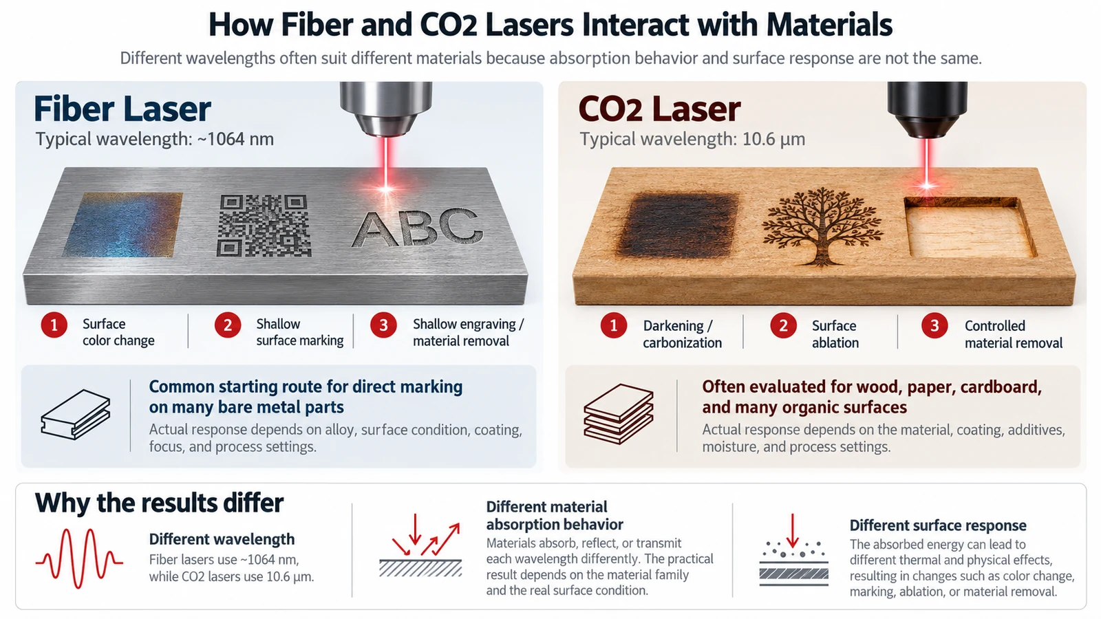
ビームの伝送、集光、パルス挙動、スキャン設定、および露光時間も重要です。波長が適切であっても、これらの条件によって、材料が制御された方法で反応するかどうか、およびマークがその合格基準を満たすかどうかが決まります。.
どの材料とマーキング結果が各レーザーに適しているか?
材料の適合性は、次の組み合わせとして理解するのが最も適切です 基材、表面状態、および要求される結果. ある仕上げ面で強いコントラストを生み出すレーザーでも、別の仕上げ面では弱いマークや過度な表面変化を生じさせる可能性があります。.
裸の金属:直接マーキング、コントラスト、彫刻
ファイバーレーザーは一般に、未コーティングのステンレス鋼、炭素鋼、アルミニウム、チタン、およびその他多くの産業用金属部品の直接マーキングにおける第一の選択肢です。合金とプロセス設定に応じて、別途マーキング剤を塗布することなく、目に見える色変化、浅い表面マーク、または凹んだ彫刻を作成できます。.
これらの結果は置き換え可能ではありません。部品が比較的平滑なままでなければならない場合、暗い表面マークはトレーサビリティコードに適している可能性があります。指定された彫刻深さや機械的摩耗へのより高い耐性が合格基準の一部である場合、凹んだマークが必要になることがあります。深さを達成するには通常、より多くの材料除去を伴い、処理時間が増加したり表面が変化したりする可能性があります。裸のアルミニウムでは、特定の黒色の色調がすべてのファイバー光源と仕上げで達成可能であると想定すべきではありません。コントラストは実際の合金と表面状態で確認する必要があります。.
従来のCO2マーカーは通常、裸の金属を直接彫刻するための実用的な選択肢ではありません。適切なマーキングペースト、スプレー、またはテープを使用すれば金属にマークを生成できる場合がありますが、それには準備と洗浄の工程が追加され、基材を直接変更するプロセスとは異なります。.
木材、紙、段ボール、革:表面の反応が重要
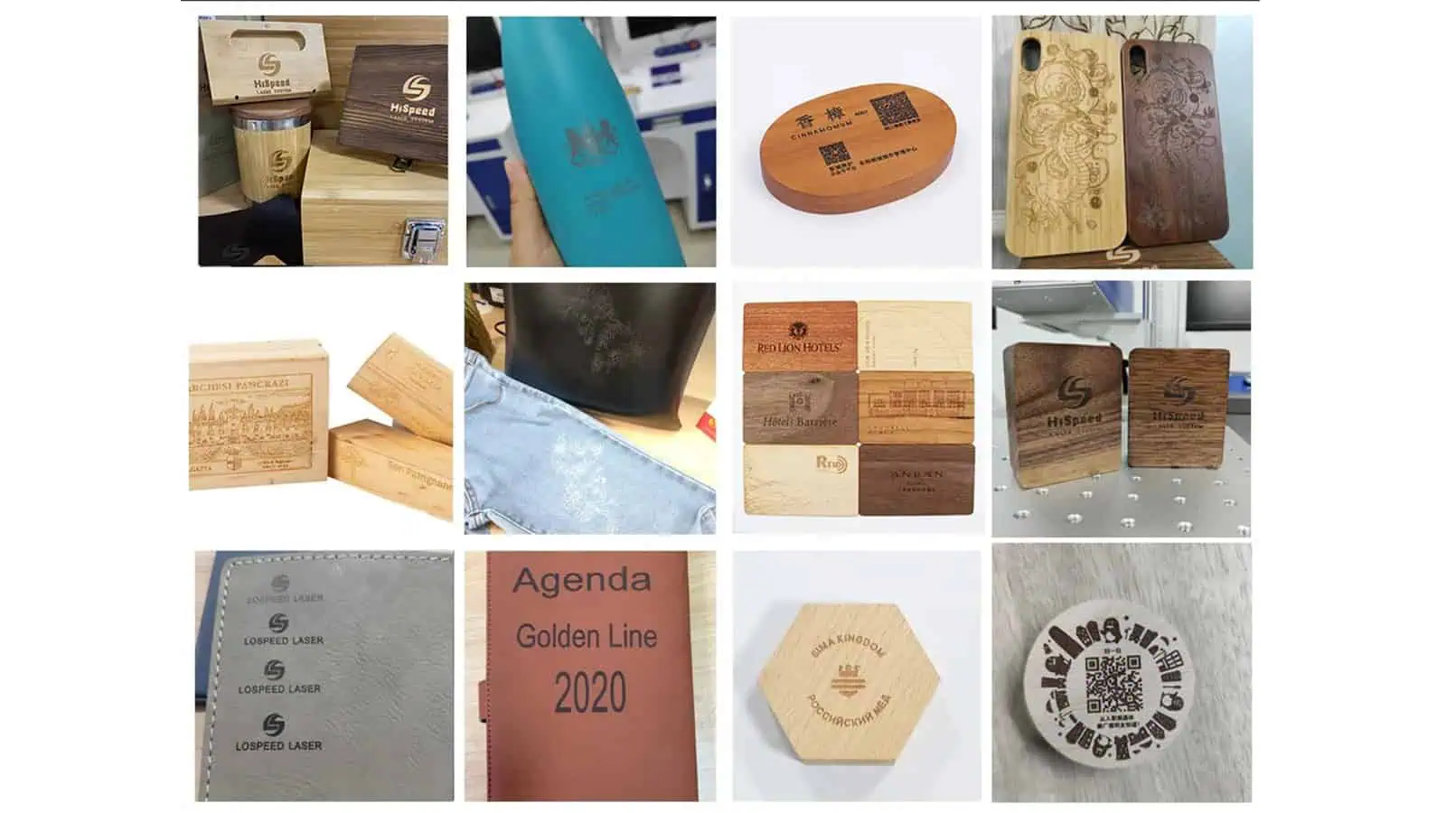
CO2レーザー 一般に、木材、紙、段ボール、および多くの革表面によく適合します。基材に応じて、局所的な暗色化、炭化、または制御された材料除去によって可視マークを作成できます。このため、CO2は包装コード、製品識別、および有機材料上の装飾的または機能的なマークの一般的な候補となります。.
課題はその反応を制御することです。より目立つ焼け跡が必ずしもより良いマークとは限りません。過剰なエネルギーは、炭化、すす、ぎざぎざの文字端、変形、または仕上げ表面への許容できない変化を引き起こす可能性があります。木目、紙のコーティング、革の仕上げ、色、および水分はすべて結果に影響を与える可能性があります。.

| 材料または表面 | ファイバーレーザー | CO2レーザー | 確認が必要な項目 |
|---|---|---|---|
| 未処理のステンレス鋼、鋼、アルミニウム、および同様の金属 | 通常、直接マーキングまたは彫刻の第一選択肢です | 裸金属への直接マーキングには一般に適していない | コントラスト、深さ、合金、仕上げ、および許容される表面変化 |
| 木材、紙、段ボール、および多くの皮革表面 | 通常は第一選択ではない | 通常は第一選択である | 暗色化、エッジ品質、焦げ、および材料損傷 |
| エンジニアリングプラスチック | 適切な配合とマーキング条件であれば可能 | 適切な配合とマーキング条件であれば可能 | 樹脂グレード、顔料、添加剤、色、および変形 |
| 陽極酸化処理、塗装、またはその他の方法でコーティングされた金属 | 表面層にマークを付けるか、表面層を改変する可能性がある | 特定の表面層にマークを付けるか、特定の表面層を除去する可能性がある | コーティングの種類、層の除去、下地材料、および保護要件 |
| ガラスおよびPET容器 | 一般に、標準的な透明表面では通常の最初の選択肢ではない | 選択されたガラスおよびPETマーキング用途の候補 | Wavelength, wall thickness, appearance, and structural integrity |
The table narrows the options, but it cannot resolve the difficult cases by itself. In particular, plastics and coated products require a closer look at which layer absorbs the beam and what the marking process is permitted to change.
When Do Plastics, Coatings, and Transparent Materials Change the Answer?
For these materials, the exposed surface may behave very differently from the base material named on a drawing. The following situations show why an initial recommendation sometimes needs closer evaluation.
Before testing an unfamiliar plastic, synthetic leather, or coated material, confirm its composition and laser-processing safety. PVC and some other halogen-containing materials can release hazardous or corrosive fumes under laser exposure and may be unsuitable for laser processing. Do not trial-mark an unidentified formulation simply to see whether a visible code can be produced; establish material suitability and the necessary fume controls first.

Plastics: Resin Grade, Color, and Additives Matter
“ABS,” “PC,” or “PP” is not enough information to predict a reliable laser mark. The actual formulation may include pigments, fillers, flame retardants, or laser-sensitive additives that change how strongly the part absorbs a given wavelength. Some formulations respond well to near-infrared fiber lasers; others may be more suitable for CO2 processing or require a different wavelength altogether.
The desired marking mechanism matters just as much. A laser might create a dark color change with little visible relief, produce a lighter foamed mark on a darker plastic, or remove a thin surface coating to expose a contrasting layer. Those results have different implications for appearance, texture, and functional surfaces. If the plastic melts, warps, becomes brittle, or loses code definition, a visible mark alone is not evidence of a suitable process.
For a molded housing or connector, a meaningful trial therefore needs the actual resin grade, color, additive package where available, and final surface finish. Testing a generic plastic sample does not establish that another formulation will behave the same way.
Coated Metals: Are You Marking the Coating or the Metal?
Consider a dark 陽極酸化アルミニウム tag. A laser can create a light mark by modifying or removing part of the colored surface layer. Both fiber and CO2 systems can be candidates for certain anodized finishes. But the fact that the part is made from aluminum does not mean the laser has deeply engraved bare aluminum underneath.
Painted or powder-coated parts present a related decision. If the goal is to reveal the base material or a contrasting layer, selective coating removal may provide the right appearance. If the coating serves a corrosion, electrical, or other protective purpose, removing it may be unacceptable even when the code is highly legible. The required outcome must be defined before choosing the process.
Glass, PET, and Thin Packaging: Visible Does Not Always Mean Acceptable
Transparency to visible light does not tell you how a material will respond to a CO2 laser. CO2 markers can produce frosted-looking marks on some glass and PET products, but the mechanism and acceptable process window are different. On glass, localized thermal effects can produce microfractures or surface changes; appearance must be evaluated alongside the risk of chipping or weakening the product.
On PET bottles, even the choice between CO2 wavelengths can matter. Systems operating near 9.3 micrometers may produce a shallower, foamed-looking effect on certain thin-walled PET containers, whereas a 10.6-micrometer process may remove more material. The appropriate choice depends on bottle construction and the required code. A readable date mark is not sufficient if it creates a weak point, pinhole, or other unacceptable change to the packaging.
Thin films and multilayer packaging deserve the same caution. The marking process must preserve any necessary barrier, sealing, and mechanical properties. Where neither fiber nor CO2 can meet the quality requirement without excessive surface change, another marking technology may need evaluation rather than forcing one of these two systems to work.
Which Is Faster or More Cost-Effective in Production?
There is no reliable answer to “Is fiber faster than CO2?” without specifying the material, mark, machine configuration, and production arrangement. A fiber laser may be a natural choice for high-volume metal traceability, while a CO2 coder may be well suited to moving cartons or bottles. Those strengths do not establish a universal speed ranking.
比較 accepted parts per hour, not a headline scan-speed figure alone. The actual cycle can include part presentation, positioning, focus adjustment, laser exposure, indexing, and any code verification. Mark size, fill pattern, contrast target, required depth, and the number of processing passes also affect the time needed for an acceptable result. A faster-looking trial is not better if the mark fails readability or durability checks.
Ownership cost also depends on the complete installation. The laser source design, optics, cooling requirements, extraction, guarding, fixtures, consumables, and maintenance environment all matter. In particular, a CO2 metal-marking process that relies on spray or paste adds handling steps that a direct fiber-metal process may avoid. Conversely, selecting fiber for a substrate that does not absorb its wavelength effectively can waste money regardless of the machine’s purchase price.
Only compare purchase and running costs after establishing which process can repeatedly meet the specification. Otherwise, the lower-priced machine may simply be the wrong machine.
How Do You Make the Final Choice and Validate the Mark?
The final choice should be based on a trial using production-representative parts and defined acceptance criteria. If both technologies are candidates, evaluate their marks against the same requirements before comparing their production fit.
Follow a Practical Selection Sequence
- Identify the exposed surface. Record the substrate, grade, color, finish, and whether the beam will contact bare material, a coating, or a multilayer structure.
- Define the required result. Specify the code or graphic, its size, target contrast or readability, depth if relevant, and any limits on visible or functional surface change.
- Choose the first trial route. Prioritize fiber for typical bare-metal marking and CO2 for many organic surfaces. Treat plastics, coatings, glass, and packaging as application-specific decisions.
- Test the actual part. Compare acceptable marking quality, edge definition, surface effects, and performance after any required cleaning, handling, or downstream process.
- Compare production fit. Once the marks pass, evaluate cycle time, handling, integration, extraction, guarding, and total operating requirements before settling on a machine configuration.
What Should a Sample Marking Test Confirm?
| 確認 | 解決すべき質問 |
|---|---|
| Actual material | Is the sample the specified grade, color, coating, and surface finish? |
| マーク仕様 | Does the result meet the required text, code size, contrast, and depth where specified? |
| 可読性 | Can the intended reader or scanner consistently read the mark under realistic conditions? |
| 表面健全性 | Are melting, cracking, excessive roughness, coating removal, or other changes within permitted limits? |
| 耐久性 | Does the mark remain acceptable after relevant cleaning, abrasion, handling, or downstream processing? |
| 量産再現性 | Can the process hold the required quality and cycle time with realistic positioning and part variation? |
If the same operation needs direct marks on bare-metal parts and codes on uncoated paperboard, do not assume that one conventional fiber or CO2 source is the best fit for both. Depending on the workflow, compare separate marking stations with a properly configured dual-source system; part handling, production volume, and the required results determine whether either arrangement makes sense.
If both technologies pass, select between them using the actual production trade-offs. If neither passes, reconsider the wavelength, marking mechanism, or material specification instead of compensating with more power alone. For a useful machine-selection review, provide the actual material and finish, a drawing or photograph of the marking area, the code artwork, the acceptance criteria, and the expected production rate.