どれを選ぶか: 3W、5W、10WのUVレーザーマーカー 単にレーザー出力を上げて購入するだけの問題ではありません。適切な選択とは、お使いの材料に許容できるマークを形成し、生産サイクルタイムを満たし、不要な設備コストをかけずに十分なプロセスマージンを確保できるマシンを選ぶことです。
小さく詳細なマークで生産要件が控えめな場合、3W UVレーザーで十分なことがあります。追加の出力によって処理時間を短縮できる、または使用可能なプロセスウィンドウを改善できる場合は、5Wマシンを評価する価値があります。マーキング作業量がより多く、追加の出力が有意義な生産上のメリットをもたらすことがテストで示された場合は、10Wシステムを検討する価値があります。
これらは出発点であり、固定された適用限界ではありません。10Wレーザーが自動的に3Wレーザーよりシャープなマークを生成したり、3倍速く動作したりするわけではありません。レーザー光源、パルス特性、光学系、材料、マーキングパターン、生産条件がすべて結果に影響します。
| UVレーザー出力 | 最初に検討すべきとき | 確認すべき事項 |
|---|---|---|
| 3W | 小さなマーク、微細なディテール、および中程度のマーキング作業量 | 必要なコントラスト、ディテール、再現性、サイクルタイム |
| 5W | より多くの処理マージン、またはマーキング時間の短縮の可能性を必要とするアプリケーション | 許容可能な3Wプロセスに対する測定可能な改善 |
| 10W | より高いマーキング作業量、より大きな塗りつぶしパターン、または要求の厳しい生産サイクル | 許容できない材料損傷を伴わない実際のスループット向上 |
最も信頼できる選定方法は、マーキング要件を明確にし、適切な装置構成を比較し、代表的なサンプルで候補を検証することです。
UVレーザー出力を選ぶ前に何を確認すべきですか?
ワット数を比較する前に、装置が何を達成する必要があるかを明確にしてください。2社のメーカーがどちらもプラスチック部品へのマーキングを必要としていても、一方は数分ごとに小さなシリアル番号を必要とし、他方は移動する生産ライン上で読み取り可能なコードを生成する必要があるかもしれません。これらは異なる設備選定の課題です。
材料、表面状態、損傷限界
UVレーザーマーキングで一般的に使用されるのは 355 nmの波長. です。多くのプラスチック、コーティング、敏感な表面との相互作用により、従来の赤外線レーザーマーキングでは過度な熱影響を引き起こす可能性がある用途で有用です。ただし、UVマーキングが熱や材料損傷をまったく受けないわけではありません。反応は実際のワークピースによって異なります。
プラスチック部品では、ポリマーグレード、顔料、充填剤、添加剤、表面テクスチャ、成形条件がマークのコントラストや加工挙動に影響を与える可能性があります。単に「ABS」または「ポリカーボネート」と記載された2つの部品でも、異なる設定が必要になる場合があります。
ガラスは別の懸念をもたらします。可視マークは実現できるかもしれませんが、過度の表面改質、微細亀裂、欠け、または機械的完全性の喪失は許容できない場合があります。
パワーを選択する前に、次を確認してください:
- 入手可能な場合は、正確な材料または配合。
- 表面色、コーティング、仕上げ、厚さ。
- マークが暗色、明色、つや消し、またはその他の方法で視覚的に明確である必要があるかどうか。
- 溶融、変色、亀裂、または表面変形が許容されるかどうか。
- マークが耐えなければならない洗浄、摩耗、化学薬品への暴露、または下流工程。
材料の説明だけでは、3W、5W、10Wのいずれで十分かを判断することはできません。プロセスのより詳しい説明については、当社の UVレーザーマーキング技術ガイド.
マークのサイズ、細部、要求品質
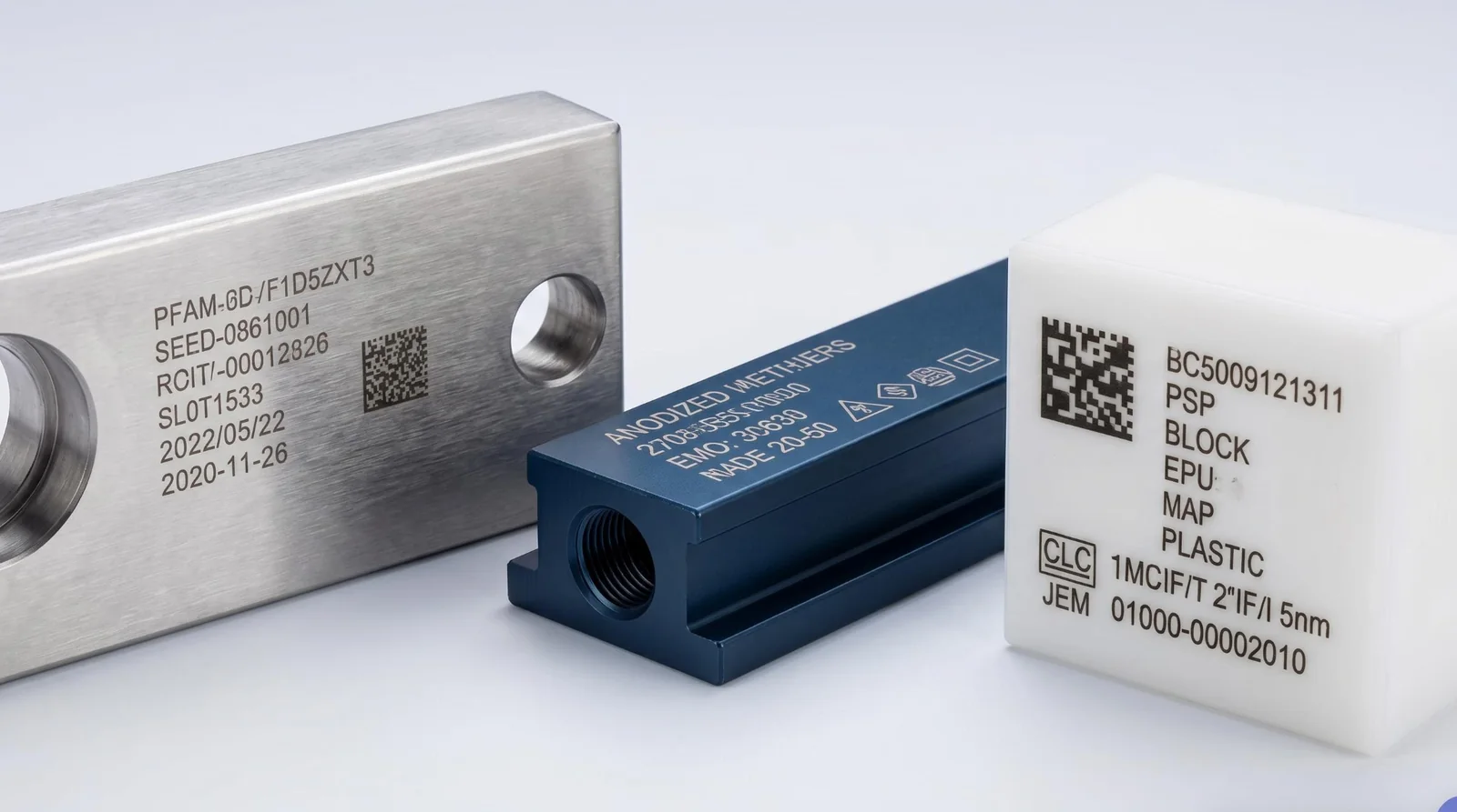
小さなシリアル番号と大きな塗りつぶしロゴでは、同じ材料上にあってもレーザーへの負荷が大きく異なる場合があります。小さな輪郭は限られた処理で済むことがありますが、塗りつぶしデザインでは間隔の狭い走査線が多数必要になります。塗りつぶし面積、要求されるコントラスト、またはパス数を増やすと、マーキング時間が長くなる可能性があります。
合格基準は試験前に定義する必要があります。テキストやグラフィックスの場合、有効な確認項目には、文字の判読性、エッジの鮮明さ、塗りつぶしの均一性、意図しない表面変化などがあります。
QRコードやData Matrixシンボルの場合、見た目だけでは十分ではありません。コードは、実際のサイズ、コントラスト、周囲の表面、想定される読み取り装置など、要求される読み取り条件を満たす必要があります。部品に繊細なコーティングがある場合、許容できる表面変化は、マークの見た目の濃さよりも重要になることがあります。
高出力レーザーが本質的に微細なディテールを提供するわけではありません。集光スポット、ビーム品質、フィールドレンズ、走査精度、材料の反応も、機械が生成できるものを決定します。
生産量と利用可能なサイクルタイム
生産需要は、バイヤーがより高いUVレーザー出力を検討する理由であることがよくあります。ただし、日々の生産量とレーザーマーキング時間は同じ指標ではありません。
完全な生産サイクルには、位置決め、ローディング、フォーカシングまたは高さ調整、マーキング、コード検証、アンロードが含まれる場合があります。これらの作業がサイクルの大部分を占める場合、レーザーオン時間を短縮しても、実際の生産量はほとんど改善しない可能性があります。
小さな識別マークをバッチで生産するワークステーションでは、3Wシステムで各マークを完了するのに十分な時間がある場合があります。マーキング可能な時間が短い生産ステーションでは、マーク自体が比較的小さくても、異なる処理能力が必要になる場合があります。
重要な問いは、単にスキャナーがどれだけ速く動けるかではありません。利用可能なサイクルタイム内で、システム全体が許容可能な部品を安定して生産できるかどうかです。
材料、アートワーク、マークサイズ、合格基準、予想生産量、目標サイクルタイムを含む基本的なマーキング仕様書を用意してください。これらの詳細により、出力比較が意味のあるものになります。
3W、5W、10WのUVレーザーでは実際に何が変わるのか?
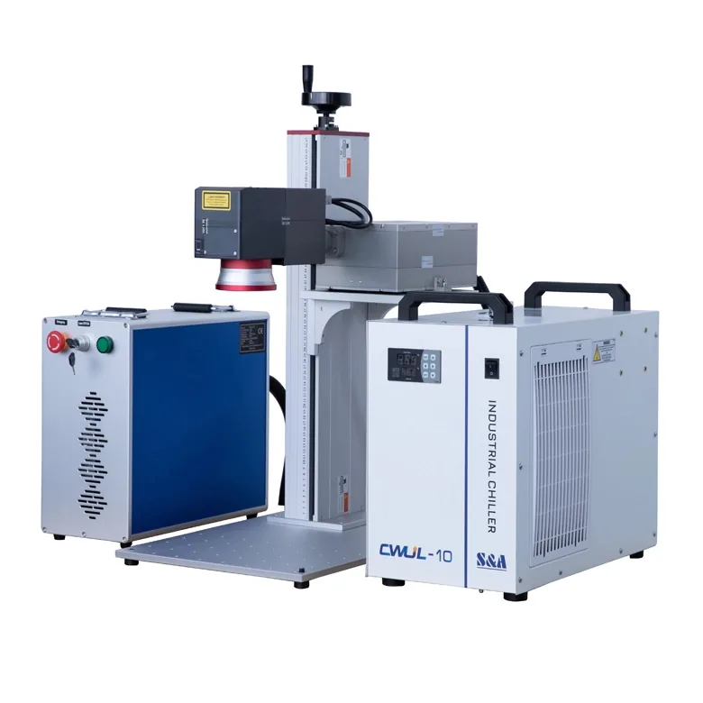
UVレーザーの仕様におけるワット数は通常、次を指します。 規定された動作条件下での定格平均光出力. これは装置全体で消費される電力を表すものではなく、個々のパルスで供給されるエネルギーを完全に表すものでもありません。
平均出力、パルスエネルギー、レーザー光源の違い
多くの産業用UVマーキングシステムは、パルス動作のダイオード励起固体レーザー光源を使用しています。その性能は定格出力だけに依存するものではありません。
パルス繰り返し周波数は、パルスがどの程度頻繁に放出されるかを示します。該当するパルス動作条件下では、 平均パルスエネルギーは、概ね平均光出力を繰り返し周波数で割った値です. パルス幅、ビーム品質、レーザーの出力対周波数特性も加工に影響します。光源は全周波数範囲で定格出力を維持できない場合があります。
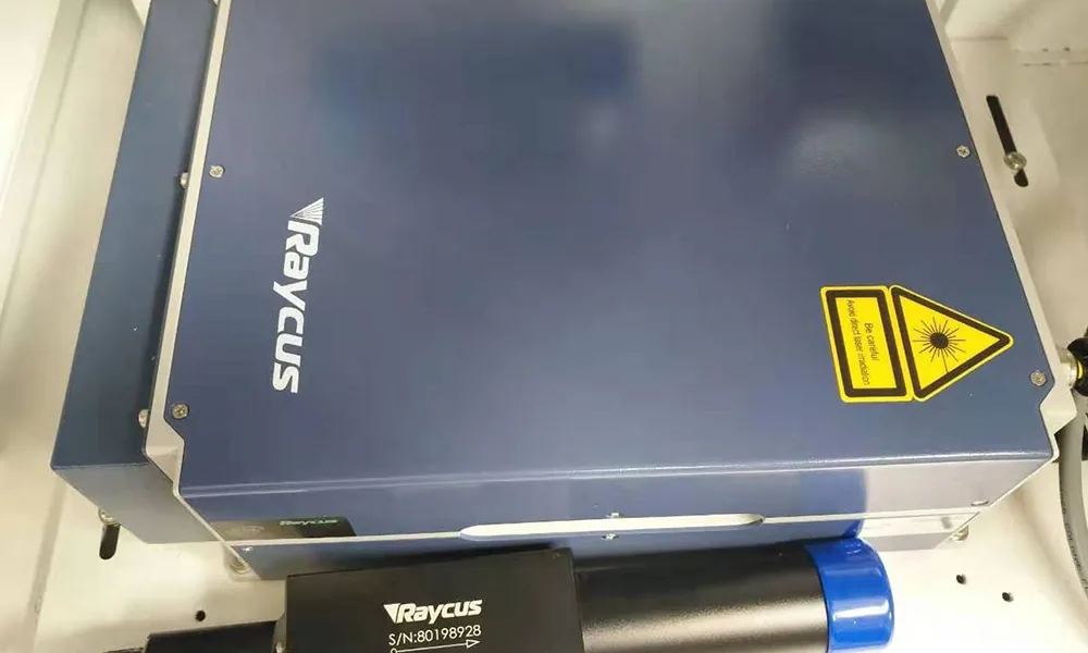
メーカーのデータは、正確なモデルが重要である理由を示しています。以下は選定された JPT UVレーザー光源の仕様, であり、Zhuorui Laser が提供する完成マーキング機または標準構成の測定性能値ではありません。
| レーザー光源モデル | 公開されている出力条件 | 記載の繰り返し周波数範囲 | 光源冷却 |
|---|---|---|---|
| SEAL-355-3E | 30 kHzで3 W超 | 20–200 kHz | 水冷式 |
| SEAL-355-5E | 40 kHzで5 W超 | 20–200 kHz | 水冷式 |
| SEAL-355-10S | 60 kHzで10 W超 | 40–300 kHz | 水冷式 |
出典:JPTの SEAL 355-3/5 仕様 および SEAL 355-10/15/20/30 仕様. 数値は、記載された レーザー光源 を指定された条件で示したものであり、マーキング速度の比例的な差異を立証するものではありません。
冷却方法も光源ファミリーによって異なります。例えば、JPTの LARK 355-3/5シリーズ 空冷式の3Wモデルと5Wモデルを含みますが、表内のSEALモデルは水冷式を使用しています。完成機は、搭載されるレーザー光源に合わせて構成する必要があります。
マーキング速度と利用可能な加工マージン
現在のプロセスが、許容可能なマークに利用できるエネルギーによって制限されている場合、レーザー出力を追加すると役立つことがあります。
指定されたコントラストに達するために複数回のパスを必要とする塗りつぶしパターンを考えてみます。適切な材料とレーザー条件のもとでは、より高出力のシステムにより、スキャン速度、繰り返し周波数、パスの異なる組み合わせが可能になり、総マーキング時間を短縮できる場合があります。
その改善が保証されるわけではありません。材料が追加のエネルギー投入に耐えられない可能性があります。光源が異なるパルス周波数で定格出力を出す可能性があります。または、スキャナー、集光条件、生産ハンドリングがすでにサイクルを制限している可能性があります。したがって、平均レーザー出力を2倍にしても、許容される生産量が2倍になるわけではありません。
加工マージンも重要です。非常に狭いパラメータ範囲でのみ良好な結果を出す機械は、材料や操作の現実的な変動にわたって必要な結果を維持する機械よりも、生産に適さない可能性があります。
有用な出力アップグレードは、少なくとも1つの関連する成果を改善する必要があります。許容されるマーキング速度、使用可能な加工マージン、または他の方法では満たすのが困難なマーキング要件への対応能力です。
高出力が自動的に高品質を意味するわけではない理由
最も見栄えの良いマークが、必ずしも利用可能な最高出力で作られるとは限りません。
熱に敏感なポリマーでは、過剰なエネルギー集中により変色、溶融、盛り上がったエッジ、その他の望ましくない変化が生じる可能性があります。ガラスでは、割れや表面損傷を抑えるためにプロセスを慎重に制御する必要がある場合があります。逆に、適切なプロセスウィンドウ内で動作するより高定格のレーザーが、低出力モデルより自動的に精度が低いわけではありません。
関連する要因には、集光スポットと光学系、パルス特性とエネルギー分布、スキャン速度、パルス重なり、ハッチ間隔、材料の吸収と熱応答、およびマーキングフィールド全体での焦点変動が含まれます。
精度が主要な要件である場合は、ワット数を品質の代替として扱うのではなく、意図した検査条件下で実際のマークを比較してください。より詳しい説明については、次を参照してください レーザー出力が唯一の要因ではない理由.
用途に応じてどのUVレーザー出力をテストすべきですか?
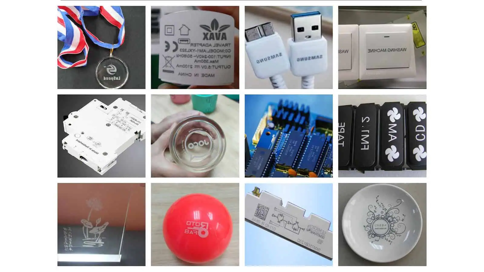
UV出力を候補として絞り込む最も有用な方法は、すべての材料に固定のワット数を割り当てるのではなく、マーキング作業を考慮することです。次のマトリクスは初期テストの方向性を示すものであり、材料適合性を保証するものではありません。
| マーキング作業 | 候補の比較 | 主な受入判断の問い |
|---|---|---|
| 小さな文字またはコンパクトな識別マーク | 3Wから開始し、必要に応じて5Wを比較 | マークは品質とサイクルタイムの要件を満たしていますか? |
| 日常的なプラスチック部品のコーディング | 3Wと5Wを比較 | 追加のパワーで許容できる出力は向上しますか? |
| より大きな塗りつぶしロゴや要求の厳しいマーキング作業 | 5Wと10Wを比較する。必要に応じて3Wのベースラインを維持する | 許容できない表面変化なしで時間は短縮されますか? |
| ガラスやその他の損傷に敏感な表面 | 材料とマークを確認した後に候補を選択する | 許容できない欠陥なしで必要な効果を達成できますか? |
| 短いマーキング時間枠、または可動部へのコーディング | モーションおよび制御構成と併せて出力を試験する | システム全体は生産速度で品質を維持できますか? |
3つ 例示的なエンジニアリングシナリオ これらの判断がどのように異なるかを示します。これらは選択ロジックの例であり、 記録された顧客試験や実測されたZhuorui Laserの結果ではありません.
シナリオ1:電子機器のプラスチックハウジングへの微細な識別マーク. Suppose a molded housing requires a compact serial number or Data Matrix symbol without damaging the surrounding plastic. Begin by checking whether a 3W UV system can produce an acceptable mark within the available cycle time. If it can do so repeatedly with sufficient process margin, more power may offer little benefit. If quality is acceptable but the processing time is too long, comparing a suitable 5W configuration becomes reasonable. Judge both the code readability and surface condition, not simply which sample looks darker.
Scenario 2: A larger filled logo on a coated polymer component. A filled design may require substantially more scan coverage than a few small characters. Depending on the coating and target appearance, a 5W system may complete the accepted pattern faster than a 3W machine. If the required cycle time remains out of reach, a suitable 10W candidate can be tested. Check coating integrity, edge quality, uniformity, and whether the supposed speed improvement remains when only acceptable results are counted.
Scenario 3: Variable-data coding at a production station. A manufacturer may need changing codes within a short available marking window. If laser-on time is the verified bottleneck, comparing higher power could be justified. If the constraint comes from part positioning, trigger timing, data handling, or motion, increasing laser power will not correct the underlying cause. A machine-side review should cover marking time, positioning, control signals, data content, and verification. Flying or online marking needs configuration-specific confirmation.
Similar-looking applications may therefore justify different power choices. The actual acceptance requirement—not the material name or wattage alone—controls the shortlist.
When Is a 5W or 10W UV Laser Worth the Extra Cost?
A higher-power UV laser marking machine may cost more, but the difference between quotations is not determined by laser power alone. The more useful question is whether the proposed configuration delivers enough additional value for the actual application.
Compare Complete Machine Configurations, Not Wattage Alone
Two machines with similar cabinets and the same advertised power may contain different laser sources, optics, cooling systems, controllers, and accessories. Before comparing prices, request quotations that clearly identify:
- レーザー光源: Brand, exact model, rated operating conditions, and supported parameters.
- Marking optics: Galvo scanner, field lens, marking area, and working-distance requirements.
- Cooling: Air- or water-cooled configuration and any supporting equipment required.
- 制御: Software, controller, variable-data functions, and required interfaces.
- Workpiece handling: Fixtures, positioning aids, and any installed rotary or vision functions.
- 安全対策と排気: Actual enclosure, interlocks, and fume-control provisions.
- Delivery scope: Computer, accessories, commissioning, documentation, spare parts, and support terms.
A 5W quotation with a better-matched optical system and more suitable machine configuration may be more valuable than a nominally higher-powered system with the wrong marking field or missing production requirements. A cooling system or optional module should be evaluated as part of the actual equipment package, not assumed to be included because of wattage.
Compare Upgrade Cost Against Accepted Production Output
Power upgrades become easier to justify when they solve a measurable production problem. If a 3W machine produces acceptable marks at the required output rate, a 5W option may not generate enough additional value to justify its cost.
When an acceptable 3W process cannot meet the production target, test whether a 5W configuration improves the completed process sufficiently. A 10W system becomes attractive when the additional output is usable, the material remains within acceptable limits, and the gain matters to production.
Compare accepted parts produced over the required operating period, changes in complete cycle time, rejected marks and rework, recurring operating costs, and any justified need for future capacity. Higher power only adds useful capacity if the process can actually benefit from it.
There is no reliable universal price premium or payback period for moving from 3W to 5W or 10W. Those figures require specific equipment quotations and validated operating data.
How to Compare 3W, 5W, and 10W UV Lasers in a Sample Test
A sample test should answer a purchasing question, not merely demonstrate that a laser can leave a visible mark. The purpose is to determine which proposed configuration meets the same production requirements at an acceptable cost.
Use Representative Workpieces and the Same Acceptance Criteria
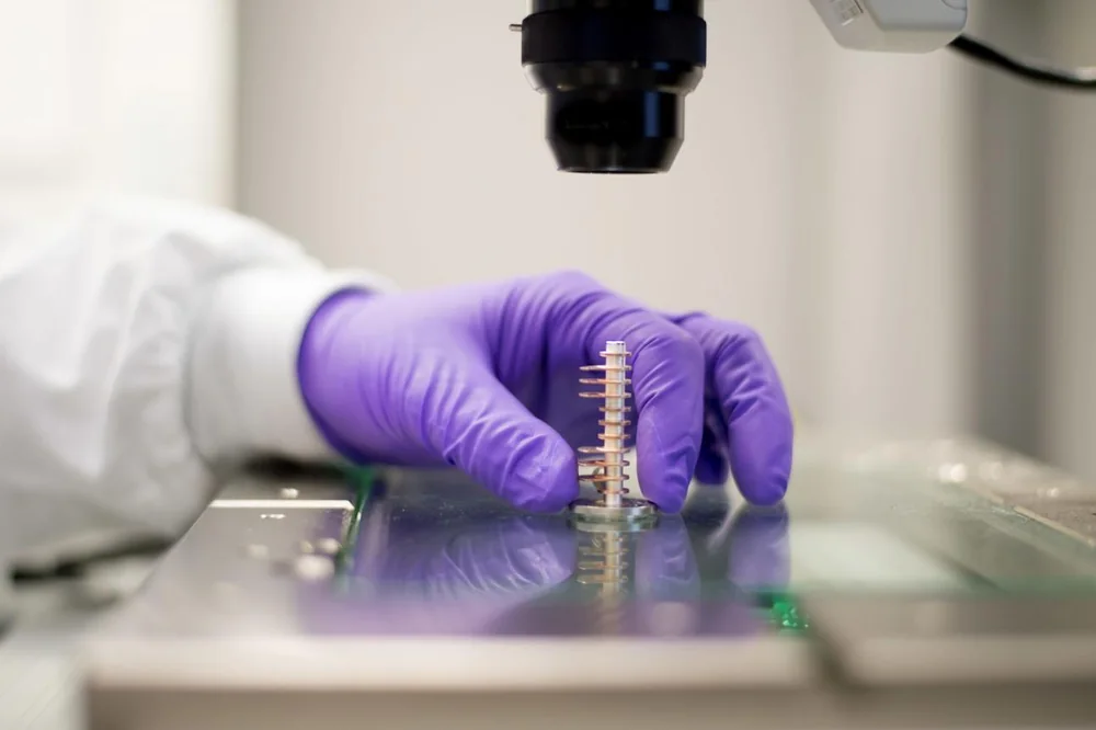
Use production-representative samples wherever possible. If the material has multiple grades, finishes, colors, or coatings, include the variations that could change marking behavior.
Each candidate should be evaluated against the same required task: identical marking content and intended dimensions; the same quality and readability criteria; applicable surface-damage limits; production cycle-time requirements; and comparable inspection methods.
For a Data Matrix code, compare whether each candidate produces an acceptable, readable symbol under the intended reader and inspection conditions. A visually darker symbol should not automatically be considered better if its geometry or surrounding material is damaged.
Optimize Each Laser Within Its Supported Process Window
A fair comparison does not necessarily mean forcing every laser to use identical operating settings. Different models may have different rated frequency ranges, pulse characteristics, and output behavior. Applying the same nominal frequency, software power percentage, and scan speed across all machines could unfairly disadvantage one system.
Instead, optimize each candidate within its supported range to meet the same acceptance criteria. Record the installed source model, optics, marking field, focus conditions, pulse frequency, scan speed, hatch spacing, and number of passes where relevant.
If the objective is to isolate laser-source power, control other influential conditions as closely as practical. If the objective is to choose between complete machines, compare their best validated production-ready configurations and document significant hardware differences. A complete-machine comparison can establish which configuration suits the task, but not necessarily that wattage alone caused the result.
Compare Quality, Repeatability, and Complete Cycle Time
Do not base a purchase decision on a single successful mark. Use repeated samples under representative working conditions. Depending on the application, inspect text readability, code verification, contrast, uniformity, surface damage, and any required durability after handling.
| 記録項目 | What to document |
|---|---|
| ワークピース | Material grade, batch, color, coating, thickness, and relevant geometry |
| マーキング要件 | Artwork or code, size, location, and acceptance criteria |
| マシン構成 | Source model, optical system, field size, cooling, and relevant installed functions |
| Process settings | Frequency, scan speed, passes, focus, and other relevant parameters |
| マーク品質 | Pass/fail outcome, readability, visual defects, and required durability checks |
| Processing time | Laser-only marking time and complete production cycle time |
| 再現性 | Results across repeated samples and relevant production variation |
| 最終判断 | Whether the configuration meets quality, throughput, and cost requirements |
Compare candidates using accepted output, not the maximum speed at which they can produce any visible mark. If a higher-powered system improves production performance, the gain must still justify the complete-machine configuration and cost.
For further preparation, see the サンプルマーキング試験チェックリスト.
How to Make the Final 3W, 5W, or 10W Selection
The final decision should follow validated marking requirements rather than a fixed rule that every buyer must progress from 3W to 5W and then to 10W.
- Choose a suitable 3W configuration when it meets the specified quality, cycle time, repeatability, and production-margin requirements. There is no automatic need to upgrade.
- Choose a suitable 5W configuration when testing shows a meaningful improvement in accepted processing efficiency or operating margin that justifies its additional cost.
- Consider a 10W configuration when a verified power-related throughput or processing limitation makes the additional output useful and the marking quality remains acceptable.
- Reconsider the process instead of increasing power when results are limited by material response, focus, optics, positioning, or excessive surface damage.
Some projects justify testing 10W alongside a lower-power candidate from the beginning. The sequence is not mandatory; the acceptance criteria are.
For a useful machine recommendation, prepare representative workpieces or material specifications, marking artwork, marking area, target result, production quantity, and available cycle time. A supplier can then review appropriate source and machine configurations and validate samples before purchase.
Explore the available UVレーザーマーカー または request an application-based quotation with your marking requirements.
Frequently Asked Questions About 3W, 5W, and 10W UV Lasers
Is a 10W UV Laser Marking Machine Always Water-Cooled?
Do not assume the cooling configuration from wattage alone. Many industrial 10W UV laser sources, including the published JPT SEAL models referenced above, use water cooling, but the required method must be confirmed for the exact source and complete machine. Lower-power UV sources can also be water-cooled, while some 3W and 5W models are air-cooled.
Is UV Laser Output Power the Same as Machine Power Consumption?
No. A 3W, 5W, or 10W rating generally refers to the laser’s optical output power under specified conditions, not complete-machine electricity consumption. Total consumption also depends on the source electronics, power supply, controller, computer, cooling system, and installed equipment. Request the complete machine’s electrical specifications when assessing operating costs or installation requirements.
Can a 3W UV Laser Marking Machine Be Upgraded to 5W or 10W Later?
An upgrade may be possible, but it is not necessarily a simple source replacement. A new laser source must be compatible with the power supply, controller, optical arrangement, cooling, mounting structure, and safety provisions. Recalibration and sample validation may also be needed. If future upgrading matters, ask the supplier whether the proposed platform supports the intended configuration and whether the change would be technically and economically reasonable.