Choosing between a 3W, 5W, and 10W UV laser marking machine is not simply a matter of buying more laser power. The right choice is the machine that produces an acceptable mark on your material, meets your production cycle time, and provides sufficient process margin without unnecessary equipment cost.
For small, detailed marks with modest production requirements, a 3W UV laser may be sufficient. A 5W machine becomes worth evaluating when additional power could reduce processing time or improve the usable process window. A 10W system deserves consideration when the marking workload is higher and testing demonstrates that the additional power delivers a meaningful production benefit.
These are starting points, not fixed application limits. A 10W laser does not automatically produce a sharper mark or operate three times faster than a 3W laser. The laser source, pulse characteristics, optics, material, marking pattern, and production conditions all influence the result.
| UV laser power | When to consider it first | What to verify |
|---|---|---|
| 3W | Small marks, fine details, and modest marking workloads | Required contrast, detail, repeatability, and cycle time |
| 5W | Applications needing more processing margin or potentially shorter marking time | Measurable improvement over an acceptable 3W process |
| 10W | Higher marking workloads, larger filled patterns, or demanding production cycles | Actual throughput gain without unacceptable material damage |
The most reliable selection method is to define your marking requirements, compare suitable machine configurations, and validate the candidates on representative samples.
What Should You Check Before Choosing UV Laser Power?
Before comparing wattage, identify what the machine must accomplish. Two manufacturers may both need to mark plastic components, yet one may require a small serial number every few minutes while the other must produce readable codes on a moving production line. Those are different equipment-selection problems.
Material, Surface Condition, and Damage Limits
UV laser marking commonly uses a 355 nm wavelength. Its interaction with many plastics, coatings, and sensitive surfaces makes it useful for applications where conventional infrared laser marking may cause excessive thermal effects. However, UV marking is not automatically free from heat or material damage. The response depends on the actual workpiece.
For plastic components, the polymer grade, pigments, fillers, additives, surface texture, and molding conditions can affect mark contrast and processing behavior. Two parts described simply as “ABS” or “polycarbonate” may require different settings.
Glass introduces other concerns. A visible mark may be achievable, but excessive surface modification, microcracking, chipping, or loss of mechanical integrity may be unacceptable.
Before selecting power, confirm:
- The exact material or formulation, where available.
- Surface color, coating, finish, and thickness.
- Whether the mark must be dark, light, frosted, or otherwise visually distinct.
- Whether melting, discoloration, cracking, or surface deformation is permitted.
- Any cleaning, abrasion, chemical exposure, or downstream process the mark must survive.
The material description alone cannot establish whether 3W, 5W, or 10W will be sufficient. For a broader explanation of the process, see our UV laser marking technology guide.
Mark Size, Detail, and Required Quality
A small serial number and a large filled logo can create very different laser workloads, even when they appear on the same material. A small outline may require limited processing, while a filled design involves many closely spaced scan lines. Increasing the filled area, the required contrast, or the number of passes can increase marking time.
The acceptance criteria should be defined before testing. For text and graphics, useful checks include character legibility, edge definition, fill uniformity, and unwanted surface changes.
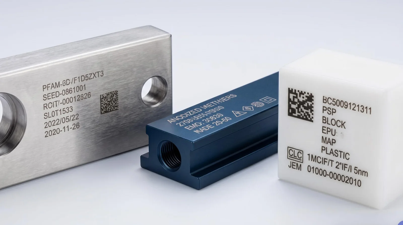
For QR codes or Data Matrix symbols, visual appearance alone is not sufficient. The code must meet the required reading conditions, including its actual size, contrast, surrounding surface, and intended reader. If the part has a delicate coating, the acceptable surface change may matter more than how dark the mark appears.
A higher-power laser does not inherently provide finer details. The focused spot, beam quality, field lens, scanning accuracy, and material response also determine what the machine can produce.
Production Volume and Available Cycle Time
Production demand is often the reason buyers consider a higher UV laser power. However, daily output and laser marking time are not the same measurement.
The complete production cycle may include positioning, loading, focusing or height adjustment, marking, code verification, and unloading. When these operations dominate the cycle, reducing the laser-on time may deliver little improvement in actual output.
A workstation producing small identification marks in batches may have enough time to complete each mark with a 3W system. A production station with a short marking window may require a different processing capability, even when the mark itself is relatively small.
The relevant question is not simply how fast the scanner can move. It is whether the complete system can consistently produce acceptable parts within the available cycle time.
Prepare a basic marking brief containing the material, artwork, mark size, acceptance criteria, expected production volume, and target cycle time. These details make the power comparison meaningful.
What Actually Changes Between 3W, 5W, and 10W UV Lasers?
The wattage in a UV laser specification usually refers to rated average optical output power under defined operating conditions. It does not represent the electrical power consumed by the complete machine, nor does it fully describe the energy delivered by individual pulses.
Average Power, Pulse Energy, and Laser Source Differences
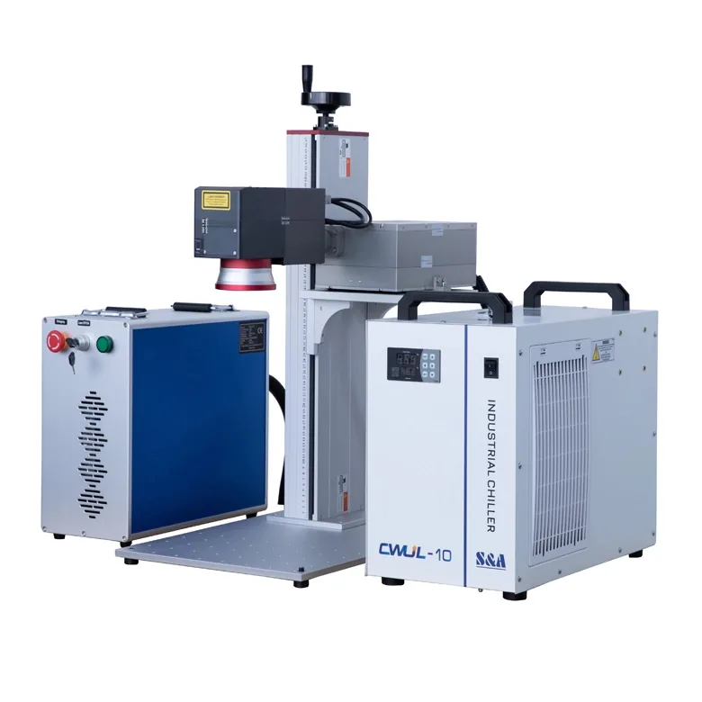
Many industrial UV marking systems use pulsed, diode-pumped solid-state laser sources. Their performance depends on more than rated output power.
The pulse repetition rate indicates how frequently pulses are emitted. Under the applicable pulsed operating conditions, average pulse energy is approximately average optical power divided by repetition frequency. Pulse width, beam quality, and the laser’s power-versus-frequency behavior also affect processing. The source may not maintain its rated output power across the entire frequency range.
Manufacturer data illustrates why the exact model matters. The following are selected JPT UV laser-source specifications, not measured performance figures for complete marking machines or the standard configurations supplied by Zhuorui Laser.
| Laser source model | Published output condition | Listed repetition-frequency range | Source cooling |
|---|---|---|---|
| SEAL-355-3E | >3 W at 30 kHz | 20–200 kHz | Water-cooled |
| SEAL-355-5E | >5 W at 40 kHz | 20–200 kHz | Water-cooled |
| SEAL-355-10S | >10 W at 60 kHz | 40–300 kHz | Water-cooled |
Sources: JPT’s SEAL 355-3/5 specifications and SEAL 355-10/15/20/30 specifications. The figures describe the listed laser sources at specified conditions; they do not establish proportional marking-speed differences.
Cooling also varies by source family. For example, JPT’s LARK 355-3/5 series includes air-cooled 3W and 5W models, while the SEAL models in the table use water cooling. The complete machine must be configured for its installed laser source.
Marking Speed and Available Processing Margin
Additional laser power can be useful when the current process is limited by the energy available for an acceptable mark.
Consider a filled pattern that requires multiple passes to reach the specified contrast. Under suitable material and laser conditions, a higher-power system may support a different combination of scan speed, repetition frequency, and passes that reduces total marking time.
That improvement is not guaranteed. The material may not tolerate additional energy deposition; the source may deliver its rated power at a different pulse frequency; or the scanner, focusing conditions, and production handling may already be limiting the cycle. Doubling average laser power therefore does not mean doubling accepted production output.
Processing margin also matters. A machine that produces a good result only within a very narrow parameter range may be less suitable for production than one that maintains the required result across realistic variations in material and operation.
A useful power upgrade should improve at least one relevant outcome: accepted marking speed, usable process margin, or the ability to meet an otherwise difficult marking requirement.
Why Higher Power Does Not Automatically Mean Better Quality
The best-looking mark is not necessarily produced at the highest available power.
On a heat-sensitive polymer, excessive energy concentration may cause discoloration, melting, raised edges, or other unwanted changes. On glass, the process may need careful control to limit cracking and surface damage. Conversely, a higher-rated laser operated within a suitable process window is not automatically less precise than a lower-power model.
The relevant factors include the focused spot and optical system; pulse characteristics and energy distribution; scan speed, pulse overlap, and hatch spacing; material absorption and thermal response; and focus variation across the marking field.
When precision is the dominant requirement, compare the actual marks under the intended inspection conditions rather than treating wattage as a substitute for quality. For a broader explanation, see why laser power is not the only factor.
Which UV Laser Power Should You Test for Your Application?
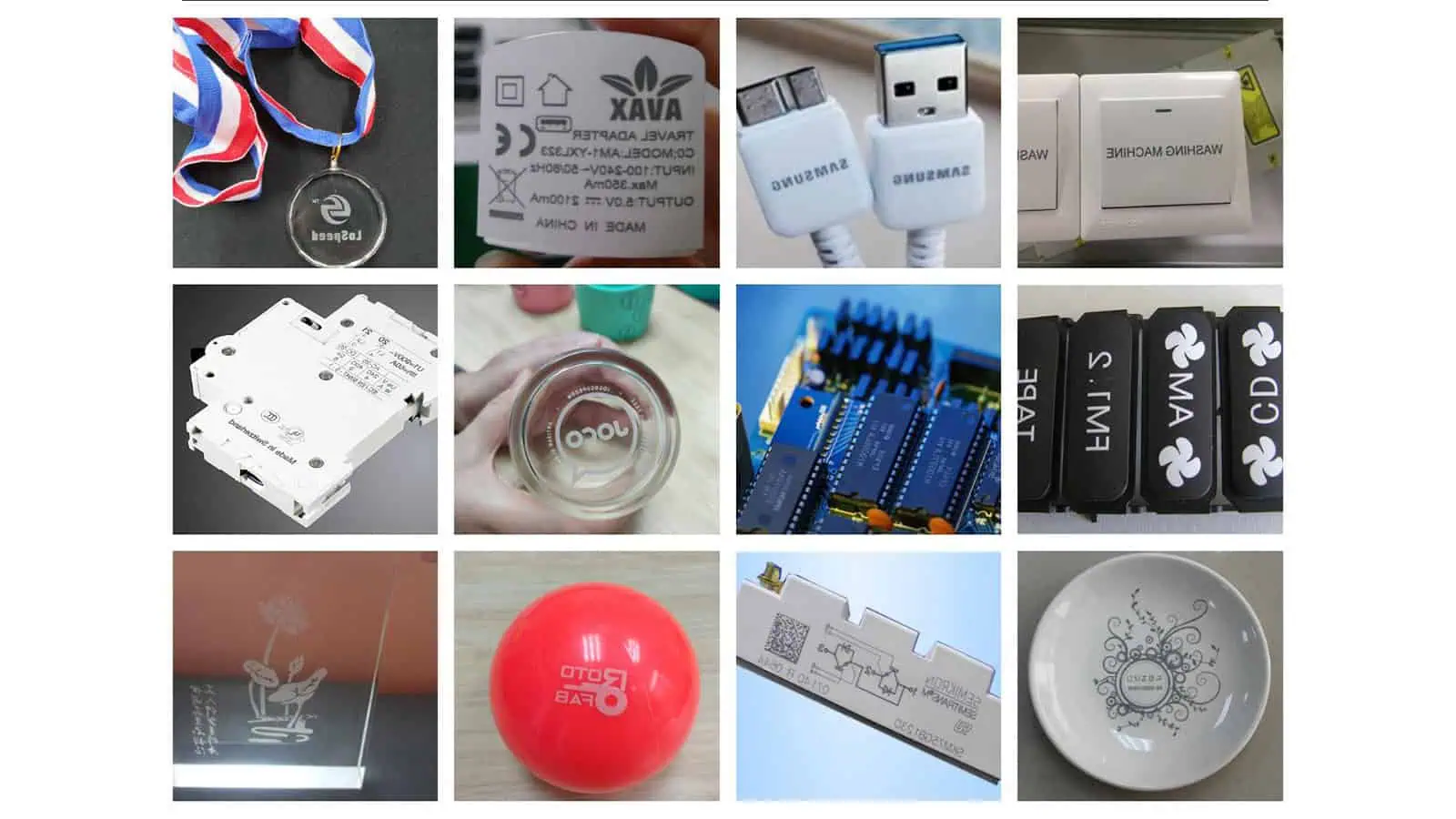
The most useful way to shortlist UV power is to consider the marking task rather than assign a fixed wattage to every material. The following matrix suggests initial testing directions, not material-compatibility guarantees.
| Marking task | Candidate comparison | Main acceptance question |
|---|---|---|
| Small characters or compact identification marks | Begin with 3W; compare 5W if needed | Does the mark meet quality and cycle-time requirements? |
| Routine plastic-part coding | Compare 3W and 5W | Does additional power improve accepted output? |
| Larger filled logos or demanding marking workloads | Compare 5W and 10W; retain a 3W baseline when useful | Is time reduced without unacceptable surface changes? |
| Glass or other damage-sensitive surfaces | Select candidates after reviewing the material and mark | Can the required effect be achieved without unacceptable defects? |
| Short marking windows or moving-part coding | Test power together with motion and control configuration | Can the complete system maintain quality at production speed? |
Three illustrative engineering scenarios show how these decisions differ. They are examples of selection logic, not recorded customer tests or measured Zhuorui Laser results.
Scenario 1: Fine identification marks on an electronic plastic housing. Suppose a molded housing requires a compact serial number or Data Matrix symbol without damaging the surrounding plastic. Begin by checking whether a 3W UV system can produce an acceptable mark within the available cycle time. If it can do so repeatedly with sufficient process margin, more power may offer little benefit. If quality is acceptable but the processing time is too long, comparing a suitable 5W configuration becomes reasonable. Judge both the code readability and surface condition, not simply which sample looks darker.
Scenario 2: A larger filled logo on a coated polymer component. A filled design may require substantially more scan coverage than a few small characters. Depending on the coating and target appearance, a 5W system may complete the accepted pattern faster than a 3W machine. If the required cycle time remains out of reach, a suitable 10W candidate can be tested. Check coating integrity, edge quality, uniformity, and whether the supposed speed improvement remains when only acceptable results are counted.
Scenario 3: Variable-data coding at a production station. A manufacturer may need changing codes within a short available marking window. If laser-on time is the verified bottleneck, comparing higher power could be justified. If the constraint comes from part positioning, trigger timing, data handling, or motion, increasing laser power will not correct the underlying cause. A machine-side review should cover marking time, positioning, control signals, data content, and verification. Flying or online marking needs configuration-specific confirmation.
Similar-looking applications may therefore justify different power choices. The actual acceptance requirement—not the material name or wattage alone—controls the shortlist.
When Is a 5W or 10W UV Laser Worth the Extra Cost?
A higher-power UV laser marking machine may cost more, but the difference between quotations is not determined by laser power alone. The more useful question is whether the proposed configuration delivers enough additional value for the actual application.
Compare Complete Machine Configurations, Not Wattage Alone
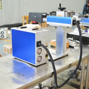
Two machines with similar cabinets and the same advertised power may contain different laser sources, optics, cooling systems, controllers, and accessories. Before comparing prices, request quotations that clearly identify:
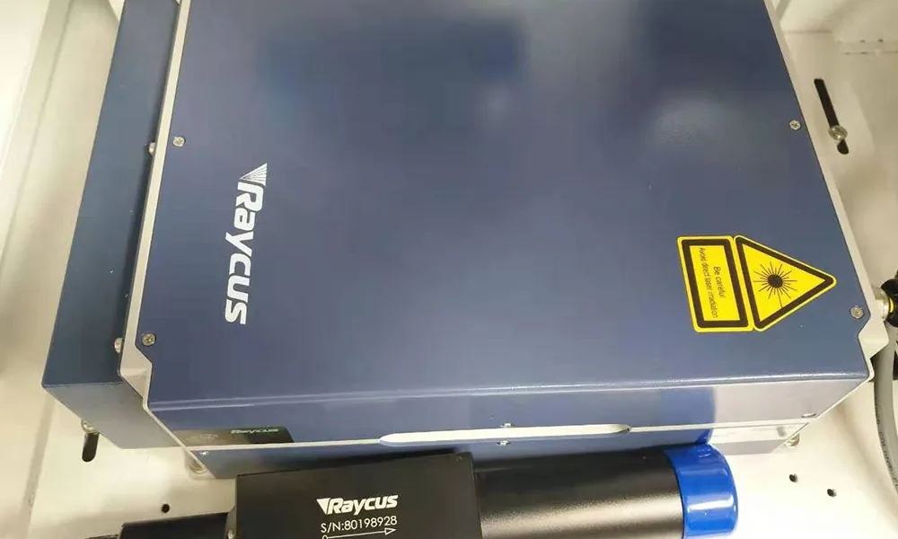
- Laser source: Brand, exact model, rated operating conditions, and supported parameters.
- Marking optics: Galvo scanner, field lens, marking area, and working-distance requirements.
- Cooling: Air- or water-cooled configuration and any supporting equipment required.
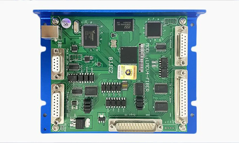
- Controls: Software, controller, variable-data functions, and required interfaces.
- Workpiece handling: Fixtures, positioning aids, and any installed rotary or vision functions.
- Safety and extraction: Actual enclosure, interlocks, and fume-control provisions.
- Delivery scope: Computer, accessories, commissioning, documentation, spare parts, and support terms.
A 5W quotation with a better-matched optical system and more suitable machine configuration may be more valuable than a nominally higher-powered system with the wrong marking field or missing production requirements. A cooling system or optional module should be evaluated as part of the actual equipment package, not assumed to be included because of wattage.
Compare Upgrade Cost Against Accepted Production Output
Power upgrades become easier to justify when they solve a measurable production problem. If a 3W machine produces acceptable marks at the required output rate, a 5W option may not generate enough additional value to justify its cost.
When an acceptable 3W process cannot meet the production target, test whether a 5W configuration improves the completed process sufficiently. A 10W system becomes attractive when the additional output is usable, the material remains within acceptable limits, and the gain matters to production.
Compare accepted parts produced over the required operating period, changes in complete cycle time, rejected marks and rework, recurring operating costs, and any justified need for future capacity. Higher power only adds useful capacity if the process can actually benefit from it.
There is no reliable universal price premium or payback period for moving from 3W to 5W or 10W. Those figures require specific equipment quotations and validated operating data.
How to Compare 3W, 5W, and 10W UV Lasers in a Sample Test
A sample test should answer a purchasing question, not merely demonstrate that a laser can leave a visible mark. The purpose is to determine which proposed configuration meets the same production requirements at an acceptable cost.
Use Representative Workpieces and the Same Acceptance Criteria
Use production-representative samples wherever possible. If the material has multiple grades, finishes, colors, or coatings, include the variations that could change marking behavior.
Each candidate should be evaluated against the same required task: identical marking content and intended dimensions; the same quality and readability criteria; applicable surface-damage limits; production cycle-time requirements; and comparable inspection methods.
For a Data Matrix code, compare whether each candidate produces an acceptable, readable symbol under the intended reader and inspection conditions. A visually darker symbol should not automatically be considered better if its geometry or surrounding material is damaged.
Optimize Each Laser Within Its Supported Process Window
A fair comparison does not necessarily mean forcing every laser to use identical operating settings. Different models may have different rated frequency ranges, pulse characteristics, and output behavior. Applying the same nominal frequency, software power percentage, and scan speed across all machines could unfairly disadvantage one system.
Instead, optimize each candidate within its supported range to meet the same acceptance criteria. Record the installed source model, optics, marking field, focus conditions, pulse frequency, scan speed, hatch spacing, and number of passes where relevant.
If the objective is to isolate laser-source power, control other influential conditions as closely as practical. If the objective is to choose between complete machines, compare their best validated production-ready configurations and document significant hardware differences. A complete-machine comparison can establish which configuration suits the task, but not necessarily that wattage alone caused the result.
Compare Quality, Repeatability, and Complete Cycle Time
Do not base a purchase decision on a single successful mark. Use repeated samples under representative working conditions. Depending on the application, inspect text readability, code verification, contrast, uniformity, surface damage, and any required durability after handling.
| Record item | What to document |
|---|---|
| Workpiece | Material grade, batch, color, coating, thickness, and relevant geometry |
| Marking requirement | Artwork or code, size, location, and acceptance criteria |
| Machine configuration | Source model, optical system, field size, cooling, and relevant installed functions |
| Process settings | Frequency, scan speed, passes, focus, and other relevant parameters |
| Mark quality | Pass/fail outcome, readability, visual defects, and required durability checks |
| Processing time | Laser-only marking time and complete production cycle time |
| Repeatability | Results across repeated samples and relevant production variation |
| Final decision | Whether the configuration meets quality, throughput, and cost requirements |
Compare candidates using accepted output, not the maximum speed at which they can produce any visible mark. If a higher-powered system improves production performance, the gain must still justify the complete-machine configuration and cost.
For further preparation, see the sample marking test checklist.
How to Make the Final 3W, 5W, or 10W Selection
The final decision should follow validated marking requirements rather than a fixed rule that every buyer must progress from 3W to 5W and then to 10W.
- Choose a suitable 3W configuration when it meets the specified quality, cycle time, repeatability, and production-margin requirements. There is no automatic need to upgrade.
- Choose a suitable 5W configuration when testing shows a meaningful improvement in accepted processing efficiency or operating margin that justifies its additional cost.
- Consider a 10W configuration when a verified power-related throughput or processing limitation makes the additional output useful and the marking quality remains acceptable.
- Reconsider the process instead of increasing power when results are limited by material response, focus, optics, positioning, or excessive surface damage.
Some projects justify testing 10W alongside a lower-power candidate from the beginning. The sequence is not mandatory; the acceptance criteria are.
For a useful machine recommendation, prepare representative workpieces or material specifications, marking artwork, marking area, target result, production quantity, and available cycle time. A supplier can then review appropriate source and machine configurations and validate samples before purchase.
Explore the available UV laser marking machines or request an application-based quotation with your marking requirements.
Frequently Asked Questions About 3W, 5W, and 10W UV Lasers
Is a 10W UV Laser Marking Machine Always Water-Cooled?
Do not assume the cooling configuration from wattage alone. Many industrial 10W UV laser sources, including the published JPT SEAL models referenced above, use water cooling, but the required method must be confirmed for the exact source and complete machine. Lower-power UV sources can also be water-cooled, while some 3W and 5W models are air-cooled.
Is UV Laser Output Power the Same as Machine Power Consumption?
No. A 3W, 5W, or 10W rating generally refers to the laser’s optical output power under specified conditions, not complete-machine electricity consumption. Total consumption also depends on the source electronics, power supply, controller, computer, cooling system, and installed equipment. Request the complete machine’s electrical specifications when assessing operating costs or installation requirements.
Can a 3W UV Laser Marking Machine Be Upgraded to 5W or 10W Later?
An upgrade may be possible, but it is not necessarily a simple source replacement. A new laser source must be compatible with the power supply, controller, optical arrangement, cooling, mounting structure, and safety provisions. Recalibration and sample validation may also be needed. If future upgrading matters, ask the supplier whether the proposed platform supports the intended configuration and whether the change would be technically and economically reasonable.