
Dynamic-focus laser marking
3D Laser Marking Machines
3D laser marking machines use dynamic focusing to keep the laser working across controlled changes in height, curvature or marking field. They are used when a normal flat-field setup cannot maintain an acceptable result over curved, stepped, height-varying or selected large-area surfaces.
The correct machine still depends on the material, required marking effect, part geometry, usable X-Y field, Z focus range, workpiece height and production method. Zhuorui can configure and test the machine around the actual part before final selection.
What the machine does
What is a 3D laser marking machine?
A conventional galvo marking system is normally optimized around a flat focal plane. A 3D dynamic-focus system adds controlled focus adjustment while the beam scans in X and Y, allowing the machine to compensate for defined changes in surface height or to work across a larger optical field. The useful result depends on the complete optical system, calibration and actual workpiece geometry—not on the “3D” label alone.
Dynamic focus
The focus position changes together with the X-Y scan so the beam can follow a defined height profile instead of working only on one flat plane.
Curved and stepped surfaces
It is useful when the marking area crosses shallow curves, slopes, steps or other measurable height changes that exceed the tolerance of a normal 2D setup.
Large-field work
Dynamic-focus optics can also support selected large-area marking tasks, but a larger field does not automatically preserve the same spot size, distortion or edge quality everywhere.
Relief workflows
3D focus control can be combined with repeated material removal for relief or depth work, but dynamic focus and deep engraving are different functions and should be evaluated separately.
Buyer decision
Why choose a 3D laser marking machine?
Choose 3D equipment when changing surface height is a real process limitation—not simply because “3D” sounds more advanced. The benefit is greater control over focus across the workpiece; the trade-off is higher optical, software and calibration complexity.
Advantages
Better focus control across height changes. The system can compensate for defined variation in surface height instead of requiring every point to sit on one fixed focal plane.
Fewer mechanical focus adjustments for suitable parts. A known curved or stepped surface can often be processed without repeatedly changing the machine Z height between marking points.
More flexibility for large-field and relief work. Dynamic focus can support larger optical fields and can be combined with multi-pass engraving when the process is validated.
One platform can cover flat and selected 3D work. When the machine configuration and process window allow it, the same system may handle flat parts as well as approved height-varying parts.
Limitations and trade-offs
Higher system cost and calibration complexity. Dynamic-focus heads, software and calibration add cost and require more setup discipline than a basic 2D machine.
Nominal focus range is not the same as usable marking range. Edge quality, spot condition, energy density and distortion still need to be checked on the actual field and height variation.
Dynamic focus does not create beam access. Hidden faces, severe wrap-around geometry or near-vertical surfaces may still require rotary motion, repositioning or multi-axis engineering.
Material response still controls the laser-source choice. 3D geometry does not make the wrong wavelength or pulse behavior suitable for the material.
Do not mix the concepts
2D laser marking vs 3D dynamic focus vs deep engraving
These terms describe different parts of the process. 2D and 3D mainly describe how focus is managed across the marking surface. Deep engraving describes material removal depth and normally requires repeated passes, suitable pulse conditions and sufficient process time.
| Comparison | 2D Laser Marking | 3D Dynamic Focus | Deep Engraving |
|---|---|---|---|
| Main purpose | Mark a flat or nearly flat surface around one focal plane | Maintain focus across a controlled height change, curvature or selected large field | Remove material to create measurable depth or relief |
| Focus control | Primarily fixed focal plane | Focus changes dynamically with X-Y scanning | May use 2D or 3D focus control depending on geometry |
| Best starting geometry | Flat, repeatable parts | Curved, stepped or height-varying surfaces within a usable envelope | Any suitable surface where controlled material removal is required |
| Does it automatically create depth? | No | No | Yes, depth is the process objective |
| Typical selection question | Can the whole mark stay within acceptable focus tolerance? | Can the full surface stay inside the calibrated and usable 3D envelope? | Can the material, source, pulse strategy and cycle produce the required depth and finish? |
Available laser-source routes
Choose the 3D machine from the material and marking result
The 3D function solves focus variation; it does not replace laser-source selection. Start with the material and required mark, then match the source to a compatible dynamic-focus head, optics, field, software and complete machine structure.
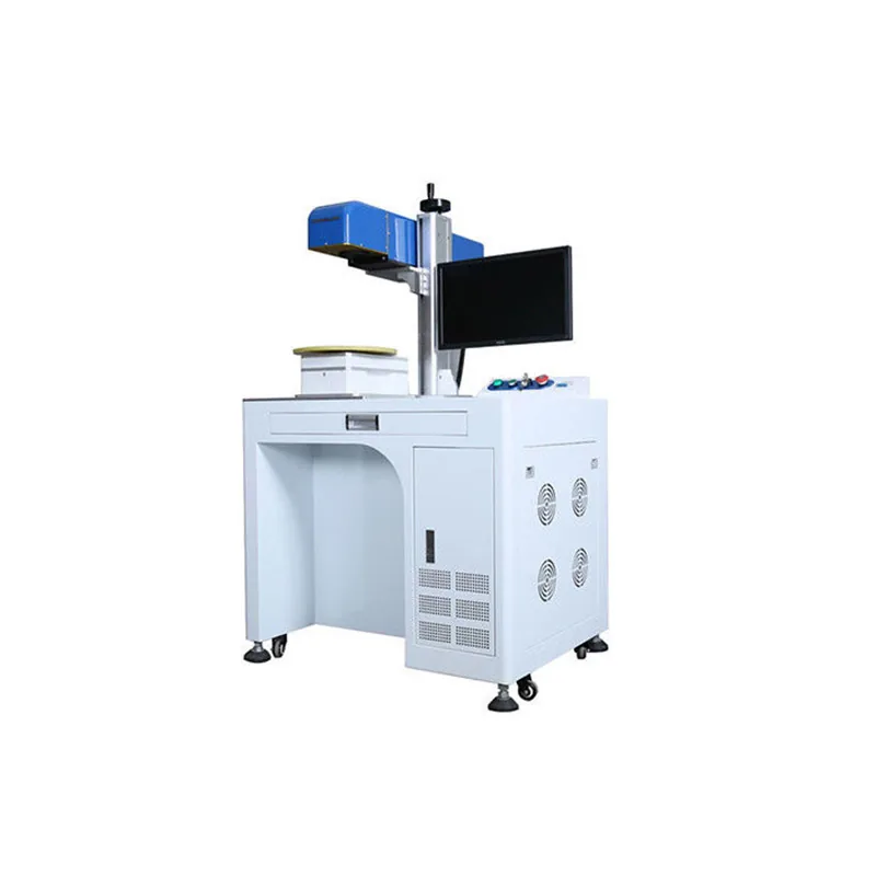
Main 3D route for metals
3D Fiber Laser Marking Machine
Fiber is the main starting route for metals and compatible coated or treated surfaces. Depending on the source and pulse behavior, it can be used for contrast marking, coating removal, engraving and selected relief work.
- Best starting point: metals and many metal-surface marking tasks.
- Confirm: source type, pulse behavior, field size, Z focus range, part geometry and required result.
- Do not choose only by average laser power; spot condition, pulse characteristics and process strategy also matter.
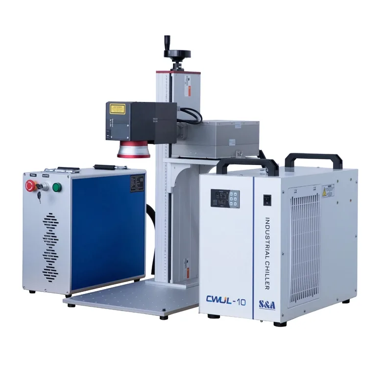
Conditional 3D route
3D UV Laser Marking Configuration
UV can be evaluated when the material or target effect favors a shorter wavelength and lower heat input than a typical fiber route, while the surface geometry still requires dynamic focus.
- Starting applications: selected plastics, coatings, glass-related materials and heat-sensitive surfaces.
- Confirm: exact material construction, desired contrast or removal, cooling, supported head/source combination and sample result.
- UV does not mean “no heat”; the material and process window still need testing.
Other source combinations: Do not select a 3D machine from the source name alone. If your application requires another wavelength or a non-standard optical package, send the material and workpiece first so the complete source/head/optics combination can be evaluated before quotation.
Dynamic-focus system
What changes inside a 3D marking machine
A 3D machine is not just a standard galvo machine with different software. The dynamic-focus head, optics, calibration, controller and machine structure must work as one system.
Dynamic-focus head
Controls the additional focus axis while X and Y scan the marking pattern. Head aperture, supported wavelength and optical design influence the usable field and focus change.
Optics and field
Field size, working distance, scan angle and spot condition are linked. A larger field can reduce energy density or edge performance, so the usable result must be checked rather than inferred from a nominal field value.
Software and calibration
The controller must coordinate scan position with focus position. Calibration connects the commanded geometry to the actual machine and should be checked across the part area that matters to production.
Machine structure
The column, worktable, Z adjustment, fixture interface, cooling, extraction and guarding determine whether the optical package can be installed and used repeatably on the real workpiece.
Size confirmation
How to confirm the 3D working envelope
For a 3D machine, “marking area” is not enough. The quotation should define the X-Y marking field together with the usable Z focus change, workpiece height, working distance and actual geometry. These values are related and should be checked as one package.
| Item | What it means | Why it matters | What to provide |
|---|---|---|---|
| X × Y marking field | The nominal horizontal scan area | Defines the overall mark size, but edge quality and spot condition may change as the field grows | Actual mark dimensions and position on the part |
| Usable Z focus range | The height variation the dynamic-focus system can compensate within the selected optical setup | Determines whether the highest and lowest marking points stay inside a usable process window | Total height difference across the marking surface |
| Working distance | The optical distance between the marking head and the workpiece region | Affects machine clearance, fixture design and whether the part can physically sit in the correct position | Part dimensions, fixture height and loading method |
| Maximum part height / machine clearance | The physical space available under the marking head | A part can fit the optical range but still be too tall for the machine body or fixture arrangement | Overall part and fixture dimensions |
| Curvature and slope | The change in surface normal and height across the mark | Dynamic focus changes focal position, but it does not make hidden or severely angled faces optically visible | Drawing, CAD model or clear side-view dimensions |
| Center-to-edge result | The mark quality across the complete required field | Confirms that the actual field—not only the center—meets the required appearance, feature size or readability | Acceptance points and pass/fail criteria |
Do not use a single generic X-Y-Z number as a universal machine specification. The usable combination depends on the selected dynamic-focus head, optics, source, field and required marking result. Final values should be confirmed for the quoted configuration.
Machine configuration
Configure the complete machine around the workpiece
Once the source and 3D optical package are selected, the machine body and production accessories must support part loading, focus position, repeatable locating, extraction and the required production cycle.
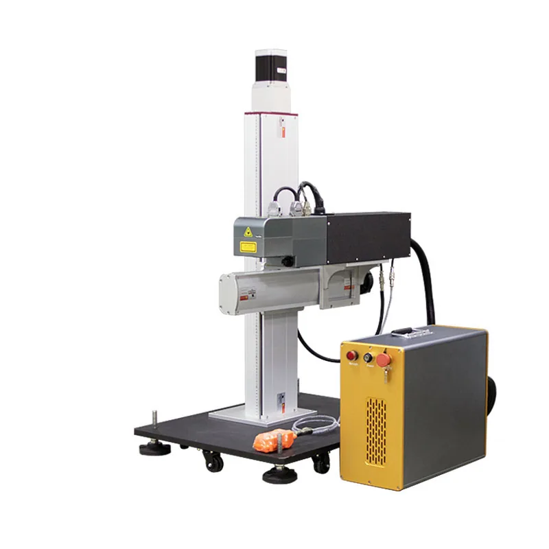
Complete-machine configuration
Machine Body & Worktable
Confirm the column, Z adjustment, worktable size, available clearance and loading method around the real part. The machine structure must physically support the required working distance and fixture height.
Workholding
Fixture & Positioning
Fixtures are used when the part needs a repeatable datum or when different batches must return to the same position. The fixture should locate the part without blocking the required beam path.
- Standard worktable locating
- Custom fixture or nest
- Repeatable datum for sample and production checks
Optional motion
Rotary, XY or Other Motion
Dynamic focus controls focal position; it does not rotate the part or expose hidden faces. Rotary or multi-position motion can be evaluated when the required mark extends beyond the optically visible surface.
- Rotary evaluation for cylindrical work
- XY or repositioning for larger coverage
- Project review for multi-face or automated movement
Typical workpieces
Where 3D laser marking is useful
3D dynamic focus is most valuable when surface geometry is the reason a normal flat-field process becomes unstable or inefficient. The final source and parameters still depend on the actual material and required mark.
Molds, tools and formed metal parts
Useful where the mark crosses shallow 3D features, sloped faces or controlled height variation on metal components. The main benefit is that one marking program can follow these height changes without repeatedly repositioning the part or mechanically resetting the Z height between marking zones.
Curved or stepped components
Suitable when the marking surface moves above and below one normal focal plane but remains optically visible to the marking head. 3D dynamic focus is valuable here because it can compensate for controlled surface-height changes that would otherwise push part of the mark outside the usable focus tolerance of a conventional 2D setup.
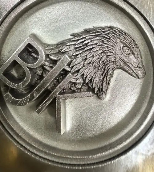
Relief and depth engraving
Dynamic focus can support controlled multi-pass removal on 3D geometry when the selected source, process strategy and cycle are suitable. Its value is the ability to adjust focus as the engraved surface level changes, helping maintain a usable process condition through successive depth levels rather than relying on one fixed focal plane.
Selected large-area marking
Dynamic-focus optics can be evaluated when the required field is larger than a conventional flat-field setup, with center-to-edge quality confirmed by testing. The reason to use a 3D optical route is not field size alone, but the ability to control focus across a wider scan area where a normal flat-field configuration may no longer keep the required spot condition and result consistently usable.
Know the boundary
When 3D dynamic focus is not enough
Dynamic focus changes focal position. It does not automatically solve beam access, hidden faces, severe wrap-around geometry, custom workholding, part motion or production-line integration.
A standard 3D machine is a good starting point when
The complete marking area is visible from the marking head, the surface height change can be described, the part fits the available machine clearance, and the required result can be validated within the selected X-Y-Z working envelope.
Move to a custom 3D solution review when
The mark wraps around a cylinder or cone, crosses hidden or steep faces, needs a rotary axis or XY motion, requires special fixturing, uses surface mapping or CAD compensation, or must integrate with a larger automation process.
For these workpieces, use the 3D curved-surface solution review so the geometry, fixture, motion, file preparation and acceptance method can be evaluated together.
Sample validation
How to validate a 3D marking result before release
For 3D work, one attractive sample at the center of the field is not enough. The useful test should represent the actual material, geometry and marking positions that matter in production.
Review the actual workpiece
Confirm the material, coating, overall dimensions, marking area, highest and lowest marking points, curvature, fixture datum and beam access. A drawing or CAD model is useful when the surface cannot be described reliably with simple dimensions.
Match the complete machine configuration
Confirm the laser source, dynamic-focus head, optics, field, working distance, machine clearance, software, cooling and fixture as one configuration. Do not treat the dynamic-focus head as an isolated specification.
Test center, edge, high and low points
Use representative positions across the actual marking surface. Compare the center and field edges, plus the highest and lowest areas of the workpiece, so focus compensation and field consistency are tested where failure is most likely.
Define the acceptance criteria
Depending on the task, inspect mark position, contrast or removal, depth or texture, smallest feature, distortion, edge-to-center consistency, code readability, heat or coating damage and repeatability across representative parts.
Machine supply
What to confirm in the delivered 3D machine
Zhuorui assembles, configures, debugs and tests the complete laser marking machine. The final quotation should identify the machine structure and the configuration that was selected for your workpiece rather than leaving the key optical and mechanical items ambiguous.
Core marking system
- Laser-source route
- Dynamic-focus head and compatible optics
- Controller and supported software
- Quoted X-Y field and confirmed 3D working range
Machine structure
- Column, Z adjustment and worktable
- Fixture or locating interface where required
- Cooling and electrical configuration
- Extraction and guarding requirements for the installed system
Application validation
- Representative material and geometry
- Sample-marking review
- Center/edge/height comparison where relevant
- Agreed acceptance criteria
Custom options
- Rotary or special fixture evaluation
- Alternative machine structure where required
- Motion or integration review for project applications
- OEM or configuration changes subject to project review
Buyer questions
3D laser marking machine FAQ
What is the difference between 2D and 3D laser marking?
A conventional 2D galvo system is normally optimized around one focal plane. A 3D dynamic-focus system adds controlled focus adjustment during X-Y scanning so it can compensate for a defined change in surface height or support selected large-field work.
Does 3D laser marking mean deep engraving?
No. 3D dynamic focus describes how the beam is focused across geometry or field. Deep engraving describes material removal over repeated passes. They can be combined, but they are not the same function.
Is a 2.5D laser engraving machine the same as a 3D dynamic-focus machine?
Not necessarily. “2.5D” is used differently by different suppliers and may describe layered, grayscale or multi-depth engraving without continuous dynamic focus across a curved surface. When comparing machines, check whether the system actually controls focus dynamically during X-Y scanning and what calibrated X-Y-Z working envelope the quoted configuration supports instead of relying on the 2.5D or 3D label alone.
Should I choose a 3D fiber or 3D UV machine?
Choose the laser source from the actual material, surface and target effect first. Then confirm that the selected dynamic-focus head, optics, software and cooling support that source and the required geometry.
Can a 3D machine mark flat parts?
Yes, if the selected machine and process are suitable for the flat task. However, if all parts are flat and stay inside the focus tolerance of a normal 2D setup, a 3D machine may add unnecessary cost and complexity.
How do I know whether my curved part fits the 3D range?
Provide the X-Y mark size, total height variation, overall part height, curvature or slope, fixture height and drawing or CAD data when available. The usable range should then be checked against the selected optical system and required marking result.
Can 3D dynamic focus mark around a complete cylinder?
Not by focus adjustment alone. A complete wrap-around mark normally needs part rotation or another motion strategy because surfaces outside the optical line of sight cannot be reached simply by changing focus.
What should be tested before purchasing?
Test the actual or representative material and geometry. Check the center and field edges, high and low points, mark appearance, position, distortion, fine features or code readability, thermal or coating damage and repeatability against agreed acceptance criteria.
Quote-ready inputs
What to send for a 3D laser marking machine quotation
The fastest way to select the machine is to start from the real part. Send enough information to confirm the source route, 3D working envelope, machine clearance, fixture and acceptance method before the configuration is finalized.
Part & material
- Material, grade, color, coating and surface treatment
- Overall part dimensions and representative sample
- Drawing or CAD model when available
- Curvature, slopes, steps and total height variation
Mark requirement
- Artwork, text, logo or code file
- Physical mark size and position
- Required contrast, removal, texture, depth or fineness
- Position, distortion or readability requirement
Production
- Parts per batch and target cycle
- Manual or automatic loading
- Fixture and changeover requirements
- Variable data, trigger or integration needs
Acceptance
- Critical center, edge, high and low test points
- Pass/fail criteria
- Inspection or measurement method
- Required sample quantity before order confirmation
Send the workpiece information first. Zhuorui can then determine whether the job fits a standard 3D machine configuration or should move to a curved-surface, rotary or motion-based project review.
Request a QuoteSend the part before selecting the 3D machine
Share the material, drawing or CAD file, marking area, height variation, target result, production cycle and acceptance method. Zhuorui can review the laser-source route, 3D working envelope and complete machine configuration around the actual application.