
Laser Machine Accessories
Laser Marking Machine Accessories
Choose between two distinct accessory families: functional attachments added to expand how the laser marking machine handles a job, and machine components that form or service the machine itself. Then confirm compatibility with the actual machine, source, optics, controls and safety boundary.
Start with the production problem
What Are You Trying to Change?
Start with the job that is not working today. The likely accessory family becomes much easier to narrow once you define whether the problem is part handling, positioning, field coverage, component replacement, extraction or production flow.
Mark around a cylinder
Start with: rotary axis or roller rotary. Confirm part diameter, length, weight, clamping method, runout and controller support.
Reach a larger work area
Start with: XY motion, indexing or a different field lens depending on whether the need is physical travel or optical field. Confirm travel, datum, field size and working distance.
Reduce loading variation
Start with: fixture, nest or vision assistance. Confirm the part datum, repeatability, visible locating features, height variation and mark access.
Mark on a moving line
Start with: conveyor, flying kit, encoder, trigger and control I/O. Confirm line speed, trigger timing, data flow and stop/restart behavior.
Replace or change the marking field
Start with: F-theta lens or related optics. Confirm wavelength, coating range, aperture, focal length, thread, field and working distance.
Replace a failed machine component
Start with: laser source, galvo, control card, power supply or cooling component. Match the actual model, interfaces, software, electrical requirements and cooling method.
Improve fume control or guarding
Start with: extraction or enclosure accessories. Confirm process fumes, capture point, airflow path, door/interlock requirements and service access.
Increase repeatability between products
Start with: dedicated fixtures, adjustable holders, indexing or vision. Confirm changeover method, product variation, datum control and the acceptance requirement.
Two clear entry points
Choose the route that matches the job
Use the functional-accessory route when you need the machine to handle, position, move, feed, inspect or protect the job differently. Use the machine-component route when you are replacing or configuring the optical, control, power or cooling hardware inside the machine. Specific models should only be chosen after the machine and task conditions are matched.
Make the workstation perform the task
Functional Accessories & Attachments
Rotary axes, XY tables, electric Z axes, conveyor and flying kits, vision kits, fixtures, fume extractors, safety enclosures and trigger devices. Use this route when the question is about part handling, positioning, access, extraction or operator interaction.
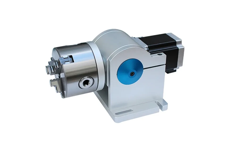
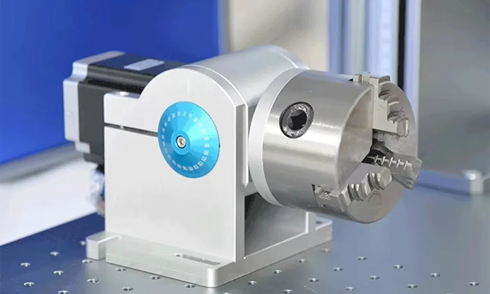
Example shown: D80 rotary axis. Final chuck range, load, motor, mounting and controller compatibility must be confirmed for the actual machine.
Explore Functional Accessories & Attachments >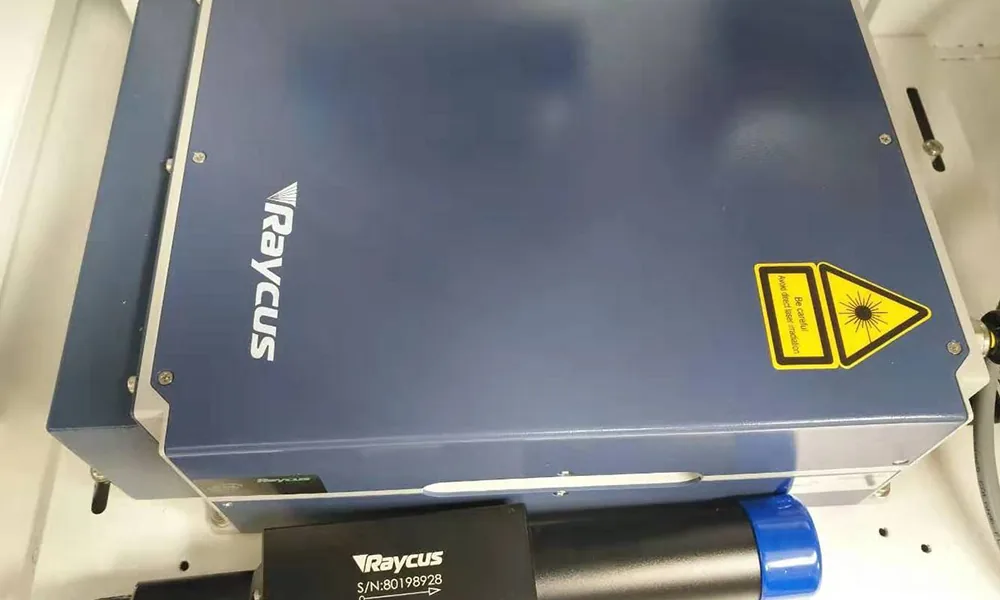
Keep the machine supplied and serviceable
Machine Components & Replacement Parts
Laser sources, galvo scanners, F-theta lenses, control cards, power supplies, water chillers, industrial computers, protective optics and 3D dynamic-focus heads. Use this route when the question is about machine architecture, a sourced component or a service replacement.
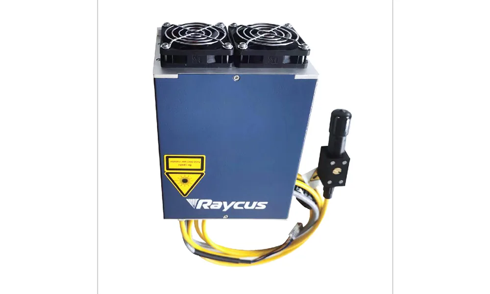
Example shown: installed Raycus source. Brand, exact model, wavelength, rated power, electrical interface and cooling requirements must match the machine being serviced.
Explore Machine Components & Replacement Parts >Compatibility and selection
Machine and Workpiece Conditions Change the Accessory Choice
The same accessory name can lead to different hardware once the real machine, workpiece and production method are considered. Use the conditions below to understand what actually changes the selection.
- Diameter and geometry: changes whether a chuck rotary, roller rotary, fixture, flat table or multi-position setup is practical, and whether the mark area remains accessible.
- Weight and inertia: affect rotary torque, table load, acceleration and stopping behavior; an attachment that physically fits can still be mechanically unsuitable.
- Part height and surface position: change Z travel, working distance, enclosure clearance and whether the focused field can reach the required surface.
- Part-to-part variation: determines whether a fixed fixture is enough or whether vision, adjustable workholding or a different datum strategy is needed.
- Production flow: manual loading, batch fixtures, indexing tables and continuous conveyors require different motion, trigger, I/O and safety arrangements.
- Machine architecture: controller, connector, mounting pattern, source type, wavelength, optical aperture, software and cooling determine whether the accessory or replacement can actually integrate with the machine.
Category 01 – Added capabilities
Functional Accessories & Attachments
These are external modules added to a laser marking machine to expand how it positions, holds, moves, feeds or protects the work. They are not the machine’s internal optical or electrical components.
Open the Functional Accessories category >- Positioning and motionRotary axes, XY moving tables, electric Z axes and indexing turntables.
- WorkholdingFixtures, jigs, clamps, nests and product-specific holders.
- Line extensionsConveyor/flying kits, vision kits, sensors and trigger devices.
- Operator and safety supportFume extractors, safety enclosures and related workstation attachments.
Rotary axes
Chuck and roller configurations for rings, tubes and cylindrical workpieces; confirm diameter, load, runout, motor and controller compatibility.
XY moving tables
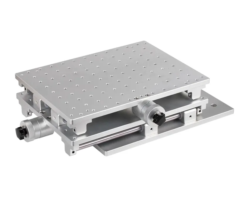
Manual or powered X/Y motion for part positioning and larger work areas; confirm travel, repeatability, load and mounting pattern.
Fixtures & holders
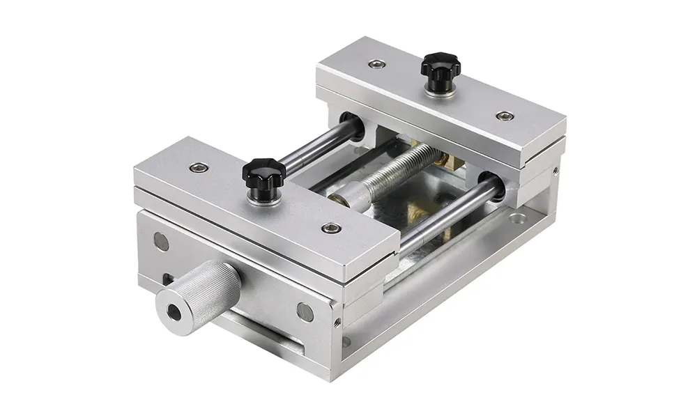
Adjustable workholding for cards, sheets and small parts; confirm datum, clamping range, surface protection and mark access.
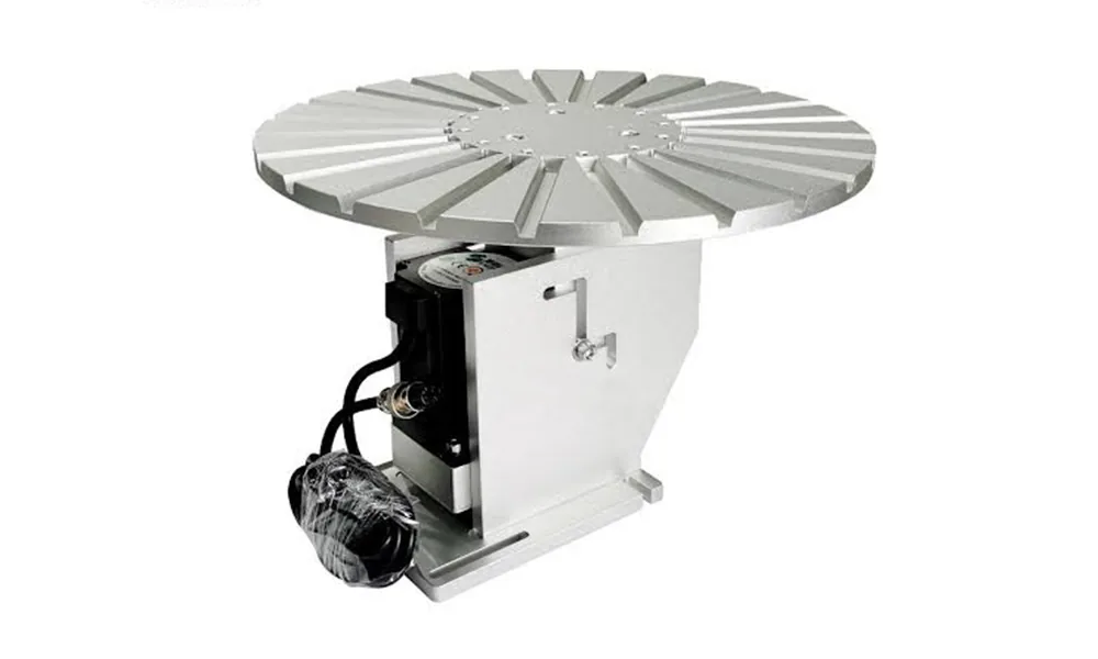
Rotary & indexing tables
Large rotary or indexing worktables for repeated presentation; final station sequence, guarding and cycle performance belong to the solution review.
Visual examples
Representative Functional Accessories
These examples show different ways accessories can hold or rotate a workpiece. Use the images to identify the attachment type; final load, motion range, mounting and controller compatibility still need to be checked against the actual machine.
Category 02 – Machine hardware
Machine Components & Replacement Parts
These are optical, scanning, control, power and cooling components that form or service the laser marking machine itself. They are selected by the machine BOM and interfaces, not by the workpiece-handling task.
Open the Machine Components category >- Laser and beam deliveryLaser sources, galvo scanners, scan heads, F-theta lenses and protective optics.
- Control and electricalControl cards, power supplies, industrial computers, displays, cables and I/O hardware.
- Cooling and serviceWater chillers, fans, filters and model-specific replacement parts.
- Advanced optical modules3D dynamic-focus heads and optical assemblies that must be confirmed against the source and machine.
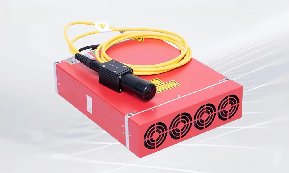
Laser sources
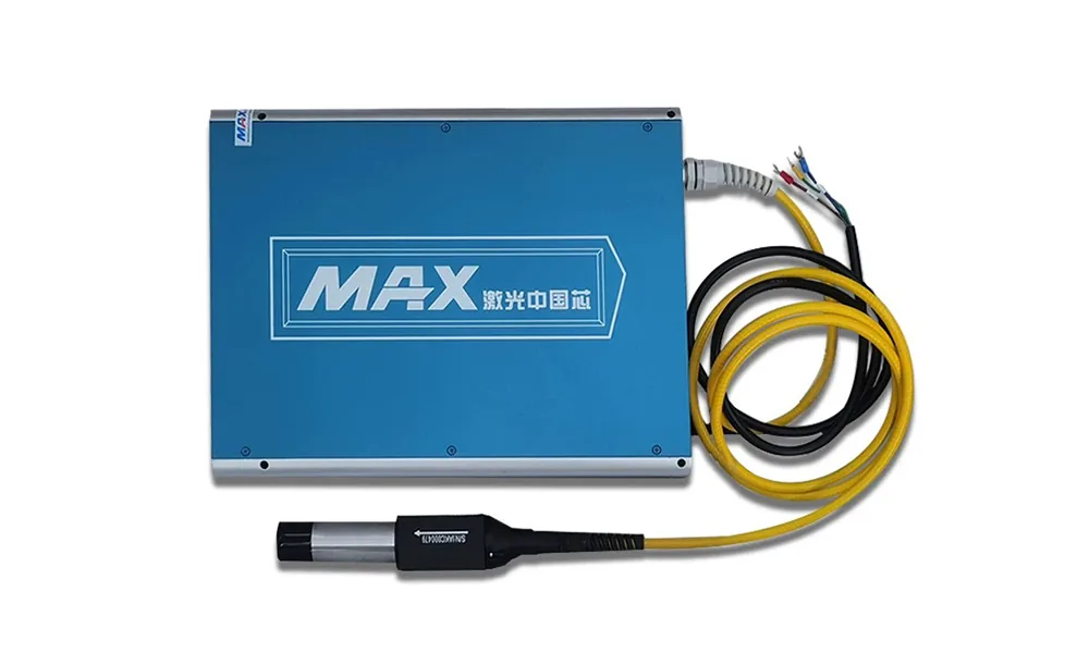
Source brands and models for service or configuration must match the source family, rated power, pulse behavior, cooling and electrical interface.
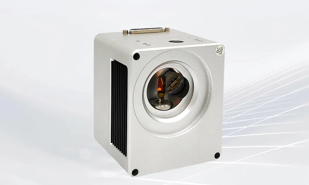
Galvo & scan heads
Scanning assemblies must match aperture, wavelength, controller, lens and the validated machine configuration.
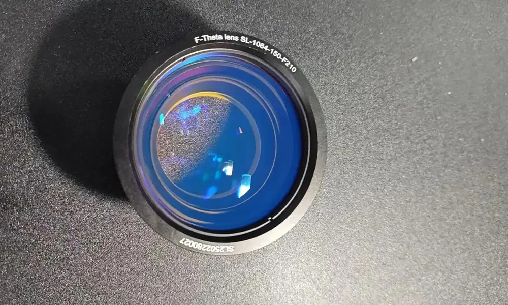
F-theta lenses
Field lenses and protective optics matched by wavelength, coating, focal length, field, working distance, aperture and thread.
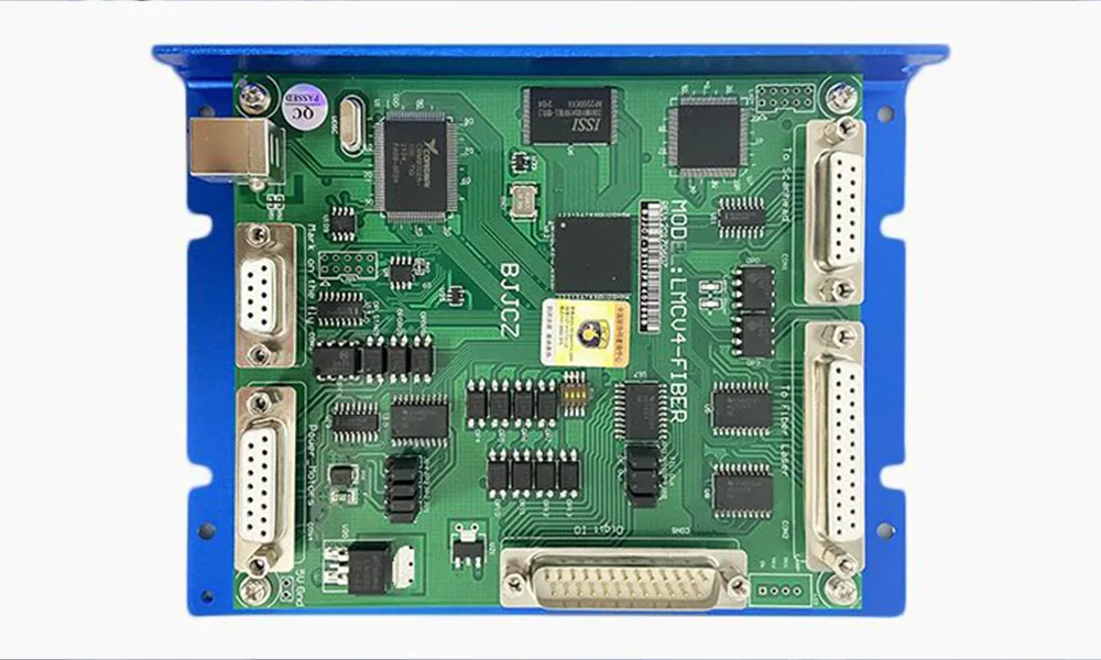
Control cards
Marking controllers and interface boards require matching software, connector layout, supported functions, driver and machine wiring.
Visual examples
Representative Machine Components
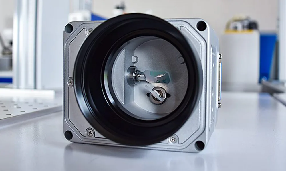
Laser sources, scan heads, lenses and control hardware are selected by the complete machine configuration. The source images below are third-party component examples; the visible brand or appearance alone does not establish interchangeability.
Capability boundary
What Accessories Can Change — and What They Cannot
Accessories can extend how a marking machine holds, moves, sees, feeds, focuses or protects a job. They do not automatically correct a fundamentally wrong laser source, material route or production concept.
Motion and workholding can change
Rotary axes, XY tables, fixtures and indexing systems can change how the workpiece is presented to the laser.
They can improve access, positioning and repeatability, but they do not guarantee focus on every curved surface or compensate for an unstable part datum.
Optics and machine components can change
Lenses, galvos, sources and controllers can change the optical field or restore/configure machine hardware.
A larger marking field is not automatically more precise, and a similar-looking component is not automatically interchangeable. Wavelength, aperture, working distance, software and interfaces still matter.
Vision and automation have limits
Vision can help identify position and orientation; conveyors, triggers and I/O can connect the marking station to production flow.
They do not automatically solve height variation, poor focus, unstable features, unsuitable material response or an undefined acceptance criterion.
Material response still has to be proven
An accessory changes the machine setup, not the fundamental laser-material interaction.
If the core problem is contrast, heat damage, depth, durability or code quality, the laser route and real sample still need to be evaluated separately.
Selection risks and failure modes
Common Ways an Accessory Choice Fails
Most accessory problems appear at the mechanical, optical, control or safety interface rather than in the accessory name itself. Check these failure modes before ordering or modifying the machine.
Matching by name instead of interface
A “rotary axis,” “110 x 110 lens” or similar galvo can still be wrong because the connector, mounting pattern, controller, wavelength, aperture, driver or working distance is different.
The workpiece fits, but the motion does not
A chuck can hold the part while still exceeding load, runout, clearance or torque limits. A fixture can locate the part but block the marking area or make loading inconsistent.
Optical changes create a new trade-off
Changing a lens, galvo or beam-delivery component can alter field size, working distance, focus behavior or optical compatibility. A larger field does not automatically improve precision or marking quality.
Vision or automation is expected to solve the wrong variable
Vision can correct XY position or orientation only when usable features are visible and calibration is stable. It does not automatically correct height variation, poor focus, unsuitable materials or an undefined process window.
The accessory changes the safety boundary
Rotary devices, fixtures and moving parts can change reflection angles, guarding needs and operator access. Review enclosure, interlocks, emergency stop, safe motion and service access for the completed configuration.
Extraction, cooling or abnormal-stop behavior is overlooked
Fumes, coatings, added heat load, powered axes and conveyors can introduce new extraction, cooling and restart requirements. Define fault response and safe recovery before production use.
Before ordering or replacing
Validate the Accessory on the Real Machine
A correct-looking component can still fail at the connector, field, software, cooling, motion or safety interface. Final selection should be based on the actual machine and production condition, not only a catalog description.
Identify
Record the machine model, source, controller, serial or current component label, plus the production task the accessory must support.
Match
Compare mounting, connector, optical range, working distance, travel, load, software, power, cooling and any controller or I/O requirement.
Test
For attachments, verify fit, clearance, motion, repeatability and access on the real workpiece. For optical or electrical parts, verify focus, field, marking behavior, communication, thermal behavior and stable operation as applicable.
Confirm the order
Before release, confirm the exact model or part number, included brackets/cables, controller or software requirements, installation/calibration work, known limits and any remaining test requirement.
FAQ
Common accessory questions
How do I know whether an accessory fits my machine?
Provide the complete machine model, source and wavelength, controller, mounting/interface details, part geometry and intended task. Compatibility should be checked against drawings, supplier data, measured interfaces and the real installation condition where relevant.
Does changing an F-theta lens only change the marking area?
No. Lens selection can also change focal length, working distance, spot behavior, usable aperture and the relationship with the galvo and source wavelength. A larger field is therefore not a simple drop-in upgrade in every machine.
Will adding a rotary, vision system or conveyor require software or controller changes?
It can. The answer depends on the existing controller, available I/O, drivers, trigger method and motion functions. Confirm the control architecture before treating a mechanical attachment as plug-and-play.
Are sourced galvos, lenses or laser sources manufactured by Zhuorui?
Not necessarily. A component may be supplied under a third-party brand or manufacturer model that must be confirmed for the actual machine. Zhuorui integration or support should not be interpreted as manufacture of the core component.
What should I send for a replacement review?
Send the machine model, component label or photo, serial/revision, connector and mounting details, failure symptom, production impact and any original drawing or supplier reference.
Next step
Send the machine and task details before you choose a component
Include the machine model, serial or current component label, source and wavelength, controller, part geometry, expected load or speed, interface photos, mark requirement and any safety or extraction constraint. The review should identify the appropriate accessory or component route, the compatibility basis, any additional hardware or machine changes required, the remaining test items and the information needed to finalize the exact model and quotation.