
Laser Marking Materials
Laser Marking Materials: Start with the Exact Material and Surface
Use this laser marking materials hub to identify the right material family, narrow the likely laser route, and understand what must be confirmed before machine selection. The exact grade or formulation, surface condition, coating, color, geometry, target mark, and representative sample test can all change the final recommendation.
Quick Answer
A Material Name Is Only the First Screening Input
Alloy grade, polymer formulation, coating, color, finish, thickness, cleanliness, and post-process requirements can change absorption, heat flow, contrast, marking speed, and surface damage risk.
Start with the real substrate and surface. “Stainless steel,” “aluminum,” or “plastic” is only a category. Alloy or resin grade, pigment, filler, anodizing, plating, paint, coating, roughness, and cleanliness can change how the laser interacts with the part.
Then define the result you actually need. A readable code, cosmetic contrast, black mark, coating removal, annealed mark, or engraved depth can require different laser and parameter directions even on the same base material.
Material Routes
Choose a Material Family
Choose the family that best matches the actual substrate or surface system. The material-specific pages go deeper into response behavior, likely laser routes, process risks, and what should be confirmed by sample testing.

Representative uploaded metal sample.
Metals
Compare metal grades, surface states, reflection, heat flow, annealing, ablation, black marking, and engraving risks before choosing a fiber or MOPA direction.
Explore metals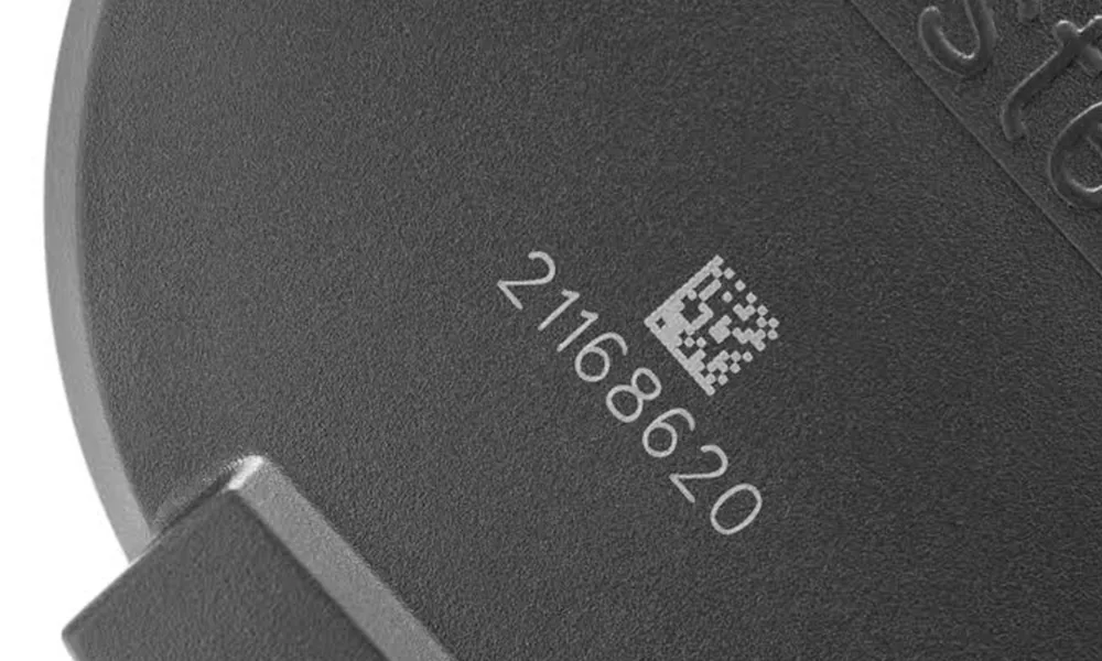
Representative uploaded plastic sample.
Plastics & Polymers
Review resin family, pigments, fillers, flame retardants, additives, molded color, melting risk, contrast behavior, and fume controls using final molded parts.
Explore plastics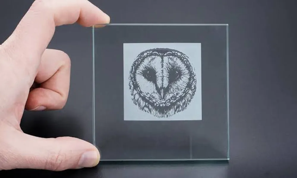
Representative uploaded acrylic sample.
Glass, Crystal & Ceramics
Control absorption, focus, residual stress, glaze, crack risk, surface frosting, and sub-surface effects for brittle transparent and technical materials.
Explore glass and ceramics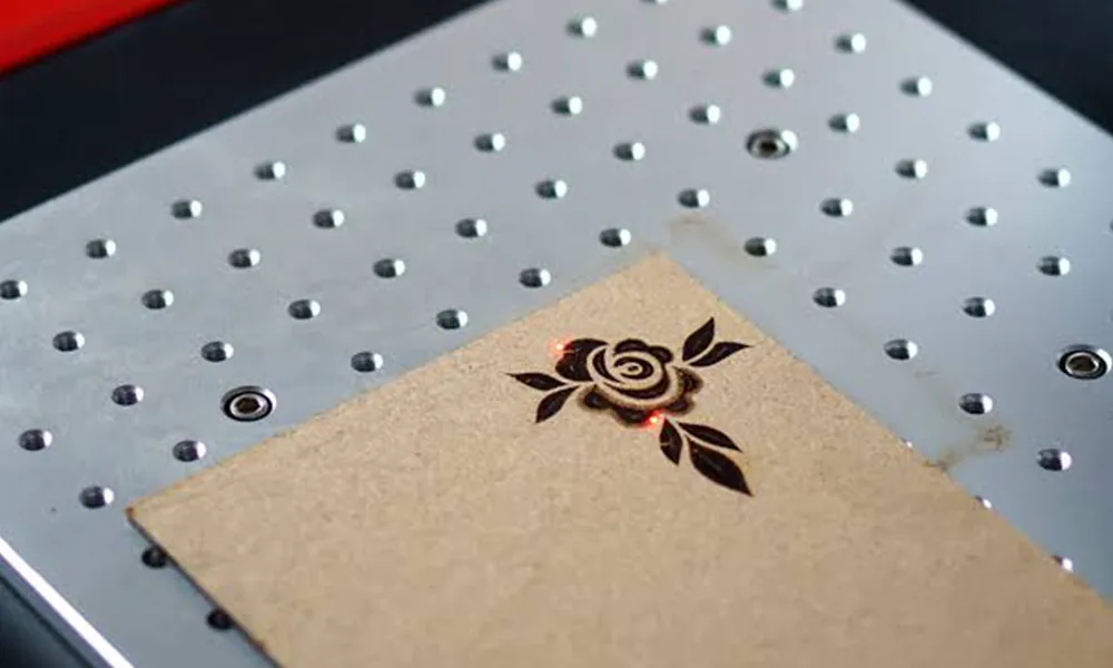
Representative uploaded wood sample.
Wood, Leather, Paper & Textiles
Evaluate organic composition, finish, charring, melting, smoke, fire control, and production handling for natural and flexible materials.
Explore organic materials
Representative PCB substrate image; verify final layer stack and solder mask before approval.
Electronic Substrates
Define heat, particle, code-size, layer-stack, and circuit-clearance limits for PCBs, wafers, ceramic substrates, solder mask, and display materials.
Explore electronic substrates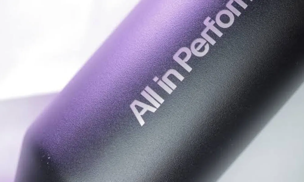
Representative uploaded aluminum surface sample.
Coatings & Surface Treatments
Treat paint, anodizing, plating, oxide layers, powder coating, and coated plastics as layered systems with functional boundaries.
Explore coatings
Representative uploaded copper sample; not a universal special-material proof.
Stone, Composites & Special Materials
Use sample-led qualification for mineral, fiber-reinforced, foam, rubberized, and other special materials where dust, fumes, and thermal effects may dominate.
Explore special materialsMaterial Screening Matrix
Use the Material Family to Choose a Starting Evaluation Route
The table below is a first-pass engineering screen, not a fixed machine prescription. Exact grades, formulations, coatings, target effects, geometry, and acceptance criteria can change the suitable laser route, so representative sample testing remains the final validation step.
| Material or surface family | Common starting direction | What can change the answer | Best next step |
|---|---|---|---|
| Steel & stainless steel | Fiber or MOPA fiber is a common starting route for contrast, annealing, black marking, ablation, or engraving evaluation. | Alloy grade, surface finish, heat sensitivity, required color/blackness, depth, corrosion exposure, and post-processing. | Review Metals and validate the required mark on the final surface. |
| Aluminum, anodized aluminum & plated metals | Fiber or MOPA fiber is often the first route to evaluate; coated or anodized surfaces must be treated as layered systems. | Alloy, anodizing or plating layer, color, coating thickness, desired contrast, and whether the substrate may be exposed. | Review Metals and Coatings. |
| Copper & brass | Fiber or MOPA fiber can be evaluated, but reflective and thermally conductive surfaces usually require sample-led tuning. | Alloy, polish, plating, oxide state, target contrast or depth, heat input, and surface-quality limits. | Start with Metals and confirm the final alloy and finish. |
| Plastics & polymers | Fiber, UV, or CO2 may be appropriate depending on the polymer formulation, additives, color, and required mark mechanism. | Resin family, pigment, fillers, flame retardants, laser additives, molded color, melting risk, and cosmetic limits. | Review Plastics & Polymers using the final molded part. |
| Glass, crystal & ceramics | UV or CO2 may be evaluated depending on the exact material and target effect; brittle and transparent parts require cautious testing. | Transparency, glaze, residual stress, thickness, surface condition, crack risk, and whether frosting or another effect is required. | Review Glass & Ceramics and test representative parts. |
| Wood, leather, paper & textiles | CO2 is a common starting route for many organic materials, but the final result depends strongly on composition and finish. | Density, moisture, coating or finish, color, charring, melting, smoke, fire risk, and handling requirements. | Review Organic Materials. |
| Electronic substrates | UV, fiber, or CO2 can be considered depending on the layer stack, feature size, thermal budget, and the layer being marked or removed. | Solder mask, copper, ceramic, polymer layers, clearance to circuits, particle limits, code size, and heat sensitivity. | Review Electronic Substrates. |
| Paint, anodizing, plating & other coatings | The laser route depends on both the coating and the base substrate, especially when the target is coating removal rather than bulk-material marking. | Layer material, thickness, adhesion, base material, no-damage boundary, contrast target, and downstream corrosion or cosmetic requirements. | Review Coatings & Surface Treatments. |
| Stone, composites & special materials | No single route should be assumed. Start with the material constituents, target effect, and a controlled sample test. | Binders, fibers, fillers, foams, dust, fumes, thermal damage, delamination, surface texture, and unknown additives. | Review Special Materials and use sample-led qualification. |
About “verified” materials: this hub does not label a material as universally verified from its name alone. A Zhuorui sample result can support a specific material, surface, machine route, and target effect, but production approval should still use the customer’s representative part and agreed acceptance criteria.
Engineering Decisions
What Determines Material Compatibility
The same material family can require different equipment, parameters, and acceptance checks when the surface, result, or production method changes.
Material Identity
Record alloy, resin, glass type, ceramic type, filler, pigment, supplier, and batch where available. Commercial names can hide different formulations.
Surface Stack
Coating, plating, anodizing, paint, oxide, roughness, cleaning state, and post-treatment can change the actual laser interaction more than the base material name.
Mark Mechanism
Annealing, color change, foaming, frosting, carbonization, ablation, coating removal, and engraving use different process windows.
Geometry and Heat
Curved parts, thin walls, deep cavities, flexible parts, and heat-sensitive surfaces may need fixtures, rotary motion, dynamic focus, or a different laser family.
Acceptance Criteria
Define contrast, depth, code readability, cosmetic limits, wear resistance, corrosion exposure, solvent cleaning, or heat exposure before testing.
Safety and Extraction
Unknown plastics, elastomers, coatings, composites, or additives need SDS review and fume-control planning before marking trials.
Safety Boundary
Safety Boundaries for Material Trials
Material testing also affects machine form, shielding, extraction, and operator controls. The right safety setup depends on the laser source, enclosure, surface reflectivity, fumes, and how the part is held during the test.
Invisible Radiation
Many fiber and MOPA marking systems use invisible near-infrared radiation. Direct or reflected exposure must be controlled through enclosure, interlocks, beam stops, or a defined laser-controlled area.
Reflective Surfaces
Polished metals, copper, brass, aluminum, plated parts, and angled fixtures can increase reflection risk. Fixture orientation and shielding should be reviewed before trials.
Fumes and Particles
Plastics, rubber, coatings, paints, adhesives, composites, oils, and unknown additives require SDS review and local extraction or filtration planning.
Open vs. Enclosed Setup
An open marking setup can require Class 4-style controls, trained operators, wavelength-matched eyewear, warning signs, and access control. Final requirements depend on the complete machine configuration.
Sample Validation
Validate the Actual Material Before Final Machine Selection
A useful recommendation should close the loop from material screening to a real sample. Send the final substrate or coated part together with the required mark result and production constraints so the laser route, process window, and machine direction can be evaluated against the job you actually need to run.
- MaterialExact material designation, grade, supplier, color, and formulation where available.
- SurfaceCoating, plating, anodizing, paint, texture, cleanliness, and post-process requirements.
- MarkArtwork, code type, smallest feature, target contrast or depth, and durability need.
- PartDimensions, geometry, mark position, fixture references, and allowed focus variation.
- ProductionBatch size, cycle target, loading method, automation, and data requirements.
- SafetySDS, restricted substances, fume extraction needs, and operator constraints.
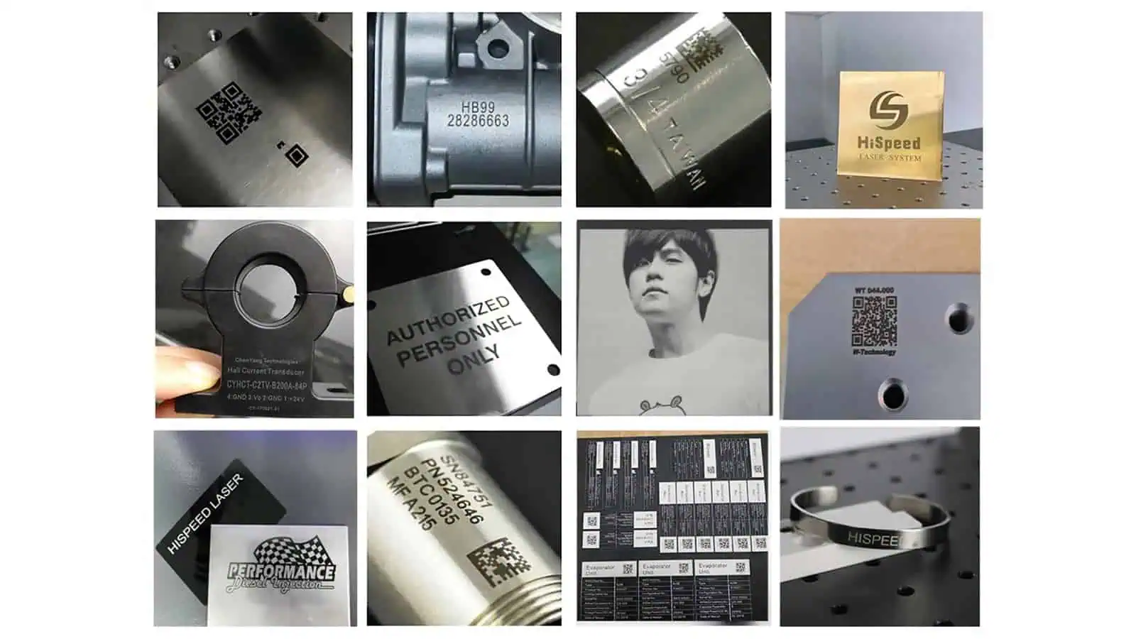
Fiber Laser Samples
Representative sample results for metals and other materials commonly evaluated with fiber laser marking.
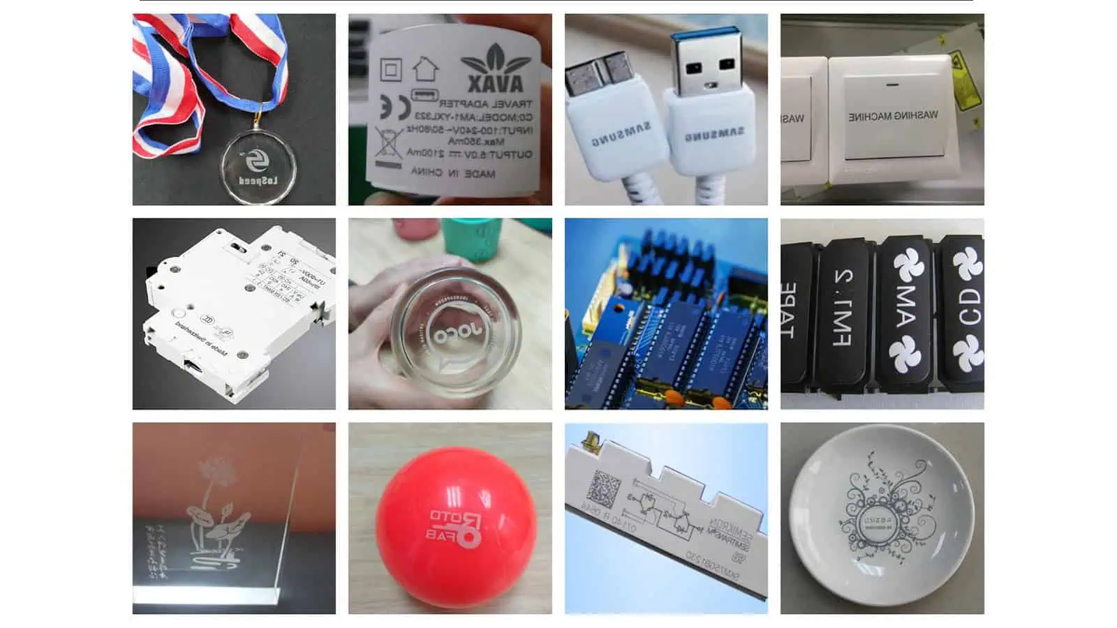
UV Laser Samples
Representative sample results for fine marking and materials that benefit from lower thermal impact.
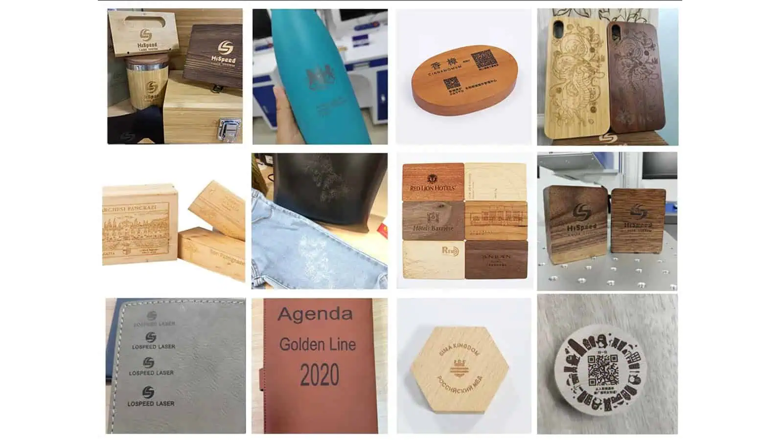
CO₂ Laser Samples
Representative sample results for organic materials and other surfaces commonly evaluated with CO₂ laser marking.
Why testing matters: a visually acceptable mark can still fail barcode reading, wear, corrosion, cleaning, sterilization, downstream finishing, or cycle-time requirements. Production approval should therefore use representative parts and agreed acceptance criteria before the machine configuration is finalized.
Choose the Next Route
Start with the Question You Need to Solve
Use this Materials hub while the main uncertainty is the substrate or surface. Once the material route is clear, move to the page that matches the next production decision instead of trying to solve every question from the material name alone.
| What you need to decide now | Best route | What you will evaluate there |
|---|---|---|
| How will this exact material, coating, or surface respond to laser marking? | Materials | Material behavior, surface stack, likely marking mechanism, process risk, and sample-test requirements. |
| How should this automotive, electronics, medical, packaging, battery, jewelry, or other product be marked in production? | Applications | Part geometry, marking content, production task, throughput, quality checks, traceability, and validation context. |
| Which standard machine family or machine structure should I compare? | Products | Machine families, enclosure or open structures, laser-source directions, field-size options, and sellable configurations. |
| Do I need rotary marking, vision positioning, conveyor marking, 3D focus, multi-axis motion, or automation? | Solutions | Positioning, motion, integration method, fixtures, data flow, automation interfaces, and project evaluation. |
FAQ
Materials Laser Marking FAQs
What materials can a laser marking machine mark?
Laser systems can be evaluated for metals, plastics, glass, ceramics, wood, leather, paper, textiles, electronic substrates, coatings, stone, and composites. Compatibility depends on the exact formulation, surface, and required result.
Is one laser source suitable for every material?
No. Fiber, MOPA fiber, UV, CO2, and project-reviewed green laser options interact differently with materials and surfaces. Green should only be considered when the configuration is available and the material trial supports it. A sample-led comparison is often the safest selection method.
Why do two parts made from the same plastic mark differently?
Colorants, fillers, flame retardants, laser additives, molding conditions, and surface texture can change absorption and contrast even when the resin family is the same.
Can a material be approved without testing a real sample?
A preliminary route can be proposed from material data, but production approval should use the final material, surface, and geometry with agreed acceptance criteria.
What should I send for a material test?
Send representative parts or coupons, material and coating information, the artwork or code, target result, mark location, cycle requirement, durability criteria, and any SDS or safety constraints.
From Material Screening to Sample Evaluation
Send the Actual Part Before Finalizing the Laser and Machine Direction
Include the final substrate or coated part, material or coating information, artwork or code, target contrast or depth, mark position, cycle requirement, durability criteria, and any SDS or safety constraints. This gives the sample evaluation enough context to support a practical machine recommendation.