Zhuorui Laser / technical reference
Laser Marking Technology Guides
Use this guide to compare Fiber, UV, CO2 and Green laser-marking routes, understand when MOPA fiber matters, and identify which technology is worth testing first for the real material and target mark. Then use wavelength, pulse behavior, F-theta focusing optics and galvo scanning to understand why the process window changes.
How to use this guide: Start with the material and target effect. Use the quick selection matrix for a first route, then use the technology map and parameter relationships to understand the variables behind that choice. Check the relevant product page for machine configuration, the material guide for substrate response, and the solution page when the decision involves integration or production workflow.
The five variables
Laser Marking Technology: Five Variables to Understand
A laser specification is useful only when its variables are read together. Start with the material and target effect, then use these five lenses to frame the right test.
Laser source
Defines the family of emitted light and the practical process window available for the material.
Wavelength
Changes absorption, reflectivity and how the surface converts optical energy into a mark.
Pulse behavior
Pulse width, frequency and peak power shape heat input, removal and edge quality.
Spot size & focusing optics
The F-theta lens and focal length shape the focused spot, working distance and usable field, which in turn affect feature scale and local energy density.
Galvo scanning
The galvo scan head steers the beam across the X-Y field and controls beam position and scan speed. Focusing is handled by the F-theta optics, not by the galvo.
From energy to mark
How those variables become a visible laser mark
Laser marking starts only when the surface absorbs enough optical energy to change the material in a useful, controlled way. Wavelength and surface condition influence how much energy is absorbed; pulse behavior and the F-theta focusing optics shape the focused spot and local energy density; and the galvo scan head positions and moves that focused beam across the surface. The visible result is therefore the end of a chain of interactions, not the effect of one specification in isolation.
On metals, the process may create a dark surface reaction or oxide layer with little material removal, remove a thin surface layer for a lighter mark, or remove more material for engraving. On polymers and organic materials, the absorbed energy may produce foaming, carbonization, a chemical colour change or controlled removal. Coatings can be selectively removed to expose a contrasting layer underneath. Glass and other brittle or transparent materials may respond through localized surface modification or frosting, where the acceptable process window depends strongly on composition, coating and thermal sensitivity.
This is why two parts with the same broad material name can behave differently. Alloy grade, pigments, additives, anodizing, paint, plating, surface finish and layer thickness can all move the useful process window. A technology guide can identify the mechanism worth testing, but a representative sample is still needed to confirm contrast, depth, surface damage, readability and repeatability on the real part.
Wavelength, material and surface state determine how optical energy enters the part.
Absorbed energy drives heating, chemical change, oxidation, foaming or material removal.
Pulse behavior, focused spot, galvo scan speed, spacing and passes control overlap, heat accumulation and feature shape.
Inspect the real sample for contrast, depth, edge quality, damage, readability and process stability.
Source family directory
Fiber, UV, CO2 and Green Laser Marking Technologies
These four routes are technical starting points, not universal material promises. The real surface, mark objective and sample acceptance decide the final configuration.
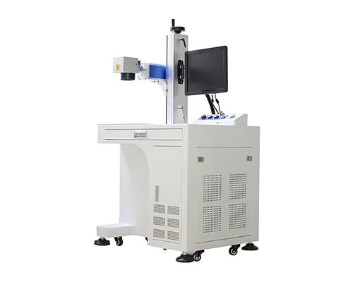
Near-infrared / commonly around 1064 nm
Fiber laser technology
Common starting route for metals and selected engineered materials. Q-switched and MOPA architectures differ in pulse control and process window.
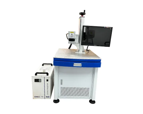
Ultraviolet / commonly 355 nm
UV laser technology
Often evaluated for fine detail and sensitive surfaces where a shorter wavelength may produce a useful process window.
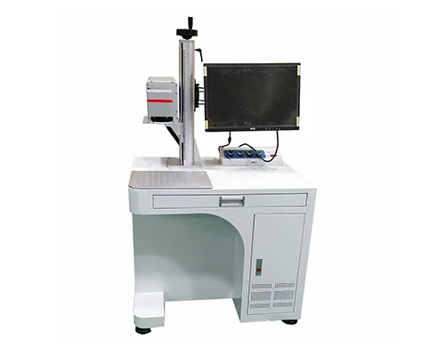
Infrared / commonly 10.6 µm
CO2 laser technology
Longer-wavelength route for selected organic materials, coatings and packaging, with extraction and plume behavior in scope.
Visible green / commonly 532 nm
Green laser technology
Green sources can be relevant where absorption or thermal response makes a visible-wavelength trial worthwhile. Confirm source availability against the proposed machine configuration.
Quick first-pass selection
Which laser technology is worth testing first?
Use this as a routing matrix, not a compatibility guarantee. The first route should be chosen from the real material, surface stack and target effect, then confirmed on a representative sample.
| Material / target | Technology worth testing first | Why it is a common starting point | What can change the decision |
|---|---|---|---|
| Bare metals, durable identification, engraving or dark marks | Fiber; consider MOPA fiber when a wider pulse-control window matters | Near-infrared fiber sources are a common industrial route for metals and robust parts. | Alloy, surface finish, coating, target colour, required depth, heat input and field size. |
| Heat-sensitive plastics, films or fine high-contrast marks | UV is often worth testing early | Shorter wavelength and localized interaction can open a useful process window on sensitive or difficult substrates. | Polymer formulation, pigment, additives, colour, thickness, haze, residue and allowable heat effect. |
| Wood, paper, leather, cardboard and many organic surfaces | CO2 | CO2 is a common route for organic and many non-metallic materials. | Moisture, coating, char tolerance, edge quality, required contrast, focus and extraction. |
| Glass, transparent or brittle surfaces | UV or CO2, depending on the material and target effect | Both routes can be relevant, but the desired frosting, surface change or coating response may be very different. | Glass composition, coating, thickness, cracking risk, mark depth, optical appearance and thermal sensitivity. |
| Painted, anodized, plated or multi-layer surfaces | Depends on whether the goal is colour change, coating removal or substrate engraving | The best route is governed by which layer must absorb or be removed without damaging the layer below. | Coating chemistry, layer thickness, substrate, selectivity, edge quality and acceptable heat-affected area. |
| Special absorption or tightly controlled thermal cases | Green or another specialist source may be worth evaluating | A different wavelength can change absorption and thermal response enough to create a workable process window. | Actual absorption, source availability, stability, cooling, geometry and sample evidence. |
Important: MOPA is not a separate wavelength family from fiber; it is a fiber-laser architecture used when broader pulse-control flexibility is valuable.
Parameter relationships
How Laser Marking Parameters Affect the Result
Use this matrix to identify which specifications matter and what evidence to request. Final equipment details should be checked against the proposed machine configuration, and marking results should be confirmed on a representative sample.
| Variable | What it controls | What can change on the part | Evidence to request |
|---|---|---|---|
| Source | Emitted light family and available process architecture | Absorption route, mark mechanism, cooling and maintenance boundary | Source model, datasheet, installed configuration and service scope |
| Wavelength | Interaction with the material and surface stack | Contrast, reflectivity, haze, residue, removal or thermal response | Real-surface sample at the proposed wavelength |
| Pulse width and frequency | Energy delivered per pulse and pulse timing | Heat input, edge quality, colour window, depth and throughput | Parameter window, pulse range and repeatability data |
| F-theta focusing / spot size | Focus geometry, focused spot size, working distance and optical field | Line width, detail, local energy density, depth and tolerance to focus drift | F-theta lens, focal length, working distance, marking field and measured mark detail |
| Galvo scanning | Beam steering, X-Y positioning and scan speed across the defined optical field | Path accuracy, corner behavior, line placement, scan speed and laser-on time | Scan-head model, commanded vs measured speed, field calibration and geometric accuracy test |
Configuration vs tuning
System variables and adjustable laser marking parameters are not the same thing
The machine configuration defines the process window available to you; the adjustable parameters tune how that available energy is delivered to the real surface. The exact controls available depend on the source architecture and controller. Pulse width, for example, is not an independent user-adjustable setting on every laser source and should only be treated as adjustable when the installed configuration exposes that control. Separating the two prevents a common mistake: trying to solve a wavelength, optics or field-size problem only by changing power or speed. In the beam-delivery chain, the galvo scan head steers the beam, while the F-theta lens focuses it and maps that deflection across the working field; they are related components but they do different jobs.
| Layer | Typical variables | What they decide | What to record during testing |
|---|---|---|---|
| System / optical configuration | Source family, wavelength, pulse architecture, lens, focal length, marking field and spot size | Sets the physical interaction route, available pulse behavior, focus geometry and practical energy-density range. These are normally chosen when the machine is configured. | Source model, wavelength, pulse capability, lens, field size, focal distance and installed configuration. |
| Adjustable process settings | Power, scan speed, frequency, pulse width, hatch spacing, number of passes and focus offset | Changes energy per unit area, pulse overlap, heat accumulation, removal rate, line appearance and cycle time inside the available process window. | Parameter set, mark size, fill strategy, focus position, pass count, measured result and repeatability across samples. |
A useful parameter window is a combination, not a single “correct” number. Higher power can be offset by faster scanning, different pulse timing, wider spacing or fewer passes, while a lens or wavelength change may move the process into a completely different operating window.
How to use the guides
What to Include in a Laser Marking Test Brief
A good brief makes the next experiment measurable. Capture the part, the mark and the operating boundary before asking for a power recommendation.
- Define the surface: alloy, polymer, glass, coating, ink, laminate, adhesive, finish and batch variation.
- Define the effect: contrast, dark mark, colour, frosting, surface removal, depth, code readability or cosmetic detail.
- Define the geometry: flat, curved, stepped, recessed, cylindrical, transparent, thin-wall or multi-level.
- Define the production: part presentation, fixture, cycle target, data input, inspection and acceptable variation.
- Define acceptance criteria: contrast, depth, readability, cosmetic limits, allowable heat effect, durability or cycle-time requirement—the conditions that determine whether the sample passes.
- Define the boundary: source, wavelength, pulse, spot, field, focus, extraction, cooling, guarding and destination requirements.
Related technical guides
Related Laser Marking Guides and References
Choose the topic that matches the question you need to solve. The source-specific Fiber, UV, CO2 and Green guides are linked above; these related references cover foundations, pulse control, configuration, optics and safety.
How Laser Marking Works
Energy, absorption, scanning and material response from first principles.
Open the fundamentals guide >MOPA Laser Technology
How MOPA and Q-switched architectures create different parameter windows.
Open the MOPA guide >Power, Field Size & Configuration
Why power, lens, field, frequency and pulse must be read together.
Open the configuration reference >Field Size, Focal Length & Energy Density
How focal distance, spot size and field choice affect the mark.
Open the optics guide >Safety & Compliance
Beam path, guarding, extraction, maintenance and destination requirements.
Open the safety reference >Buyer questions
Laser Marking Technology FAQ
Which laser source should I choose first?
Start with the material, surface stack and target effect. Use the quick selection matrix to identify a first route, then compare wavelength, pulse behavior, F-theta focusing / spot size and galvo scanning requirements. Confirm the final source and process window on the real surface.
Is wavelength the same as laser source?
No. Source describes the laser architecture or family; wavelength describes the emitted light. A source family may have a defined wavelength range, but both source and wavelength should be confirmed in the actual product configuration.
Does higher power always mark faster or better?
No. Power is only one variable. Pulse width, frequency, spot size, scan field, material absorption, mark effect and complete cycle can change the result more than a headline wattage.
Does a smaller spot always produce a better mark?
No. A smaller spot can support finer detail and higher local energy density, but focus tolerance, field size, surface variation, required depth and production stability still matter.
What is the difference between scan speed and production cycle time?
Scan speed describes beam movement during marking. Production cycle also includes loading, positioning, focusing, data transfer, inspection, unloading and any line synchronization.
Can these guides confirm a material result?
No. They explain the technical variables. Material and application pages can frame the feasibility question, while a documented sample test confirms the actual mark, acceptance criteria and limitations.
Next step
Bring the actual part into the technical conversation
Send the part or drawing, material and surface stack, artwork, target effect, mark size, geometry, cycle target and any data or safety requirements. Zhuorui can review these inputs and map the source, wavelength, pulse behavior, F-theta focusing optics and galvo scanning requirements into a sample-first test plan.