
MOPA Fiber Laser Technology
MOPA is not a separate laser wavelength family like UV or CO₂. In industrial laser marking, the term usually refers to a pulsed fiber-laser architecture that gives the process engineer greater control over pulse duration and related pulse behavior than a conventional Q-switched fiber source.
That distinction matters because marking quality is not determined by average wattage alone. Two fiber sources can operate in the same near-infrared wavelength range and have similar rated average power, yet interact differently with the same surface because their pulse energy, pulse duration, repetition rate, peak-power behavior, and allowable operating combinations are different.
The practical value of MOPA is therefore not that it is a universally “better fiber laser.” Its value is a wider process-development window when the required result depends on controlling how energy reaches and modifies the material surface.
This can matter for stainless-steel color effects, dark marking on suitable anodized aluminum, selected plastics, thin components, coatings, and other appearance- or heat-sensitive applications. It may add little practical value when a conventional Q-switched fiber process already achieves the required contrast, depth, throughput, and repeatability.
The central selection question is therefore not whether MOPA is more advanced, but whether the required marking result actually needs the additional pulse-control range that MOPA provides.
What Is a MOPA Fiber Laser?
MOPA stands for Master Oscillator Power Amplifier.
In a MOPA architecture, the master oscillator creates a lower-power seed signal with defined optical characteristics, and the amplifier stage increases that signal to the required output level. The important point is that pulse generation and final power amplification are separated.
Coherent’s explanation of MOPA technology describes the architecture in the same way: the oscillator establishes important characteristics of the laser signal and the amplifier raises the output power while preserving the required signal properties.
MOPA therefore describes an architecture, not a wavelength. MOPA architectures can exist outside industrial fiber marking. In the marking-machine market, however, “MOPA laser” normally refers to a pulsed fiber source operating in the near-infrared region, commonly around 1064 nm.
A MOPA marking laser is therefore still a fiber laser. This is why the popular search phrase “MOPA vs fiber laser” is technically imprecise. For industrial marking, the more useful comparison is usually MOPA fiber laser vs conventional Q-switched fiber laser.
Both technologies can operate in approximately the same wavelength family and both can mark many metals effectively. The important difference is how the pulse is generated and how much freedom the process engineer has to control its behavior.
How Does a MOPA Fiber Laser Work?
In a conventional Q-switched fiber laser, energy builds in the gain medium and is released in short pulses through Q-switching. Pulse duration, pulse shape, and peak-power behavior are related to the source design and operating point. It is therefore too simplistic to say that every Q-switched source has one absolutely fixed pulse width; the more accurate distinction is that its practical pulse-control range is generally more constrained.
A MOPA architecture forms the seed pulse first and amplifies it afterward. Because pulse formation and final amplification are separated, a marking-oriented MOPA source can be designed to provide a broader range of selectable pulse durations and operating combinations.
Coherent’s laser-marking technical overview distinguishes Q-switched and MOPA pulsed fiber sources primarily through this difference in pulse behavior. The important practical consequence is not simply that the operator receives “more settings.” The engineer gains a larger parameter space in which to establish a usable process window.
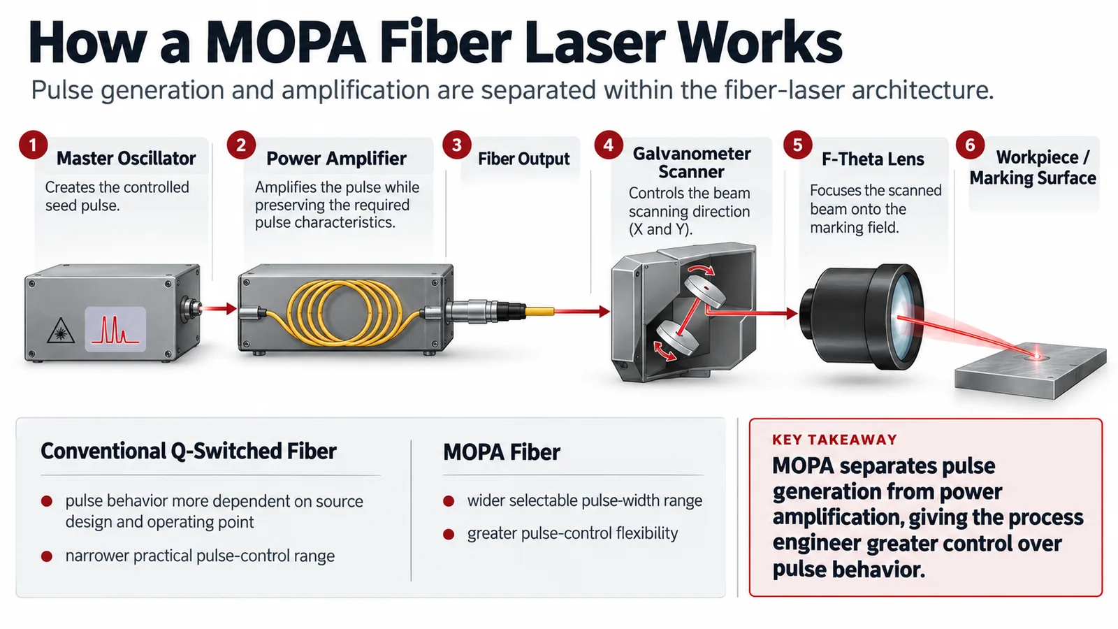
This also explains why the word MOPA alone does not fully describe machine capability. Two MOPA sources can have different pulse-width ranges, repetition-rate limits, pulse-energy behavior, beam quality, and allowable operating combinations even when their nominal average power is similar.
For technical comparison, the useful question is therefore not only “Is this a MOPA laser?” but also which MOPA source is installed and what operating window that source actually provides.
Why Do Pulse Width and Frequency Matter in Laser Marking?
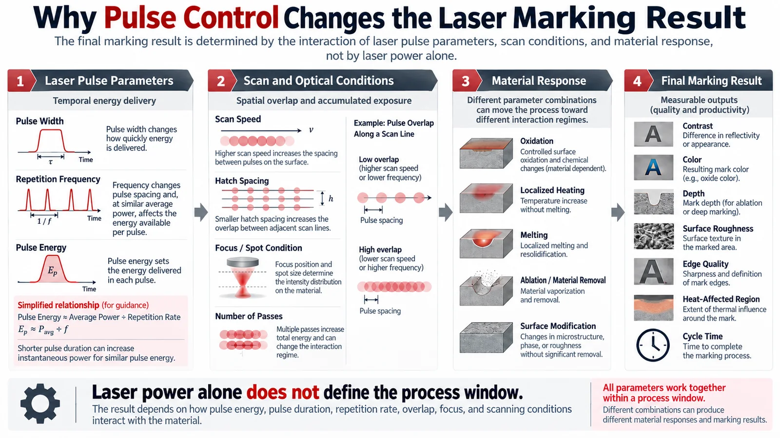
This is the key technical concept behind MOPA. A pulsed laser does not deliver energy continuously; it delivers discrete pulses. The material response depends on how much energy each pulse carries, how long the pulse lasts, how frequently pulses arrive, and how those pulses overlap while the scanner moves across the workpiece.
For a regular pulse train, pulse energy can be approximated as:
Pulse energy = average power ÷ repetition rate
This relationship, also described in RP Photonics’ pulse-energy reference, immediately shows why repetition frequency cannot be treated as an isolated setting. If average output remains similar while repetition rate increases, the available energy in each individual pulse generally decreases. At the same time, more pulses are being emitted every second.
Pulse Width Changes How the Energy Is Delivered
Pulse duration determines the time over which each pulse releases its energy. As a first-order concept, delivering similar pulse energy over a shorter period produces higher instantaneous power than delivering it over a longer period. Actual peak power still depends on pulse shape and source design, so this relationship is best used to understand the process rather than as a universal machine specification.
At the material surface, changing the pulse regime can alter the balance between rapid localized heating, thermal diffusion, oxide formation, melting, material removal, coating modification, and surface damage.
This is why the common statement “shorter pulse means less heat” is incomplete. A short pulse operated with high pulse energy, heavy pulse overlap, slow scanning, narrow hatch spacing, or repeated passes can still create substantial accumulated heating. Conversely, a longer pulse may be exactly what a particular thermal marking mechanism requires.
The engineering objective is therefore not to minimize pulse width. It is to identify which pulse regime creates the required surface response without crossing the unacceptable damage boundary.
Frequency Changes Pulse Energy and Pulse Spacing
Repetition rate determines how many pulses are emitted each second, but the result at the workpiece also depends on scanner movement. If frequency increases while scan speed remains unchanged, more pulses are deposited along the same distance. Pulse spacing becomes smaller and overlap increases.
That can help when a process needs more uniform accumulated heating or a continuous-looking surface modification. It can also create excessive heat when overlap becomes too large. At approximately constant average power, increasing frequency also reduces energy available in each individual pulse.
Frequency therefore changes both the temporal and spatial character of the process. This is why instructions such as “increase frequency for a darker mark” or “use the shortest pulse for less heat” are not reliable engineering rules without the rest of the process conditions.
For a deeper parameter-level explanation, see the Pulse Width and Frequency Guide.
Scan Speed, Hatch, Focus, and Passes Complete the Process Window
Pulse width and frequency describe source behavior, but the scanner and optics determine how those pulses are distributed across the workpiece. Reducing scan speed normally increases the number of pulses delivered along a given path. Reducing hatch spacing increases overlap between neighboring fill lines. Additional passes accumulate further exposure, while focus and lens selection influence spot condition and local energy density.
The useful engineering chain is therefore:
Pulse width + repetition rate + pulse energy → temporal energy delivery
combined with:
Scan speed + hatch spacing + focus + passes → spatial overlap and accumulated exposure
which together determine the balance between oxidation, heating, melting, ablation, coating response, and other surface mechanisms. Those mechanisms then determine practical outputs such as contrast, color, depth, roughness, edge condition, thermal effect, and cycle time.
This interaction is the real reason MOPA is useful. A wider pulse-control range gives the engineer more combinations to explore, but it also creates more ways to produce either a robust process window or an unstable one.
What Are the Advantages of MOPA Fiber Lasers?
The main advantage of MOPA is process flexibility. A conventional Q-switched fiber source can already perform many industrial marking tasks extremely well. MOPA becomes valuable when the required result is sensitive to how the pulse interacts with the surface rather than simply whether sufficient laser energy is available.
The wider pulse-control range can be particularly useful for appearance-sensitive processes. A customer may require a controlled dark mark rather than ordinary engraving, or a colored stainless-steel surface rather than a conventional identification mark. A plastic component may need strong contrast without excessive melting or foaming. A thin or coated component may allow very little visible thermal damage.
In these situations, the additional pulse range gives the engineer more ways to adjust the relationship between pulse energy, pulse duration, accumulated heating, and surface modification.
The same flexibility can be valuable in mixed production environments. A factory running one established mark on one consistent material may gain little from a very broad adjustment range. A job shop or OEM supplier processing several alloys, coatings, plastic formulations, and appearance requirements can gain considerably more value from the ability to establish several different process windows on the same platform.
The useful advantage is therefore not that “MOPA produces better marks.” It is that MOPA gives the engineer more ways to find a process that satisfies a difficult acceptance requirement.
What Are the Limitations of MOPA Fiber Lasers?
The wider parameter range that makes MOPA useful also creates one of its main limitations: more flexibility means more process-development work.
A larger parameter space provides more opportunities to find a suitable operating window, but it also creates more combinations that can produce an attractive sample without being suitable for stable production. A setting can produce excellent contrast while being too slow, too sensitive to focus variation, too aggressive on the surface, or too inconsistent across material batches.
MOPA systems also generally carry a price premium over basic Q-switched fiber systems. That premium only creates value when the additional pulse-control range solves a real manufacturing requirement. For a stable serial number, logo, QR code, or established metal-marking process, conventional fiber may already provide the required quality and throughput.
MOPA should also not be assumed to engrave deeper simply because it provides more pulse control. Deep engraving depends on the complete removal process, including pulse energy, average power, spot condition, material, pulse behavior, overlap, scanning strategy, pass count, removal efficiency, and allowable cycle time. A suitable Q-switched source can remain the more efficient solution for some engraving tasks.
Most importantly, MOPA cannot correct the wrong wavelength choice. Pulse control changes how energy is delivered at the source wavelength; it does not change the underlying wavelength-material interaction. If near-infrared radiation is poorly suited to the material or creates unacceptable thermal effects, UV or CO₂ may provide the more appropriate route.
Which Materials Are Suitable for MOPA Laser Marking?
Industrial MOPA fiber sources are naturally strong candidates for many metals because near-infrared fiber lasers already interact effectively with a wide range of metallic surfaces.
A material being markable with MOPA does not mean that the material requires MOPA.
Stainless Steel
Stainless steel demonstrates this distinction clearly. A normal serial number, logo, or engraved identification mark can often be produced efficiently with conventional fiber. When the requirement changes to controlled color, a particular dark appearance, or another surface-sensitive effect, pulse behavior becomes much more important.
Laser-induced color on stainless steel involves surface modification and oxide formation rather than simple material removal. Peer-reviewed research on nanosecond laser coloration of stainless steel has shown that resulting colors depend on oxide-film characteristics and the interaction of variables such as power, scanning speed, pulse width, repetition rate, and surface condition.
The practical lesson is that stainless-steel color is not controlled by pulse width alone. MOPA provides more variables with which to establish the required thermal and oxidation process, but alloy, finish, cleanliness, focus, scanning strategy, and acceptance method still influence the result.
Aluminum and Anodized Aluminum
Bare aluminum and anodized aluminum should be treated as different process problems. A conventional process may remove or modify an anodized layer, while a dark MOPA process can be developed to create a dark surface appearance under suitable anodizing and process conditions without simply treating the task as ordinary coating removal.
Trotec’s anodized-aluminum application guidance also makes the important point that anodized layers and surface finishes vary, so published settings have to be adjusted to the real workpiece.
This is a good example of why “aluminum” is not a complete process specification. The useful description is closer to: bare or anodized aluminum, surface finish, anodized-layer condition, and required final appearance.
Other Metals
Carbon steel, alloy steel, titanium, and many other metals are already compatible with conventional fiber-laser marking. MOPA becomes more relevant when an additional constraint is introduced, such as a narrow thermal tolerance, appearance requirement, thin geometry, coating preservation, unusual contrast target, or the need to run several different marking modes on the same machine.
For ordinary identification or straightforward engraving, the MOPA architecture itself may provide little practical advantage.
Selected Plastics
Plastics require more caution because the polymer name alone does not predict laser response. Two components both described as ABS, for example, can contain different pigments, fillers, flame retardants, or laser-sensitive additives and can therefore react differently to the same near-infrared process.
Depending on formulation, the visible mark may result from carbonization, foaming, localized melting, additive-mediated color change, or another material response. MOPA can be useful when the material already responds to the fiber wavelength but the process requires greater control over heat, contrast, or surface disturbance.
If the real problem is poor near-infrared interaction or excessive thermal damage, changing to UV may provide more value than continuing to optimize MOPA parameters.
Which Applications Benefit Most from MOPA Pulse Control?
The strongest MOPA applications are usually not defined only by material name. They are applications in which the required acceptance result depends strongly on controlling the surface-response mechanism.

Stainless-Steel Color Marking
Color marking on stainless steel is a process-window problem rather than simply a question of whether a laser can mark steel. The visible result depends on surface modification and oxide-layer behavior, which in turn depend on the complete thermal history created during scanning.
This explains why copying another user’s “blue stainless” parameter set often fails. The same displayed pulse width and frequency do not guarantee the same workpiece response if the source model, lens, focus, alloy, surface finish, power, speed, or hatch strategy changes.
The engineering objective is not to create one attractive colored square. It is to establish a repeatable color process window that remains acceptable under realistic production variation.
Dark Marking on Anodized Aluminum
MOPA can also be valuable when the target is a deep dark appearance on a suitable anodized aluminum surface. This should not be confused with simply removing the anodized layer and exposing the base metal. The desired surface mechanism and visual result are different.
The useful project definition is therefore not “black aluminum.” It should state what aluminum surface is being processed, what anodized or coated layer is present, and whether the target is coating removal, cosmetic black appearance, machine-readable contrast, or another defined result.
Plastic Marking with Tight Thermal Limits
On selected plastics, the additional pulse-control range can help when strong contrast must be achieved without excessive melting, foaming, edge damage, or deformation. But MOPA remains only one possible route.
If the polymer responds poorly to the near-infrared wavelength itself, UV may be more appropriate. That is a wavelength-selection problem rather than a pulse-width problem.
Thin and Appearance-Sensitive Parts
Electronic housings, thin sheet components, decorative hardware, coated parts, and other appearance-sensitive workpieces can benefit when excessive heating creates discoloration, deformation, surface swelling, or coating damage.
Here again, shorter pulse width by itself is not the solution. A short pulse combined with excessive overlap, slow scanning, or repeated passes can still generate substantial accumulated heat. The process must be judged from the total energy-delivery pattern.
Fine Identification Marks
Small Data Matrix codes, QR codes, fine characters, and dense graphics can benefit from a controlled process window when contrast must be achieved without degrading small edges or modules.
MOPA can provide an additional variable for controlling the material response, but it cannot compensate for unsuitable optics, incorrect focus, poor fixturing, unstable positioning, or features that are too small for the complete optical and scanning system.
What Risks, Precautions, and Common Mistakes Should You Know?
MOPA’s larger parameter space makes disciplined process development more important, not less important.
Copying Parameter Recipes Without Understanding the System
One of the most common mistakes is treating published settings as transferable recipes. A value such as “8 ns, 200 kHz, 1500 mm/s” only has meaning within the source, power, lens, material, focus, hatch, and scanning conditions under which it was developed.
A different MOPA source may deliver different pulse energy or pulse shape at the same displayed pulse width and frequency. A different lens changes the spot condition, while a different anodized layer or polymer formulation changes the material response.
Useful published settings should therefore be treated as starting references for controlled testing, not production guarantees.
Changing Too Many Variables at Once
Random tuning is another common problem. If pulse width, frequency, power, scan speed, and hatch spacing all change simultaneously and the mark suddenly becomes darker, the operator may have found an attractive sample but has learned very little about why the process improved.
A better method is to change variables with a specific engineering question in mind. If a surface is melting, for example, the engineer may need to distinguish excessive pulse energy from accumulated heating caused by heavy overlap. Frequency, pulse width, speed, and hatch can then be adjusted in a way that helps discriminate between those causes.
This produces process knowledge instead of a collection of lucky settings.
Treating the Shortest Pulse as the Safest Pulse
The minimum pulse width is not automatically the optimum setting. Shorter pulses can change peak-power behavior and reduce the time available for heat diffusion during an individual pulse, but total thermal behavior still depends on repetition rate, pulse energy, scan speed, overlap, hatch spacing, and pass count.
The target is not the shortest possible pulse. The target is the pulse regime that produces the required material response with acceptable process margin.
Assuming Every MOPA Source Is Equivalent
A specification such as “30 W MOPA” is incomplete. Two 30 W MOPA sources can have different pulse-width ranges, repetition-rate limits, pulse energies, beam characteristics, and usable operating combinations.
This becomes particularly important when comparing quotations from different machine suppliers. The source manufacturer and exact model should be confirmed before assuming two machines have equivalent process capability.
Ignoring Surface Variation
Laser marking is a surface process, so surface variation matters. Changes in anodizing, coating chemistry, polishing, brushing, oxidation, contamination, oil, cleaning state, or supplier condition can change the mark even when the base material designation is unchanged.
This is why a test coupon from another supplier can prove general feasibility while still providing false confidence about the production part.
Confusing a Successful Sample with Production Validation
A visually successful mark demonstrates that the required effect can be produced under those particular conditions. It does not prove that the process is tolerant to focus shift, material-batch variation, production handling, part temperature, long-run operation, or the required production cycle time.
A good sample demonstrates feasibility. A production process demonstrates repeatability.
Reflective Materials and System Protection
Reflective metals such as aluminum, copper, brass, gold, and silver can introduce additional system considerations because reflected optical energy can return toward the laser source. The significance depends on material, finish, source architecture, optics, and process conditions.
Source compatibility and back-reflection protection should therefore be confirmed for demanding reflective-material applications instead of assuming that every fiber source provides equivalent protection.
Laser Safety and Extraction
MOPA does not change the fundamental safety responsibilities associated with high-power industrial laser marking. Direct or reflected laser radiation can present serious eye and skin hazards, and some marking processes can generate airborne particles, smoke, vapors, or coating-decomposition products.
OSHA’s laser-hazard guidance identifies direct and reflected beam exposure, fire hazards, and laser-generated airborne contaminants among the relevant risks for high-power laser use.
Machine enclosure, interlocks, access control, viewing protection, extraction, and fire-risk controls should be determined from the actual system and process. For adjacent guidance, see Zhuorui Laser’s Laser Safety & Compliance resources.
MOPA vs Q-Switched Fiber Laser: What Is the Difference?
This is the most important direct comparison because both systems can belong to the same pulsed fiber-laser family. The difference is not primarily wavelength. It is the available pulse behavior and the resulting process-development flexibility.
| Comparison | Conventional Q-Switched Fiber | MOPA Fiber |
|---|---|---|
| Technology family | Pulsed fiber laser | Pulsed fiber laser |
| Typical marking wavelength | Near 1 µm | Near 1 µm |
| Pulse generation | Q-switched | Master oscillator + power amplifier |
| Pulse-width behavior | More dependent on source design and operating point | Broader selectable range on suitable sources |
| Operating flexibility | More constrained | Wider pulse/frequency adjustment window |
| Standard metal identification | Strong | Strong |
| Conventional engraving | Strong with a suitable source | Strong with a suitable source |
| Appearance-sensitive processes | Less adjustment freedom | Greater process-development flexibility |
| Stainless-steel color | Possible under suitable source and process conditions | Common reason to evaluate MOPA |
| Dark anodized-aluminum marking | Source/process dependent | Important MOPA application |
| Selected plastics | Material dependent | Greater tuning potential when near-infrared response is suitable |
| Parameter development | Usually simpler | More variables to qualify |
| Typical equipment cost | Lower | Higher |
The word better is therefore not meaningful without an application.
Consider a conventional stainless-steel serial number. If the requirement is permanence, readable contrast, short cycle time, and stable production, a Q-switched fiber source may already satisfy every important criterion. Additional pulse flexibility creates little value if there is no unresolved process problem.
Now consider an appearance-controlled mark on a thin stainless-steel component where thermal effect, color, surface condition, or edge appearance must remain within a tight tolerance. The additional MOPA pulse-control range now has a clear engineering purpose.
Choose MOPA when additional pulse control solves a requirement—not because MOPA is positioned as a higher-tier product.
For a more focused side-by-side selection discussion, see MOPA vs Q-Switched Fiber Laser.
MOPA vs UV and CO₂ Lasers: When Does Wavelength Matter More Than Pulse Control?
MOPA vs Q-switched is mainly a pulse-architecture comparison within fiber technology. MOPA vs UV or CO₂ is different because the wavelength also changes.
| Technology | Typical Wavelength | Main Selection Logic |
|---|---|---|
| Q-switched fiber | ~1064 nm | General metal marking and engraving |
| MOPA fiber | ~1064 nm | Fiber processing with wider pulse-control flexibility |
| UV | ~355 nm | Fine processing and many heat-sensitive materials |
| CO₂ | ~10.6 µm | Strong interaction with many organic materials and polymers |
MOPA vs UV
If a material already responds well to the near-infrared fiber wavelength and the main challenge is controlling thermal history, surface appearance, or another pulse-sensitive effect, MOPA is a logical technology to evaluate.
If the problem is poor near-infrared interaction or unacceptable thermal damage, however, wavelength itself may be the limiting factor. UV can interact differently with polymers and other sensitive materials and is widely used where very fine marking with limited unwanted thermal effect is required.
The useful decision is therefore not “Is MOPA better than UV?” It is whether the application needs greater pulse flexibility around 1064 nm or a different wavelength-material interaction altogether. For the wavelength-specific background, see the UV Laser Marking Technology guide.
MOPA vs CO₂
CO₂ operates in a very different infrared wavelength region and interacts strongly with many organic materials and polymers. This is why wood, paper, leather, textiles, and many acrylic or polymer-processing applications are commonly approached with CO₂ rather than fiber technology.
If the wavelength-material interaction strongly favors CO₂, adding more pulse flexibility to a near-infrared MOPA source does not solve the underlying problem. The CO₂ Laser Marking Technology guide explains that wavelength route in more detail.
Choose an appropriate wavelength family first; then optimize pulse behavior within that family.
How Do You Choose the Right Laser for Your Application?
The laser should be selected from the required result backward, not from the technology name forward. A useful selection process first defines the actual material and surface, the required mark, the defects that are unacceptable, and the production target. Only after those requirements are understood does it make sense to compare source architectures.
| Application Requirement | Strong Starting Candidate | Why |
|---|---|---|
| Standard serial number on steel | Q-switched fiber | Conventional fiber is often sufficient |
| Standard QR or Data Matrix on common metal | Q-switched fiber | Extra pulse flexibility may add little value |
| Stainless-steel color effect | MOPA | Wider pulse-control range supports thermal and oxide-process development |
| Appearance-sensitive black mark | MOPA evaluation | Additional tuning can widen the usable process window |
| Deep dark mark on suitable anodized aluminum | MOPA | Well-established MOPA application |
| Selected plastic with useful near-infrared response but tight heat tolerance | MOPA | Pulse control may improve the process window |
| Plastic suffering unacceptable near-infrared thermal damage | Compare UV | Wavelength may be the real limitation |
| Fine heat-sensitive polymer marking | UV deserves strong consideration | Different absorption and processing behavior may reduce unwanted thermal effects |
| Wood, paper, leather, or textile | CO₂ | More suitable wavelength route for many organic materials |
| Conventional metal deep engraving | Fiber selected around removal requirement | Pulse energy, power, spot condition, and removal efficiency matter more than the MOPA label |
| Mixed metal work with appearance-sensitive requirements | MOPA | Wider operating flexibility may justify the additional cost |
Even apparently simple material descriptions can hide very different tasks. “Aluminum marking,” for example, could mean engraving bare aluminum, removing anodizing to expose the substrate, creating a dark mark in an anodized layer, marking painted aluminum, or producing a machine-readable code on a finished housing.
The selection path should therefore be:
Material and surface → required marking mechanism → acceptance limits → wavelength family → source architecture → power and optics → validation
This approach prevents a common purchasing mistake: choosing the machine first and then trying to force every future application into the technology already purchased.
What Should You Check Before Buying a MOPA Laser?
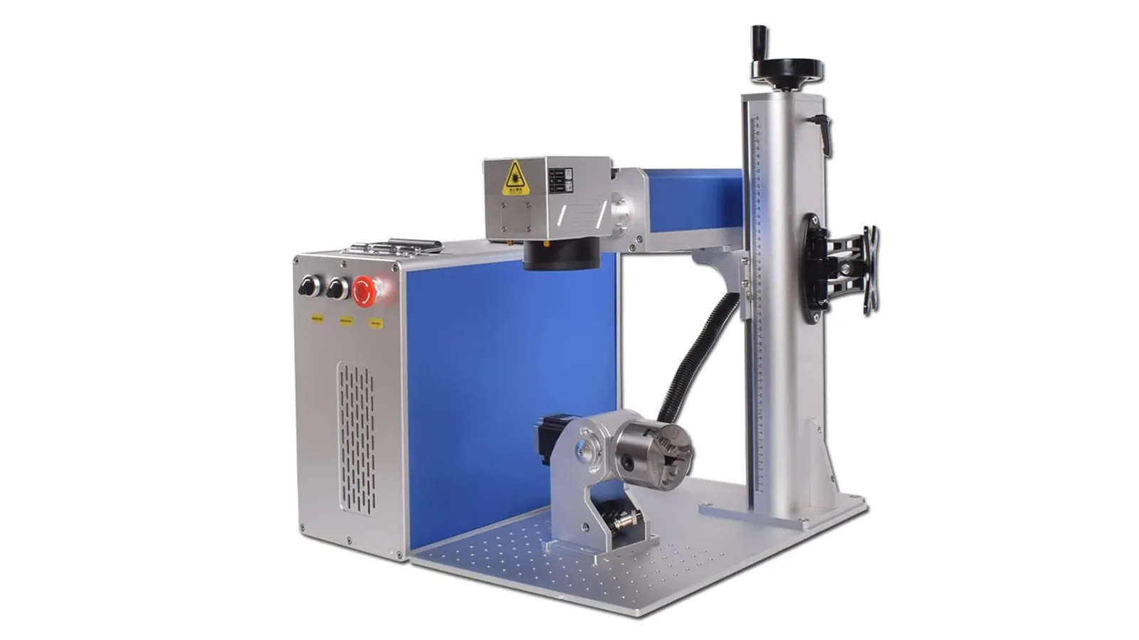
Once MOPA has been identified as a reasonable candidate, purchasing should not be reduced to comparing wattage. A meaningful procurement review has to cover both the laser source and the complete marking system.
| What to Confirm | Why It Matters |
|---|---|
| Laser-source manufacturer and exact model | “MOPA” alone does not define pulse capability |
| Pulse-width range | Determines available temporal-control range |
| Repetition-frequency range and allowed combinations | Pulse width and frequency may not be freely combinable |
| Pulse energy | Important for engraving, removal, and high-intensity processes |
| Average power | Affects available processing capacity but does not define the complete process window |
| Beam quality | Influences focusing and achievable spot characteristics |
| F-theta lens and marking field | Field size and focal length affect spot condition and energy density |
| Galvo and focus system | Affect scanning performance and process repeatability |
| Fixture, rotary, and Z-axis requirements | Determine positioning and focus consistency on real parts |
| Controller and software | Affect parameter control, recipe management, and integration |
| Enclosure and extraction | Affect safety and practical production use |
| Automation interfaces | Matter when the marker becomes part of a production line |
This comparison is far more informative than asking only whether the system is 20 W, 30 W, 60 W, or 100 W.
A MOPA system using a small marking field does not necessarily provide the same workpiece-level process capability as an otherwise similar system using a much larger field lens. Likewise, two sources with the same nominal average power may differ materially in pulse energy, pulse range, and beam characteristics. The Marking Field Size, Focal Length & Energy Density guide covers that optical trade-off separately.
The machine should therefore be evaluated as a complete laser marking system, not merely as a laser-source specification.
How Should You Validate a MOPA Process Before Production?
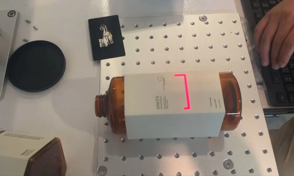
A useful sample test should answer more than “Can the laser make this mark?” The real question is whether a process window exists that remains acceptable under realistic production variation.
Step 1: Define What Counts as an Acceptable Result
Acceptance criteria should reflect the actual function of the mark. Cosmetic work may be judged by darkness, color consistency, edge condition, or surface roughness. Identification marks may instead require a defined level of barcode or Data Matrix readability. Engraving can require a minimum depth, while coated or precision parts can impose limits on coating damage or dimensional change.
Some projects may also require corrosion performance to be considered when marking modifies a functional metal surface. Whatever the quality requirement, it still has to be achieved within an acceptable complete cycle time.
Without a defined acceptance condition, “best parameters” has no technical meaning.
Step 2: Test Production-Representative Material
The sample should match the production part as closely as possible. Nominal material grade alone is not enough when the process depends on surface condition. Supplier, coating, anodizing, color, finish, thickness, and cleaning state may all affect the result.
A successful mark on a convenient test coupon can prove basic feasibility while providing misleading confidence about the actual production surface.
Step 3: Lock the Machine Configuration
The source model, lens, marking field, focus condition, scanner, fixture, and part orientation should be recorded. Without this information, a successful parameter set cannot be reproduced or transferred meaningfully.
Step 4: Change Variables with a Clear Engineering Question
A useful test matrix should not simply generate hundreds of parameter squares. Suppose the surface is melting. The real diagnostic question may be whether the problem comes mainly from excessive energy in each pulse or from accumulated heating caused by excessive overlap.
Frequency, pulse width, scan speed, and hatch spacing can then be changed deliberately to help separate those possibilities. This creates process knowledge instead of simply searching for the darkest or most attractive sample.
Step 5: Evaluate Parameter Interactions
Any promising result should be recorded as a complete process condition. Pulse width, frequency, average power, scan speed, hatch spacing, focus, and pass count work together. A successful result does not belong to one isolated parameter; it belongs to the combination.
Step 6: Test the Margin Around the Preferred Setting
Once a good process has been found, deliberately introduce realistic variation. A minor focus shift, representative material variation, repeated parts, actual production handling, and the complete production artwork can reveal whether the process has useful tolerance or only works at one narrow laboratory point.
Step 7: Include Throughput in the Final Decision
A visually perfect mark is not automatically the best manufacturing process. The final decision must balance mark quality, process stability, cycle time, and system complexity.
This distinction is especially important with MOPA because a large parameter space makes it relatively easy to produce an impressive demonstration sample. Production validation requires more:
Feasible result → understood process behavior → repeatable operating window → production acceptance
That is the point at which MOPA becomes a manufacturing solution rather than simply a flexible laser source.
MOPA Fiber Laser FAQ
Is MOPA a fiber laser?
In industrial marking, yes. MOPA commonly refers to a pulsed fiber-laser architecture. MOPA describes how the signal is generated and amplified; it is not a separate wavelength family like UV or CO₂.
Is MOPA better than a normal fiber laser?
Not universally. MOPA provides a wider pulse-control window, which becomes valuable when the required result depends strongly on heat input, surface appearance, oxidation, melting, or another pulse-sensitive material response. For routine metal identification or an established engraving process, conventional Q-switched fiber may remain simpler and more economical.
Do I need MOPA if I do not need color marking?
Not necessarily. Color marking is only one reason to consider MOPA. Dark anodized-aluminum marking, selected plastics, thin components, coatings, and other thermally sensitive applications may also benefit from additional pulse control. If the work mainly involves conventional identification or engraving on common metals, Q-switched fiber may already satisfy the requirement.
Can a MOPA laser do deep engraving?
Yes, suitable MOPA sources can perform deep engraving. However, engraving performance depends on pulse energy, average power, spot condition, material, overlap, scan strategy, number of passes, and acceptable cycle time. MOPA architecture alone does not guarantee greater engraving depth.
Can MOPA mark plastics?
Yes, some plastics respond well to near-infrared MOPA marking. Additional pulse control can help optimize the material response when the polymer already interacts usefully with the fiber wavelength. Suitability still depends strongly on formulation, pigment, filler, additive, color, and required result. When near-infrared processing produces unacceptable thermal damage or poor contrast, UV should also be evaluated.
Is Higher MOPA Laser Power Always Better?
No. Higher average power increases available processing capacity, but it does not automatically improve contrast, color, edge quality, or thermal control. The result depends on how average power interacts with pulse energy, pulse width, frequency, optics, scanning conditions, and material response.
Can I Copy MOPA Settings from Another Machine?
They can be useful as a starting reference, but they should not be treated as production recipes. Differences in laser source, pulse behavior, lens, spot condition, material, coating, surface finish, and focus can all change the result. Production settings need to be validated on the actual machine and production-representative material.
MOPA should therefore be understood as a process-control architecture, not a performance badge.
Its value comes from providing additional control over pulse behavior when the required mark is sensitive to energy delivery, thermal history, oxidation, melting, material removal, or surface appearance.
For a routine process that already works reliably with Q-switched fiber, the additional complexity and cost may provide little benefit. For a difficult or appearance-sensitive process, the wider MOPA operating window can be extremely useful—but only when combined with the correct wavelength, optics, material understanding, parameter development, and production validation.
The correct purchasing question is therefore not “Should I buy a MOPA laser?” It is:
Which laser architecture gives this exact material and required mark the widest stable production window at an acceptable cycle time?
If you are comparing MOPA and conventional fiber for an actual part, send the production material, surface condition, required mark, quality limits, and target cycle time so the comparison can be based on the real application rather than the source label alone.