
Laser Marking for Metals and Alloys
Use the metal family, surface condition and required mark result to narrow the laser route before choosing a machine. This hub helps you compare common metals, understand what changes the process window and identify when production-grade sample testing is necessary.
Request a Quote OEM & Custom InquiryMetal + Surface + Mark Goal Define the Starting Process
“Metal” is not enough information to select a laser marking process. The same alloy can behave differently after polishing, passivation, anodizing, painting, plating, oxidation or heat treatment, and the correct route also changes with the result you need.
For many metal-marking tasks, fiber or MOPA fiber is a practical starting route. Green or UV can also be evaluated when absorption, heat input, feature size or a specific surface system makes the near-infrared route less suitable. Final selection should follow the real production part and acceptance criteria rather than the material name alone.
Return to all laser marking materials.
Identify the metal family
Confirm the actual alloy or substrate family instead of relying only on a broad label such as “steel” or “aluminum.”
Identify the surface system
Decide whether the laser is interacting with bare metal, an oxide, a coating, a plated layer or a finished surface.
Define the accepted result
Separate appearance from function: dark contrast, code readability, measured depth, layer removal and durability are different targets.
Compare the Metal Family Before Choosing the Laser Route
Use this matrix for first-pass screening. It does not replace sample testing, but it shows which variables are most likely to change contrast, depth, heat input or surface quality.
| Metal family | Surface details to confirm | Common mark goals | Starting route | What can change the decision |
|---|---|---|---|---|
| Stainless steel | Grade, brushed or polished finish, passivation, oxide condition | Dark contrast, identifiers, shallow etch, engraving | Fiber / MOPA are common starting points | Finish, corrosion requirements, heat input and required contrast |
| Aluminum | Bare, anodized, painted, powder-coated or plated surface | Codes, contrast, engraving, coating removal | Fiber / MOPA for many tasks; route changes when the surface layer is the target | Anodizing, coating chemistry, alloy, color and cosmetic limits |
| Carbon and alloy steel | Scale, oil, coating, oxidation, heat treatment | Identifiers, etching, engraving | Fiber is a common starting route | Surface contamination, scale, corrosion protection and required depth |
| Copper and brass | Polish, oxidation, lacquer, plating and alloy composition | Contrast, fine detail, shallow marking, engraving | Fiber / MOPA are often evaluated; Green or UV may be considered for specific response windows | High reflectivity, heat conduction, oxidation and finish quality |
| Titanium | Grade, finish, oxide condition and downstream surface requirements | Contrast, decorative color, identifiers, etching | Fiber / MOPA are common evaluation routes | Oxide response, color target, surface cleanliness and heat input |
| Gold, silver and precious metals | Polished finish, plating, alloy, tarnish and part value | Fine detail, identifiers, low-loss surface marking | Test-driven route selection | Reflectivity, material loss, cosmetic damage and very small features |
Key rule: the material name narrows the options, but the surface state and accepted mark result usually determine the real process window.
Choose the Exact Metal Route
Use the page that matches the actual substrate or surface system. Each metal route covers the more specific material behavior, process risks and sample-test questions for that family.
Stainless Steel
Compare dark marking, etching and engraving against grade, finish, passivation and corrosion expectations.
Explore this material routeAluminum
Separate bare, anodized, painted and powder-coated aluminum before choosing the marking mechanism.
Explore this material routeSteel
Review carbon and alloy steel grade, scale, oil, coating and required mark depth before defining the process window.
Explore this material routeCopper & Brass
Compare copper and brass by alloy composition, reflectivity, thermal conductivity, oxidation, lacquer or plating, surface finish and the required mark result before sample testing.
Explore this material routeTitanium
Match surface condition and mark method to contrast, color, depth, cleanliness and downstream finishing needs.
Explore this material routeGold
Prioritize fine detail, minimal material loss, fixturing and surface-finish protection for valuable parts.
Explore this material routeSilver
Control reflectivity, tarnish, heat input and edge quality when marking polished or finished silver surfaces.
Explore this material routeNickel Alloys
Check alloy family, coating, heat response and corrosion requirements before selecting the mark method.
Explore this material routeThe Same Metal Can Need a Different Process After Surface Treatment
The laser does not interact with a material label; it interacts with the actual surface in front of the beam. A coating, oxide, passivation layer or polished finish can change absorption, contrast, heat flow and the layer that must be modified.
| Base metal | Possible surface states | What may become the real marking target | What to verify |
|---|---|---|---|
| Aluminum | Bare, anodized, painted, powder-coated, plated | Base metal modification or controlled removal/change of the surface layer | Coating chemistry, color, layer thickness, contrast and substrate damage |
| Stainless steel | Brushed, polished, passivated, oxidized | Controlled surface color/oxide response or shallow material modification | Finish consistency, heat tint, corrosion requirements and cosmetic limits |
| Carbon / alloy steel | Bare, scaled, oiled, painted, plated | Base metal, oxide scale or coating layer | Surface contamination, corrosion protection and acceptable removal depth |
| Copper / brass | Polished, oxidized, lacquered, plated | Reflective base metal or the surface layer above it | Reflectivity, heat spread, oxidation, coating breakthrough and edge quality |
Practical consequence: “same metal” does not mean “same settings.” A production sample should match the final finish, coating and treatment state whenever the result is critical.
Start with the Result You Need, Then Choose the Marking Mechanism
A visible mark can be created by different physical mechanisms. Define the accepted result first so the laser route and process window are selected for the actual requirement rather than for appearance alone.
Dark or high-contrast mark
Useful for logos, identifiers and readable codes when material removal should remain limited. Contrast, heat input and surface response must be controlled.
Fine code or shallow etch
Used when edge definition and readability matter more than depth. Acceptance should include the smallest feature and the intended scanner or inspection method.
Deep engraving
Removes more material for recessed depth and wear resistance, while increasing cycle time, debris and heat effects.
Coating or oxide removal
Treats the surface layer and base metal as a stack. The process should stop at the intended layer without unacceptable substrate damage.
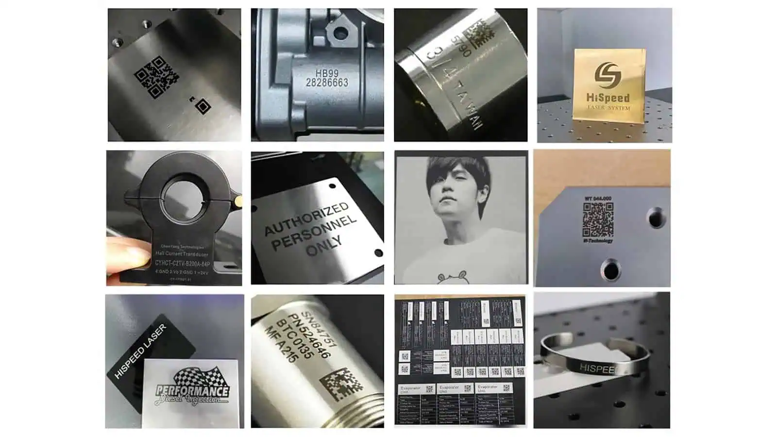
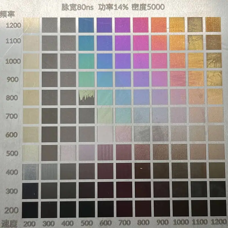
Fiber, MOPA, Green and UV Are Different Starting Routes, Not Material Shortcuts
The laser source should follow the metal, surface system, required result and acceptance window. Q-switched fiber and MOPA are both fiber-laser routes; Green and UV are alternative wavelengths that can be evaluated when a specific surface response or thermal requirement justifies them.
Fiber laser
A common starting point for many bare-metal marking, etching and engraving tasks. Final suitability still depends on alloy, finish, mark depth and cycle target.
MOPA fiber
Still a fiber-laser route, with more pulse-control flexibility than a conventional fixed-pulse approach. It can be useful when heat input, surface response or contrast needs a wider parameter window.
Green laser
Can be evaluated for selected highly reflective metal surfaces, including copper-related tasks, when near-infrared coupling or heat behavior makes the fiber route difficult. Sample testing remains necessary.
UV laser
Can be evaluated for fine features, low-heat surface interaction or specific coatings and finished surfaces. It is not the default answer for general deep metal engraving.
Do not choose by wavelength alone: laser power, pulse behavior, spot size, focus, scan strategy and the real surface condition all influence the usable process window.
Metal Variables That Change the Process Window
Before choosing a metal marking setup, define the real substrate and the acceptance test. A visible mark is not automatically a production-approved mark.
| Variable | What to check | Why it matters |
|---|---|---|
| Alloy family | Stainless steel, aluminum, carbon steel, brass, copper, titanium, gold, silver, nickel alloy | Absorption, thermal behavior and oxidation response differ. |
| Surface state | Polished, brushed, oxidized, passivated, scaled, oily or rough | Contrast and edge quality can change before the base alloy changes. |
| Coating or plating | Anodized, painted, powder-coated, plated or galvanized | The surface layer may be the real marking target. |
| Target result | Dark mark, readable code, logo, shallow etch, measured depth, coating removal | Each target needs a different process window and acceptance check. |
| Durability exposure | Abrasion, cleaning, heat, corrosion, outdoor exposure or downstream coating | The mark must survive the customer’s real process, not only a photo review. |
| Part geometry | Flat, cylindrical, curved, heavy, tiny or hard to fixture | Configuration may require fixture, rotary, 3D focus or vision support. |
Compare Material Response, Then Validate the Final Production Surface
Representative samples are useful for understanding how different metal families respond, but they are not a controlled same-source comparison unless the test conditions are documented. Final approval should use the production alloy, final surface state and the customer’s acceptance criteria.

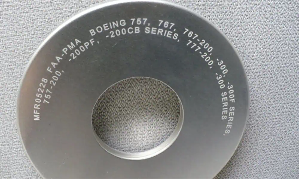
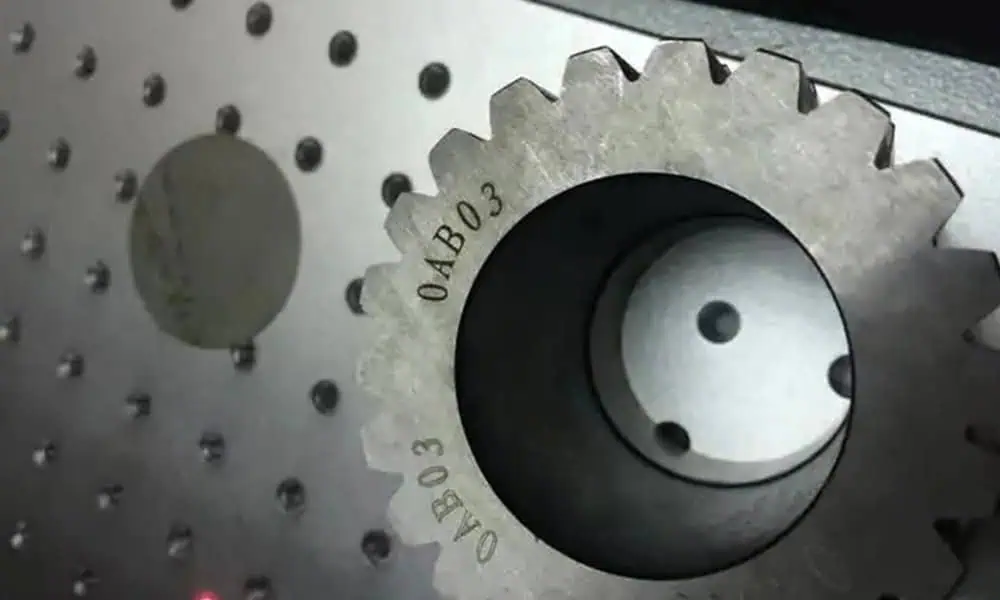
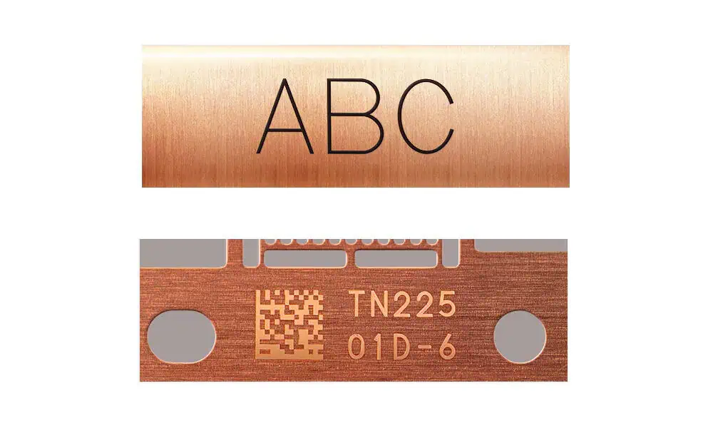
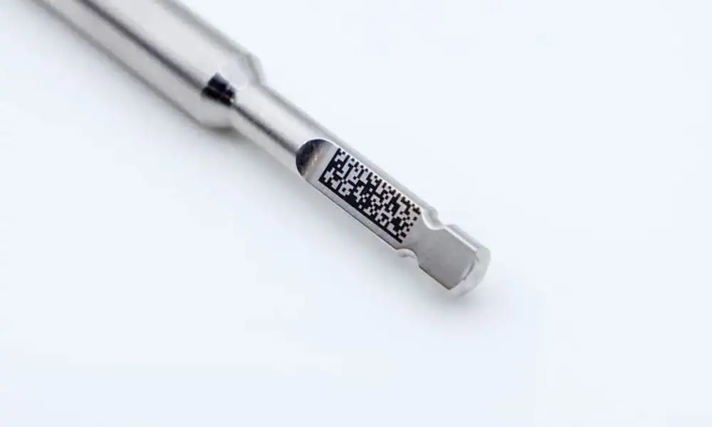
These images are representative material examples. They should not be interpreted as proof that identical laser settings, source type or process parameters were used across the samples.
Metal Sample-Test Acceptance Matrix
Approve the result with production-grade samples. A coupon with a different finish, coating or heat treatment can produce a misleading recommendation.
Test the final surface, not a convenient substitute
Send the actual alloy and surface condition when possible. If the production part is coated, plated, polished, passivated or heat treated, the sample should match that condition.
| Input | What to define | Acceptance check |
|---|---|---|
| Contrast | Visual target and machine-vision readability | Inspect under agreed lighting and reader settings. |
| Depth / profile | Minimum or maximum material removal | Measure with suitable metrology when depth matters. |
| Heat effect | Discoloration, distortion or metallurgical change | Compare against cosmetic and functional limits. |
| Durability | Abrasion, cleaning, corrosion or process exposure | Use the customer’s real downstream conditions. |
| Geometry | Focus across flat, cylindrical or irregular surfaces | Confirm fixture, rotary or 3D compensation needs. |
| Cycle | Mark time plus loading, focusing and verification | Approve full cycle rather than scan time alone. |
Account for Reflection, Fumes and the Final Machine Enclosure
Metal marking can involve hazardous laser radiation, reflected energy and fumes or particulate from coatings, oils, plating or removed material. Safety controls should be reviewed for the actual wavelength, workpiece geometry and process.
Reflection risk
Polished, curved or highly reflective parts can redirect energy. Beam paths, workpiece orientation and enclosure strategy should be reviewed before production.
Fume and particulate
Paint, plating, galvanized layers, oils and deeper engraving can create particulate or fumes. Extraction and filtration should follow the actual material and SDS.
Complete-system safety
An enclosed machine is not automatically a verified final safety class. Interlocks, access, emergency stop and the complete process cell still require review.
Choose the Machine Configuration After the Material Route Is Proven
Once the material test identifies a usable process window, machine selection can address mark field, focal setup, enclosure, extraction, fixture, rotary axis, vision and code-data workflow. Higher power does not automatically improve fine contrast, heat control or total cycle time.
Compare fiber laser marking machines when the validated route is fiber-based. Use Solutions when the part needs rotary handling, vision positioning, conveyor marking or data integration.
Information to send for recommendation
Final alloy, surface finish, coating or treatment, artwork or code, target contrast or depth, mark position, production quantity, cycle target, durability requirement and any SDS or safety constraints.
Send Metal Marking DetailsMetal Laser Marking FAQs
What laser is commonly used for marking metal?
Fiber and MOPA fiber are common starting points for many metals. Green or UV may be evaluated when a specific reflective surface, heat limit, fine feature or coating response makes another wavelength more appropriate.
Can one laser mark different metals?
Often yes, but the usable settings and even the preferred process mechanism can change with alloy, finish, coating and the required result. A machine that can create a visible mark on several metals does not guarantee the same contrast, depth, durability or cycle time on all of them.
Does anodized, coated or plated metal need a different process?
Often it does because the surface layer may become the real marking target. The process may need to modify or remove that layer without unacceptable damage to the base metal.
Is fiber laser suitable for copper and brass?
Fiber and MOPA fiber can be evaluated for copper and brass, but reflectivity, thermal conductivity, oxidation and the required effect can narrow the process window. Green or UV may also be considered for specific tasks, so sample testing is important.
Can a laser make black marks on metal without deep engraving?
Dark or black marks can be produced on selected metals and surface conditions through controlled surface response rather than deep material removal. The exact mechanism and durability should be verified on the production alloy.
Why should the final production surface be sample-tested?
Polishing, passivation, anodizing, plating, coating, oxidation and heat treatment can change how the surface responds. Testing a convenient substitute can therefore produce the wrong machine or parameter recommendation.
Send the Actual Metal, Surface Finish and Mark Requirement
Include the final substrate or coated part, alloy or grade if known, surface treatment, artwork or code, target contrast or depth, mark position, cycle requirement, durability criteria and any SDS or safety constraints. Zhuorui Laser can use these inputs to narrow the material route and define the next sample-test or machine-configuration step.
Request a Quote Ask about Material Compatibility