
Material feasibility and risk guide
Stone, Composites & Special Materials
These substrates cannot be selected from a broad material label alone. Mineral structure, resin or binder, reinforcement, fillers, coatings, density, surface finish and the required mark can change the feasible laser route, particle and fume risk, and acceptable process window.
Quick answer
Can Stone, Composites & Special Materials Be Laser Marked?
Yes—many stone, carbon-fiber and fiberglass composites, foam/EVA and rubberized surfaces can produce useful laser marks. The important limitation is that compatibility cannot be decided from the broad material name alone. Mineral structure, resin or binder, reinforcement, additives, coatings, density, color and finish can change both the achievable result and the failure mode.
Start by identifying every layer the beam reaches, define the required mark and unacceptable damage, then test the representative part. A search phrase such as “fiber laser marking machine for stone” is a buying query, not proof that fiber is the correct source; the observed material response and acceptance criteria decide the route.
Material families
Choose the Route That Matches the Actual Substrate
Stone, carbon-fiber composite, fiberglass, foam/EVA and rubberized coatings respond differently because the exposed mineral, resin, reinforcement, cell structure or coating controls the interaction. Use the closest material family as the starting point, then test the exact part.

Stone and Slate
Screen mineral composition, porosity, color, polish, natural variation and the intended surface effect. Ablation, whitening, micro-fracture, edge breakout and mineral dust belong to the stone-specific evaluation.
Review stone and slate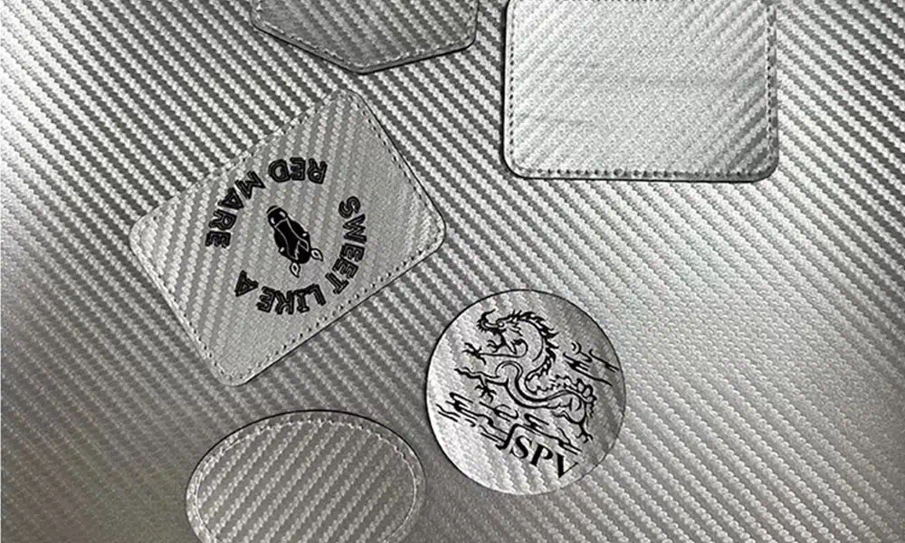
Carbon-Fiber Composite
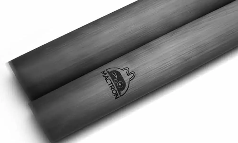
Separate the resin matrix from the carbon reinforcement. The process can remove or discolor resin, expose fibers and create fumes or particulates; the exact laminate and finish govern the test.
Review carbon-fiber composite
Fiberglass Composite
Identify resin, glass reinforcement, gel coat, paint and laminate schedule. Contrast, dust, fiber exposure and heat effects require a material-specific acceptance plan.
Review fiberglass composite
Foam and EVA
Density, cell structure, color, additives and adhesive layers can change melting, collapse, odor, edge definition and residue. Test the final foam construction, not only a resin name.
Review foam and EVARubberized Coating
Soft-touch and rubberized surfaces may be thin coatings over a different base material. Coating chemistry, adhesion, cure, thickness and decomposition products define the route.
Review rubberized coatingProducts, purposes and marking content
Where Are Special Materials Used, and What Is Usually Marked?
The end use tells you what the mark must do. A decorative logo, a serial number and a machine-readable code can be placed on the same material family, but they do not require the same feature size, contrast, durability or verification method.
Stone and Slate
Plaques, tiles, architectural pieces, memorial products and decorative stone commonly use names, logos, graphics, asset IDs or simple codes where the surface supports reliable readability.
Carbon-Fiber Composite
Sporting goods, automotive parts, drones, structural panels and composite housings may need part IDs, serial numbers, branding, assembly references or traceability marks.
Fiberglass Composite
Molded covers, panels, electrical housings and structural parts may carry part numbers, batch or serial IDs, functional information and production traceability.
Foam and EVA
Protective inserts, gaskets, pads, footwear components and organizers may use location labels, logos, part identification, alignment marks or packaging-control information.
Rubberized Surfaces
Grips, housings, controls and coated parts may need icons, logos, serials or functional identifiers while preserving the coating feel and adhesion.
Define success before testing
What Marking Result Should You Target?
A useful laser result has two parts: the physical change created on the surface and the acceptance result required in production. Define both before comparing laser sources, otherwise a visually obvious mark can still be rejected for damage, poor readability or weak durability.
1. Physical Marking Effect
Describe what the laser should physically create on the finished surface.
- Darkening, whitening or another controlled contrast change.
- Shallow engraving or a defined surface texture.
- Selective coating or surface modification without unwanted substrate damage.
- Clear text, graphics or code features with the required edge definition.
2. Acceptance Result
Define how the marked part will be judged after processing.
- Required visual contrast, consistency and feature readability.
- No unacceptable cracking, delamination, fiber exposure, melt collapse or halo.
- Residue and cleaning response within the agreed limit.
- Coating adhesion, surface feel, code verification or durability retained when the application requires it.
Feasibility inputs
Six Inputs Control the First Screening Decision
These are the six inputs to record before comparing laser sources. They are presented as a screening sequence rather than another card grid because each item feeds the next decision.
Material Identity
Trade name plus exact stone, polymer, resin, rubber or foam specification, supplier and batch when available.
Layer Construction
Reinforcement, binder, gel coat, paint, adhesive, skin, liner or backing that the beam can reach.
Surface State
Color, polish, texture, porosity, cure, contamination, moisture and prior treatment.
Target Result
Define the physical effect and the production acceptance result; use the previous section for the detailed acceptance criteria.
Risk Boundary
Heat damage, melting, collapse, fracture, exposed fibers, dust, fumes, residue and ignition potential.
Acceptance Method
Visual limits, code readability, adhesion, cleaning, wear, handling and batch consistency.
Part geometry and handling
How Do Part Shape, Thickness and Size Change the Process?
The material can be laser-compatible on a flat coupon and still become difficult on the real part. Height variation, edge distance, flexibility, thickness and marking area affect focus, heat flow, fixturing and the machine structure needed for repeatable production.
| Part condition | Why it changes the process | What to confirm |
|---|---|---|
| Flat, rigid surface | Usually provides the simplest focus and fixturing condition, but natural texture or surface variation can still change local contrast. | Marking area, flatness, repeatable datum and usable focus window. |
| Curved or irregular surface | Different points can move outside the acceptable focal range, changing spot size, energy density and mark uniformity. | Height variation, curvature, marking angle and whether rotation, repositioning or dynamic focus should be evaluated. |
| Thin or heat-sensitive section | Low thermal mass can increase distortion, melting, local collapse or backside effects before the desired mark is reached. | Minimum thickness, support method, protected backside and acceptable heat-affected zone. |
| Stone near edges, holes or natural cracks | Local stress concentration and mineral variation can increase chipping, breakout or fracture risk. | Edge distance, pre-existing defects, thickness and whether the marked zone is structurally sensitive. |
| Flexible or compressible foam / elastomer | Clamping can change surface height or shape, so inconsistent compression can create inconsistent focus and mark geometry. | Support surface, clamping pressure, part recovery and repeatable presentation to the laser. |
| Large part or large marking field | A larger usable area can change lens choice, field distortion, focus uniformity, part access and whether the part must be indexed or moved. | Overall dimensions, mark position, required field size, loading clearance and motion strategy. |
Material-led first test
Which Laser Route Should Be Tested First?
Start with the material family, the exposed layer and the required effect—not with a machine keyword. The first route is the source family most likely to create the target mark on the exposed constituent while keeping heat, fracture, fiber exposure or melt damage inside the acceptance limit. Use the sequence below to decide what enters the first comparison, then change route when the observed failure mode says the process window is too narrow.
| Material family | First route to consider | Why it enters early | When to compare another route |
|---|---|---|---|
| Stone / slate | CO2 commonly enters the first comparison for surface engraving or visible contrast on many mineral surfaces. | Long-wave interaction can produce a useful visible surface change on selected stone without assuming the stone behaves like a metal. | If contrast is weak, fracture or grain breakout is excessive, or the feature requirement is too fine, compare another confirmed source against the exact stone. |
| Carbon-fiber composite | Start from the exposed resin, coating or finished surface rather than assuming the carbon reinforcement selects the laser. | UV or CO2 may enter early on resin-rich surfaces; fiber/MOPA should enter only when near-infrared coupling produces acceptable contrast without unacceptable resin recession or fiber exposure. | Change route when the matrix is damaged before the mark is acceptable, fibers become exposed, or contrast cannot be stabilized across the laminate finish. |
| Fiberglass composite | Test the gel coat, resin or colored surface layer first; UV or CO2 often belong in the early comparison. | The visible surface usually governs the first interaction more directly than the glass reinforcement underneath. | Compare another route if the surface chars, discolors, exposes fibers, loses adhesion or cannot hold the required feature quality. |
| Foam / EVA | CO2 often enters the first comparison; UV becomes important when finer features or lower visible heat impact are needed. | Many cellular polymers respond strongly to longer-wave energy, while UV can be useful where thermal collapse or edge definition becomes the limiting factor. | Change route when melting, collapse, odor, residue or insufficient contrast prevents an acceptable window. Fiber/MOPA should only enter where pigment or additives provide useful near-infrared response. |
| Rubberized coating | Start with the coating chemistry; CO2 or UV commonly enter the first comparison for organic soft-touch layers. | The coating may be much thinner and chemically different from the substrate underneath, so the first goal is to modify the coating without losing adhesion or exposing the base part. | Compare another route when the coating smears, chars, peels, becomes tacky or the required contrast cannot be achieved without substrate damage. |
CO2: useful to compare on many mineral, foam and resin-rich surfaces, but heat, charring, melting and fracture can narrow the process window.
UV: useful when fine features or lower visible heat impact matter, but it is not automatically “cold” and still depends on chemistry and surface response.
Fiber / MOPA: only enters when the exposed surface, pigment, coating or filler responds usefully to near-infrared energy; the word “fiber” in a search query is not evidence of compatibility.
Risk map
Special Materials Fail in Different Ways
Increasing power without diagnosing the material stack can enlarge the damaged zone while reducing evidence quality. Inspect the failure mode first.
Fracture and Grain Breakout
Stone and slate can chip, whiten unevenly or follow natural mineral variation.
Matrix Removal and Fiber Exposure
Composite resin can recede before reinforcement, changing appearance and surface integrity.
Melt, Collapse and Edge Rollover
Foam and elastomeric layers can soften, shrink, collapse or leave tacky residue.
Dust, Fumes and Deposits
Mineral particles, resin decomposition products and unknown additives require SDS-led extraction and filtration review.
False Positive From One Sample
A clean mark on one coupon does not approve another batch, finish, supplier or laminate schedule.
Laser and cell safety boundary
Material Hazard Screening Does Not Replace Laser Cell Safety
Material fumes and particles are only one part of the risk review. The final machine and workcell must also control laser radiation, unintended beam paths, access and abnormal stops for the confirmed source and process.
Carry Material Hazards Into the Cell Design
Dust, fumes, deposits, fiber exposure and ignition risk found during testing should drive extraction, filtration, cleaning and enclosure decisions.
Review the Complete Laser Workcell
The final configuration must also control radiation, beam paths, guarded access, interlocks, emergency stop behavior and safe access for the actual source, fixture and automation level.
Sample validation
How Should a Real Sample Be Tested and Evaluated?
The test sequence and the returned evidence should be read together. A useful sample program records what went in, what was changed, what failed, what passed and what still has to be confirmed on the production part.
Test sequence
Identify
Use final-grade material, supplier details, layer construction, finish, geometry and SDS.
Define
Provide artwork, code, feature size, target effect, acceptance limits and protected zones.
Compare
Compare controlled source and parameter windows instead of approving a single isolated mark.
Verify
Check appearance, debris, fracture, fiber exposure, cleaning, code readability and required durability.
Transfer
Repeat on representative parts or batches, then carry the accepted window into fixture, extraction, focus and cycle review.
From sample result to machine specification
How Is the Final Laser Marking Machine Configuration Chosen?
The successful material test defines a process direction, not the complete machine. The configuration is built in sequence around the approved result, the real part and the production requirement.
Laser Source and Power Class
Start from the accepted sample route, then size practical power and pulse capability around the working process window rather than assuming higher power is automatically better.
Lens, Field and Working Distance
Mark size, feature size, part access and focus variation determine the optical setup. A larger field can trade away spot size and process margin.
Part Presentation and Focus
Translate the real geometry into height control, rotation, repositioning, indexing or a simple fixed setup, then define a fixture that presents the part repeatably.
Extraction and Safety
Dust, fumes, deposits and ignition risk found during testing determine extraction, filtration, enclosure openings, interlocks and safe access requirements.
Cycle, Vision and Automation
Loading time, throughput, variable position, code verification, data connection and line integration determine whether vision, I/O, motion or automation adds real value.
Prepare the production review
What Should You Send for a Sample Test and Quote?
The more closely the test input matches the production part, the less uncertainty remains when the machine is configured.
- Representative final-grade samples and material or supplier designation.
- Layer construction, coating, adhesive, reinforcement, SDS and surface finish where applicable.
- Part dimensions, thickness, shape, marking position and photos or drawings.
- Artwork, text, code type, minimum feature size and required marking area.
- Target contrast, texture or depth plus protected zones and unacceptable damage.
- Durability or readability checks, expected throughput, loading method and extraction constraints.
FAQ
Special Material Laser Marking Questions
Can a laser marking machine mark stone?
Selected stone and slate surfaces can be screened for laser-created contrast or texture, but mineral composition, color, polish, porosity and fracture behavior vary. The exact stone and target effect need sample testing.
Is a fiber laser the default choice for stone?
No. Search demand for a fiber laser marking machine for stone does not establish technical compatibility. CO2, UV, fiber/MOPA or another confirmed source may enter a comparison only when the material response and target justify it.
Can carbon fiber or fiberglass be laser marked safely?
A feasibility trial must separate resin behavior from reinforcement behavior and review fumes, particles, fiber exposure and the SDS. Safety and surface acceptance depend on the exact laminate, coating and process.
Why are foam and EVA grouped as special materials?
Density, cell structure, additives, pigments, adhesive layers and heat sensitivity can change melting, collapse, odor, residue and edge definition. A broad resin label does not provide enough information.
Can one successful coupon define the production setup?
No. A coupon can confirm material response, but the production part can add curvature, height variation, edge risk, clamping limits, larger marking fields, extraction requirements and cycle-time constraints. The final configuration should be checked on the representative part.
What should I send for a useful sample test?
Send representative final-grade parts or material, supplier or material designation, layer construction, SDS when relevant, part dimensions, artwork, target mark, protected zones, readability or durability requirements and the expected production cycle.
Prepare a useful review
Send the Exact Material, Part Geometry and Acceptance Target
Include representative samples, supplier/material designation, SDS, coatings or adhesives, part dimensions and thickness, photos or drawings, artwork, mark position and area, code or feature size, target effect, protected zones, durability or readability checks, loading method, cycle target and extraction constraints.