
Material response · thermal boundary
Foam and EVA Laser Marking
Foam and EVA can be laser marked, but there is no universal foam recipe. Polymer family, density, cell structure, color, additives, skin, adhesive and compression determine whether a useful process window can create readable contrast without unacceptable melting, collapse, odor, residue or edge damage.
Protect the edge and the cell structure
Engineering diagram for material discussion, not a tested Foam/EVA result.
Direct answer
Can Foam and EVA Be Laser Marked?
Yes, many foam and EVA constructions can be evaluated for laser marking. The useful question is not simply whether the laser changes the surface, but whether it can create the required identification or visual result while keeping melt, cell collapse, odor, residue and dimensional change inside an acceptable limit.
Readable without unacceptable material damage
A successful mark should remain legible under the intended inspection conditions while the surrounding foam keeps the required surface, flexibility, edge condition and compression behavior.
“Foam” and “EVA” are not complete process specifications
EVA, PE, PU and blended foams can respond differently, and even the same nominal foam can change when pigment, density, thickness, skin, adhesive, coating or compression changes.
Material variables
What Determines Laser Marking Results on Foam and EVA?
Two products both called “EVA foam” can respond differently when density, pigment, skin, adhesive or compression changes. Record the finished construction before comparing laser routes.
Polymer and additives
PU, PE, EVA and blended formulations may have different absorption, softening behavior, filler response, plume and residue. Pigment and flame-retardant packages can shift the usable threshold.
Density and cell structure
Cell size, open or closed structure, thickness and local density affect heat spreading, collapse, shrinkage and the visual edge of a mark.
Skin, adhesive and coating
Laminated skins, pressure-sensitive adhesive, print, fabric and coatings add layers. A mark that looks acceptable on the top layer may expose or disturb the layer below.
Color, contamination and compression
Color can change laser coupling; oils, dust and release agents can change local response; clamping or vacuum can alter thickness and recovery after marking.
| Variable | What may change | Failure signal | Test control |
|---|---|---|---|
| Polymer, pigment or additive package | Absorption, melt threshold, plume and residue | Low contrast, scorching, tackiness or unexpected odor | Separate formulations and colors; record supplier and batch where available. |
| Density, cell size and thickness | Heat spread, collapse, shrinkage and edge geometry | Rollover, sink, uneven depth or dimensional change | Use production thickness and representative density groups. |
| Skin, adhesive or printed layer | Layer coupling and stopping behavior | Peel, exposed adhesive, residue, delamination or false contrast | Test the final laminated construction, not a bare foam coupon. |
| Compression, contamination or surface finish | Local focus and energy coupling | Patchy mark, position drift or recovery change | Use the real fixture condition and the agreed cleaning method. |
Application context
Where Are Foam and EVA Parts Used and Why Are They Marked?
Foam and EVA appear in products where cushioning, sealing, spacing, insulation, grip, fit or flexible protection matters. The application changes what the mark is allowed to do to the surface, edge, adhesive layer and compression behavior.
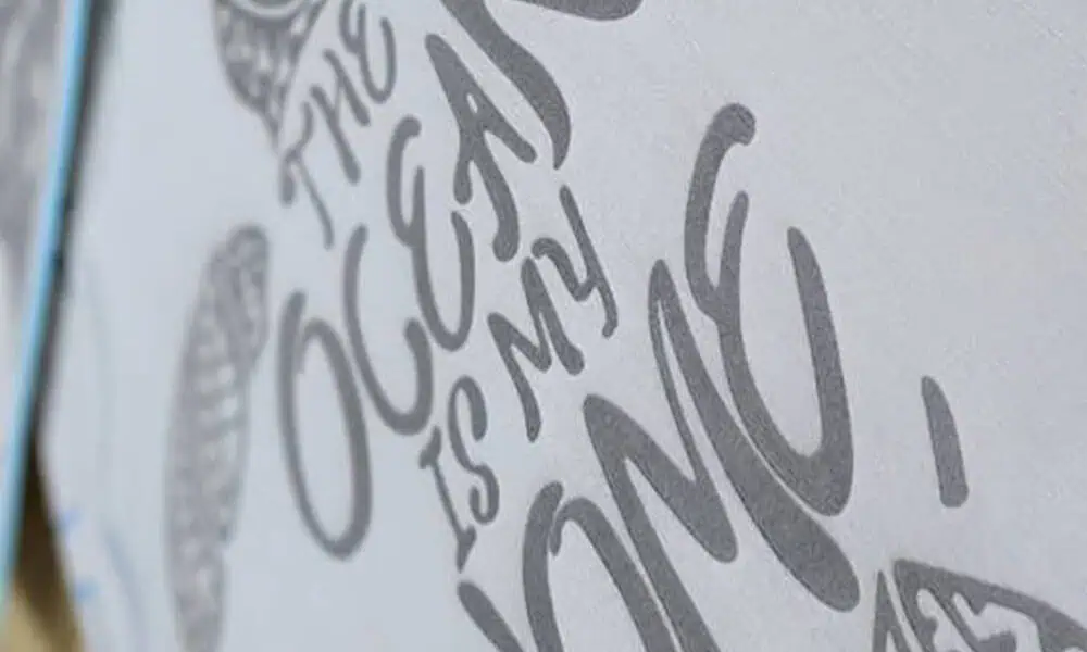
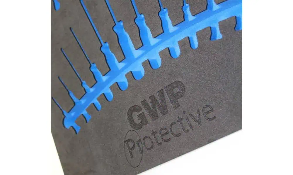
| Part context | Why it may be marked | What the process must protect |
|---|---|---|
| Protective packaging, inserts and cushioning components | Part identification, orientation, branding, lot or handling information | Fit, clean surface condition, low loose residue and acceptable odor |
| Gaskets, pads, seals and die-cut foam parts | Part number, batch, assembly identification or orientation | Edge geometry, dimensions, compression response and functional contact areas |
| Footwear, insoles and molded EVA components | Size/model identification, alignment marks, symbols or branding | Appearance, flexibility, local cell structure and surface feel |
| Insulation, spacing and assembly-support foam | Identification, orientation, traceability or installation guidance | Dimensions, adhesive/backing condition and downstream assembly function |
Marking content
What Is Usually Marked on Foam and EVA Parts?
The artwork matters because a large logo, a small symbol and a machine-readable code do not require the same feature size, edge definition or contrast stability.
- Part numbers, model identifiers and size information
- Batch, lot or serial information where the process window supports repeatable readability
- Logos, symbols and simple graphics
- Alignment, orientation or assembly marks
- Barcodes or 2D codes only after the actual surface and reader method are validated
Artwork rule: define the smallest character, line, gap or code cell before selecting optics and process settings. A mark can look acceptable at large scale while losing detail at production feature size.
| Content | Main process concern | What to verify |
|---|---|---|
| Large text or logo | Uniform contrast and broad-area heat load | Color consistency, halo, gloss change and surface collapse |
| Small text or fine symbols | Edge definition and feature loss | Minimum readable feature and repeatability across the part |
| 1D / 2D codes | Cell or bar definition on a soft or textured surface | Actual reader/verifier performance under the intended inspection setup |
| Alignment or assembly marks | Position accuracy relative to part features | Fixture repeatability, compression and mark-location tolerance |
Target result
What Marking Result Should You Target on Foam and EVA?
For a marking project, define the acceptable visual and surface result before comparing machines. The target should describe what must remain readable and what material change is still acceptable.
Readable surface contrast
The goal is a visible mark with enough contrast for the intended inspection method while keeping the surrounding foam stable. Review local gloss, melt halo, cell collapse, tackiness, odor and residue together with readability.
Shallow surface modification with controlled detail
Some projects can accept limited surface recession or texture change if the mark remains clean and the foam does not sink, char, expose adhesive or lose the required feature definition.
Scope note: perforation and through-cutting are related laser-processing tasks, but they use a different acceptance window from surface marking. Treat them as separate requirements when they are part of the project.
Part geometry
How Do Part Shape, Thickness and Size Change the Process?
Soft, compressible foam does not behave like a rigid flat coupon. Geometry changes focus, fixturing, local density and how consistently the tested process window can be reproduced.
Thickness and density variation
Thickness and local density can change heat spreading, surface response and the distance from the optics. Production testing should include representative thickness groups instead of one ideal coupon.
Flat, molded or curved surfaces
Height changes across a molded or curved part can push the mark away from the intended focus. Large height variation may require a different focusing or positioning strategy.
Part size and mark location
A large workpiece can change fixture access, working distance and where the mark sits within the usable field. Do not choose field size from artwork dimensions alone.
Fixture compression
Clamping, vacuum or support pressure can change foam thickness and recovery. The sample test and production fixture should use a comparable compression condition.
Conditional source screening
Which Laser Route Should Be Tested First?
CO2 is often a practical first screening direction for many polymeric foam constructions, but the final material and target mark still decide. UV may be evaluated where fine features or a different surface interaction is useful. Fiber or MOPA should remain conditional where pigment, coating, filler or an exposed layer couples with near-infrared energy.
- No wavelength should be approved from the material name or color alone.
- Spot size, pulse behavior, focus, scan strategy and field position affect the local thermal load.
- Compare a stable process window across density, thickness, color and layer variation.
- For odor-sensitive products, extraction and post-process odor checks are part of acceptance.
| Direction | Why it may enter screening | Main boundary | Approval evidence |
|---|---|---|---|
| CO2 | Often considered for polymeric foams where long-wave absorption can create a useful surface response. | Thermal spread, melt halo, shrinkage, odor, char and edge rollover can limit the usable window. | Contrast, edge condition, dimensional change, odor/extraction review and repeatability. |
| UV | May be evaluated for fine features or selected formulations where a shorter-wavelength interaction gives a useful surface response. | UV is not automatically cold; chemistry, discoloration, debris and achievable contrast remain sample-dependent. | Feature fidelity, surface integrity, residue, odor and stable window across samples. |
| Fiber / MOPA | Conditional trials where pigment, coating, filler or an exposed layer couples with near-infrared energy. | Foam may respond weakly or unevenly; local heat can still create melt, odor or collapse. | Direct evidence on the final construction and comparison against the required effect. |
Selection rule: approve the source only after the finished Foam/EVA construction meets visual, dimensional, odor and residue criteria across representative variation.
Failure map
What Are the Common Risks and Failure Modes?
Increasing local energy may make a mark darker while moving the foam into a melt, odor, collapse or residue zone. Identify the failure mode before assuming a different laser source is the answer.
Melt and cell collapse
Softening can close cells, sink the surface, create a glossy halo or change compression recovery around the mark.
Weak or uneven marking
Changes in color, density, skin, contamination or layer construction can produce patchy contrast or inconsistent feature definition across nominally similar parts.
Odor and plume
Polymer and additive chemistry can generate odor, smoke or fine particles. Extraction and SDS review belong in the configured machine assessment.
Char, residue and edge damage
Higher-energy surface modification can leave darkened edges, tacky redeposition, loose debris or exposed adhesive that fails visual or downstream assembly requirements.
Representative validation
How Should a Foam/EVA Sample Be Tested and Evaluated?
A single attractive mark on one coupon does not prove a production window. Use the final foam construction, final fixture condition and the acceptance method that production will actually use.
Freeze the marking requirement
State the target contrast or shallow surface effect, artwork, smallest feature, mark location, edge limit and allowed dimensional change.
Group the construction
Record polymer family, density, thickness, color, skin, adhesive, coating, supplier and batch where available.
Compare a process window
Hold lighting, measurement and cleaning constant while comparing source directions and a controlled parameter matrix.
Repeat under production conditions
Add compression, focus tolerance, fixture repeatability, extraction, loading and inspection before accepting the result for machine configuration.
| Record | Minimum detail | Why it matters |
|---|---|---|
| Material identity | Polymer, density, thickness, color, skin/adhesive/coating and batch | Prevents pooling different constructions under “EVA foam”. |
| Marking requirement | Surface contrast or shallow surface modification; artwork, mark size and smallest feature | Defines what the process must actually reproduce. |
| Surface and dimensions | Melt halo, cell collapse, char, residue, shrinkage and compression recovery | Separates a readable mark from a functionally acceptable part. |
| Handling durability, when relevant | If the marked area will be rubbed, compressed, cleaned or repeatedly handled, reproduce the relevant contact or compression condition after marking. | Confirms that an acceptable fresh mark remains legible and the foam surface remains functional under the actual handling condition. |
| Odor and residue | Immediate and post-rest odor check, visible plume/residue and cleaning method | Protects product, operator and downstream assembly requirements. |
| Production inputs | Fixture, compression, focus, field, loading, inspection method, data and cycle target | Turns the qualified material result into a machine specification. |
From sample to system
How Is the Final Machine Configuration Chosen?
The sample test establishes whether the material can be marked and which laser route has a stable working window. The final machine is then configured around the validated process, the real part geometry, the required marking field, extraction, loading, inspection and production target.
| Validated input | What it affects | Configuration question |
|---|---|---|
| Stable laser route and process window | Source family and available operating margin | Which source family and control range reproduce the accepted mark without pushing the foam into melt or collapse? |
| Mark size and smallest feature | Optics, field size and feature capability | What marking field and optical setup preserve the required detail across the working area? |
| Part thickness, shape and height variation | Focus adjustment, Z travel and fixture strategy | How will the system keep the marked surface inside the qualified focus range? |
| Softness and compression behavior | Fixture, support and loading method | How will the part be held without changing the material response seen during testing? |
| Odor, smoke and residue level | Enclosure, extraction and filtration review | What capture and maintenance arrangement is required for the actual formulation and process? |
| Production quantity and cycle target | Manual loading, multi-position fixtures or automation review | What handling method meets throughput without sacrificing positioning and repeatability? |
| Variable data, codes or inspection requirement | Software, data input, vision or verification options | Does the project need variable data handling, positioning assistance or reader/verifier integration? |
For an RFQ: send the finished Foam/EVA part, material/density/thickness information, layers, artwork, smallest feature, required mark result, allowable edge/odor/residue limits, part dimensions, fixture condition, sample quantity and cycle-time target. These inputs let the sample result be translated into a machine configuration instead of a generic power recommendation.
Frequently asked questions
Foam and EVA Laser Marking FAQs
Can EVA foam be laser marked?
It can be evaluated, but “EVA” is not a complete process specification. Density, cell structure, pigment, additives, thickness, skin and adhesive layers can change melting, odor, edge and contrast. Use the final construction for a sample test.
Will laser marking melt foam?
It can if the local thermal load exceeds the material window. Melt halo, cell collapse, shrinkage and gloss change should be inspected alongside readability; the best-looking single mark is not automatically acceptable.
Which laser is best for foam?
CO2 is often a first screening direction for many polymeric foams, while UV or fiber/MOPA may be evaluated for specific formulations, fine features or surface layers. The final construction and target result decide.
How do I control odor from foam laser processing?
Review the formulation and SDS where available, capture plume at the mark, define filtration and cleaning, and include immediate and post-rest odor checks in acceptance. Odor control is part of the configured system, not only the laser source.
Should I send raw foam or the finished part for testing?
Send the production-finished construction whenever possible. Skin, print, adhesive, backing, compression and surface contamination can change the response, so a bare foam coupon may not represent the final part.
What should I send for a Foam/EVA sample test?
Send production-finished samples, polymer/density/thickness information, color, skin or adhesive details, target result, artwork, smallest feature, edge and odor limits, fixture condition and any downstream cleaning or assembly requirements.
Next step
Send the Finished Foam Part, Marking Content and Acceptance Criteria
Share the Foam/EVA construction, density, thickness, layers, part dimensions, artwork, smallest feature, target mark result, odor and edge limits, fixture condition, inspection method and cycle target. Zhuorui Laser can use those inputs to define the sample test and then recommend the machine configuration that matches the validated process.
Request a Quote OEM & Custom Inquiry Contact Us