
Technical knowledge hub
Laser Marking Resources
Use this engineering library to understand laser marking technology, compare process routes, plan machine configuration, prepare files, manage safety, troubleshoot equipment, and define a result that can be tested on the real part.
- Eight permanent knowledge tracks
- Selection and troubleshooting logic
- Sample-test boundaries kept explicit
Start with the decision
Use laser marking resources to reduce the right uncertainty
A useful technical resource should help you make a better decision, not simply introduce more terminology. Begin with the question that is blocking your project and follow the matching knowledge track.
- 01Learn the mechanism
Use technology guides when wavelength, pulse behavior, optics, or scanning is the part you do not yet understand.
- 02Compare credible routes
Use comparison guides when two laser technologies or marking processes could plausibly meet the same task.
- 03Turn a goal into a configuration
Use configuration and file-preparation resources when the technology direction is known but the working setup is not.
- 04Control risk and repeat the result
Use safety, maintenance, troubleshooting, and result guides when the system must operate reliably beyond the first sample.
Resource library
Eight laser marking knowledge tracks
Each track owns a distinct technical task. Choose the one that matches your current decision rather than reading every topic in sequence.
Laser Technology Guides
Understand laser sources, wavelengths, pulse behavior, spot formation, field lenses, and galvo scanning at the level needed for equipment decisions.
Use when: you need to understand why a source or optical system changes the result.
Open technology guidesComparison Guides
Compare plausible laser routes and alternative marking processes through material fit, heat input, detail, maintenance, operating constraints, and validation needs.
Use when: two technologies appear capable but the trade-offs are unclear.
Compare laser marking routesPower, Field Size & Configuration
Relate average power, pulse behavior, frequency, field size, spot size, lens choice, machine format, cooling, and options to the actual job.
Use when: the technology is known but the configuration still needs to be narrowed.
Plan machine configurationSafety & Compliance
Review laser classes, guarding, interlocks, emergency stops, extraction, hazardous materials, maintenance states, and market-specific compliance boundaries.
Use when: machine format or installation decisions depend on risk control.
Review safety resourcesSoftware & File Preparation
Prepare vector artwork, fonts, barcodes, variable data, layers, serial content, and production files before parameter testing begins.
Use when: the artwork or data path may limit mark quality or production repeatability.
Prepare files and dataMaintenance & Troubleshooting
Trace common faults through symptoms, likely causes, safe checks, optics and focus, cooling, extraction, connections, and escalation boundaries.
Use when: a previously working process becomes unstable, weak, inconsistent, or unavailable.
Troubleshoot marking systemsChecklists, Calculators & Downloads
Use practical worksheets for RFQ preparation, sample review, maintenance planning, acceptance criteria, and configuration conversations.
Use when: you need a repeatable tool rather than another explanatory article.
Find tools and downloadsLaser Marking Methods & Results
Distinguish marking, engraving, etching, annealing, ablation, foaming, carbonization, coating removal, coding, and other result mechanisms.
Use when: the required appearance or material change has not been defined precisely.
Explore methods and resultsDecision path
A practical laser marking evaluation sequence
The sequence matters because every later choice depends on earlier inputs. A machine recommendation made before the material, result, geometry, and workflow are defined is incomplete.
Material and surface
Record the exact substrate, grade or formulation, color, coating, oxide, plating, finish, contamination, and allowable surface change.
Required marking result
Define contrast, color, depth, tactile change, coating removal, code readability, durability, and any prohibited damage.
Laser and optical route
Compare wavelength, pulse behavior, spot size, field lens, focus tolerance, scanning strategy, and the need for sample testing.
Geometry and positioning
Confirm part size, marking area, flat or curved surfaces, access, fixture repeatability, rotary motion, vision, and working distance.
Production system
Include loading, positioning, marking, verification, unloading, reject handling, data exchange, extraction, guarding, and maintenance access.
Acceptance and evidence
Agree on how the result will be judged on real samples, including visual criteria, code verification, durability, variation, and cycle-time scope.
Why system context matters
Laser source choice is only one part of the marking system
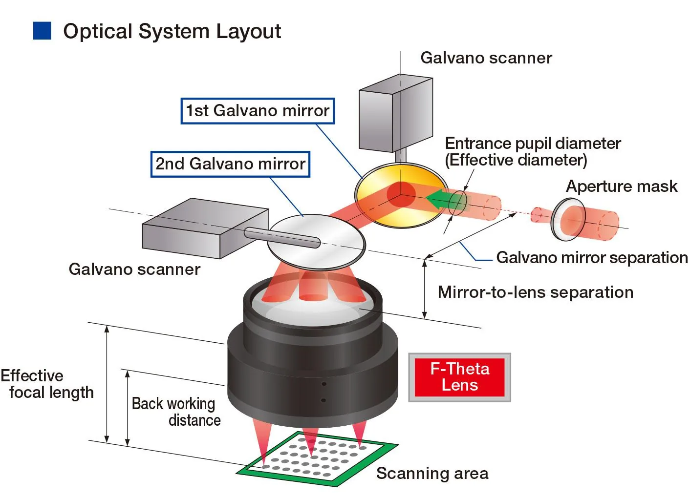
Optics change the usable result
Field size, focal length, beam delivery, spot behavior, and focus tolerance can change detail and energy density even when the laser source is unchanged.
Motion changes the problem
Rotary, XY, 3D dynamic focus, vision, and conveyor motion introduce positioning, calibration, synchronization, and acceptance questions that a static flat sample does not reveal.
The complete cycle changes productivity
Laser scan time is only one component. Loading, locating, clamping, data preparation, marking, inspection, reject handling, and unloading determine the production cycle.
Continue with laser technology guides or review laser marking solutions when the task involves motion, data, vision, or automation.
Comparison snapshot
Use laser families as evaluation routes, not universal answers
The table provides a starting frame only. Material formulation, surface condition, desired result, part geometry, field, throughput, and acceptance criteria can change which route is appropriate.
| Technology route | Why it may enter the evaluation | What still needs confirmation |
|---|---|---|
| Pulsed fiber | Often evaluated for metals and selected engineered polymers where near-infrared absorption and compact galvo systems are practical. | Alloy, coating, required contrast or removal, pulse behavior, field size, heat input, and real-sample result. |
| MOPA fiber | A fiber-laser subtype considered when a wider pulse-width and frequency adjustment range may help control the process window. | The useful window for the actual material, target effect, speed, optical setup, and batch variation. |
| UV | Commonly evaluated for fine features and materials where 355 nm absorption may support a different response from near-infrared or CO2 routes. | Material formulation, discoloration, cracking or melting risk, optical path, maintenance, and acceptance result. |
| CO2 | Commonly evaluated for many organic and non-metal materials; source wavelength can vary by system and application. | Specific wavelength, material absorption, surface result, extraction, speed, field, and whether another route is more suitable. |
From research to evidence
Build a testable laser marking brief
A good brief turns general knowledge into a sample plan and gives engineering teams enough context to compare configurations without assuming a guaranteed result.
- MaterialExact grade, formulation, color, coating, finish, and safety data.
- MarkContent, smallest feature, code type, area, location, and target appearance.
- PartDimensions, weight, access, curvature, tolerances, photos, and drawings.
- ProductionVolume, takt target, loading, fixture, motion, inspection, and reject flow.
- DataSerial source, barcode rules, database, PLC, MES, and verification method.
- AcceptanceContrast, readability, depth, durability, damage limits, and sample quantity.
Decision boundaries
What this resource library cannot decide without project evidence
- Guaranteed resultAppearance, depth, color, durability, heat effect, and code performance depend on the real sample, optical setup, parameter window, and acceptance method.
- Exact configurationPower, field lens, machine format, fixture, motion, cooling, extraction, guarding, and software must be matched to the complete application.
- Laser classificationAn enclosure alone does not establish the classification of the complete machine. Accessible radiation, interlocks, operating modes, and the finished system must be evaluated.
- Regulatory complianceGeneral resources do not replace applicable standards, local regulations, risk assessment, installation acceptance, or the responsible safety and compliance professionals.
Frequently asked questions
Questions about using the laser marking resource center
Which laser marking guide should I read first?
Start with the uncertainty that blocks your next decision. Use technology guides for mechanisms, comparison guides for route selection, configuration guides for system planning, and methods-and-results guides when the required mark has not been defined precisely.
Can machine power alone determine the right configuration?
No. Power must be considered with wavelength, pulse behavior, frequency, spot size, field lens, speed, hatch, focus, material response, geometry, cycle, and the required result. A higher power number does not automatically provide a better mark or a faster complete production cycle.
Does an enclosed laser marking machine automatically qualify as Class 1?
No. Classification applies to the complete product in its specified configuration and operating modes. Enclosure design, accessible radiation, interlocks, service states, and the complete safety system must be evaluated.
Do the resources provide universal parameter settings?
No. Parameter examples are only useful when the material, surface, optical configuration, field, target result, and test conditions are known. Final settings should be established and recorded through controlled sample testing.
What should I send for a useful sample or configuration review?
Send the material specification, surface condition, part photos or drawing, marking content and dimensions, target result, production volume and cycle target, positioning needs, data requirements, destination market, and the acceptance criteria that will be used to judge the sample.
Turn your research into a marking test plan
Share the material, surface, part geometry, marking content, target result, production cycle, data needs, and acceptance method. Zhuorui can review the brief and identify what should be tested before a machine configuration is finalized.