Laser Marking Methods & Results
Understand how the laser changes a surface before you compare machines. This guide separates annealing, ablation, foaming, carbonization and deep engraving, then connects each mechanism to the result you can inspect and approve.
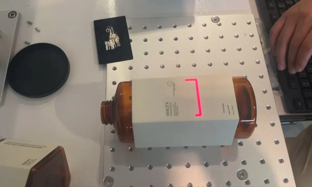
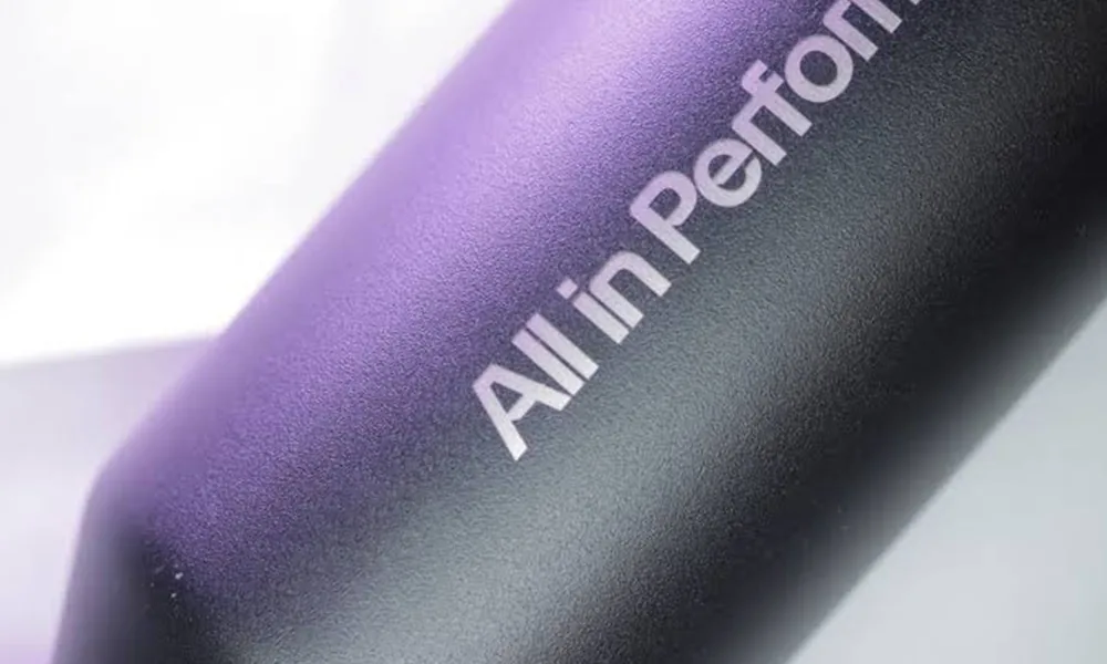

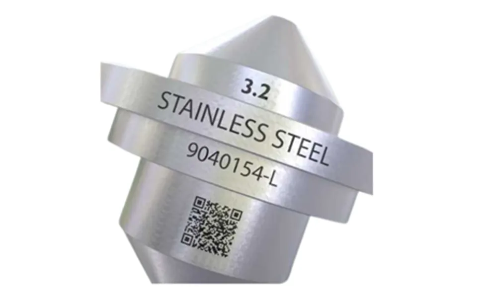
These sample images illustrate the marking categories; they do not guarantee the same result on a different material, coating or machine configuration.
Laser Marking Methods in 30 Seconds
Start with what physically changes on the workpiece. The same visible contrast can come from very different interactions, so method names should follow the required surface change and acceptance test.
Heat-driven surface oxide or colour change on suitable metals, with little or no intentional material removal.
Removes a coating or controlled surface layer to expose the intended underlying layer or substrate.
Changes suitable polymers so a lighter or raised mark can form at the surface.
Darkens suitable organic materials or polymers through a heat-driven surface change.
Deliberately removes base material to create measurable depth, relief or a recessed feature.
Define the Laser Marking Result Before Choosing a Method
A readable mark can be created by several different surface changes. Specify what must remain after cleaning, abrasion, heat or chemical exposure before discussing wattage, field size or product models.
Contrast or colour
Ask whether the target is a dark, light or colour-shifted surface with minimal material removal.
Route to result criteriaTexture or roughness
Define gloss, roughness, tactile feel, edge quality and the allowed heat-affected zone.
See comparison variablesDepth or cavity
Set depth, profile, debris, burr, dimensional and cycle-time limits when material is removed.
Open deep engraving guideCode readability
Define the reader, quiet zone, smallest feature, contrast and verification grade for variable data.
Open code guideFour Common Laser Marking Mechanisms
Mechanism names describe the physical interaction, not a universal source recommendation. Absorption, coating stack, additives, pulse behaviour, focus and heat flow all change the practical result.
Creates a controlled colour change by heating suitable metals and forming an oxide layer at the surface, with little or no intentional material removal. Inspect contrast, viewing angle, corrosion behaviour and heat impact.
Removes a coating or a controlled layer. Inspect edge definition, residue, base-material exposure and dimensional change.
Changes a polymer surface so a lighter or raised mark appears. Inspect additive response, gloss, colour, height and durability.
Darkens suitable organic or polymer surfaces. Inspect smoke residue, heat spread, contrast stability and cleaning behaviour.
First-Pass Laser Marking Method Selection
This table narrows the first test route; it does not approve a material or machine. Final suitability still depends on the real surface, geometry, source, optics, process window and acceptance criteria.
| Method | What physically changes | Typical result | Starting material direction | Main risk / limitation |
|---|---|---|---|---|
| Annealing | Heat-driven surface oxide or colour change with little intentional removal | Dark or coloured surface mark | Suitable metals, especially where surface integrity matters | Colour drift, heat effects, corrosion behaviour or inconsistent appearance |
| Ablation | A coating or controlled surface layer is removed | Exposed layer or substrate with a defined edge | Painted, coated, anodized or layered surfaces | Incomplete removal, coating lift, residue or base-material damage |
| Foaming | Local polymer response creates a lighter or raised surface | Light, raised or texture-shifted mark | Suitable plastics and polymers with a usable response window | Additive dependence, excessive texture, gloss change or durability limits |
| Carbonization | Heat-driven darkening in suitable organic or polymer surfaces | Dark mark with limited deliberate depth | Selected polymers and organic materials | Haze, residue, heat spread or contrast loss after cleaning |
| Engraving | Base material is deliberately removed | Recessed depth, relief or textured cavity | Any laser-responsive material where controlled removal is acceptable | Cycle time, debris, roughness, burr/recast where applicable, heat or distortion |
Common Laser Marking Results: Black Marks, Color and Codes
Use the detailed guide for the result you need. Each one explains the material limits, process variables and validation evidence needed before production approval.
Black and High-Contrast Laser Marking
Compare darkening routes by material, surface condition, heat input and durability test.
Explore black markingColor Laser Marking
For suitable metals such as stainless steel, MOPA fiber can provide pulse-width control for color marking. Also evaluate oxide formation, viewing angle and batch consistency.
Explore colour markingQR Codes, Data Matrix Codes & Serial Numbers
Connect contrast and feature size to reader setup, verification and traceability data.
Explore code markingHow to Compare Laser Marking Methods and Results
Keep the sample, artwork, inspection and exposure constant. Otherwise a different result may simply reflect a different test boundary.
| Decision variable | Surface change | Layer removal | Deep engraving | Code readability |
|---|---|---|---|---|
| Primary result | Contrast, colour or gloss shift | Exposed layer with defined edge | Depth, profile and texture | Stable symbol and quiet zone |
| Material / surface inputs | Alloy, finish, coating and heat limit | Coating stack and base-material tolerance | Grade, thickness, support and debris path | Material, surface or coating, reflectivity, geometry and minimum feature size |
| Inspection | Lighting, viewing angle and contrast method | Edge, residue, base damage and dimensional check | Profile/depth, roughness and cleaning check | Reader, verifier, grade and repeatability |
| Main production risk | Colour drift, heat tint or corrosion change | Incomplete removal, burr or coating lift | Slow cycle, recast, burr or distortion | Unreadable cells, low contrast or placement error |
Failure Signals: When a Laser Marking Method Is the Wrong Choice
A visually acceptable first sample can still be the wrong process route. Treat these signals as reasons to change the process window, reconsider the mechanism or run a different method comparison before release.
Annealing
Reconsider the route when: heat tint spreads outside the mark, contrast varies strongly with viewing angle, corrosion behaviour becomes unacceptable, or the approved colour cannot be repeated across the real surface condition.
Ablation
Reconsider the route when: coating remains in the cleared area, edges lift, residue redeposits, or the base material is damaged before the intended layer is cleanly exposed.
Foaming
Reconsider the route when: the mark becomes excessively raised or rough, gloss changes outside the acceptance limit, contrast varies with formulation, or the mark fails cleaning or wear checks.
Carbonization
Reconsider the route when: haze or smoke residue remains, heat spreads beyond the mark, the surface chars excessively, or contrast drops after the required cleaning process.
Engraving
Reconsider the route when: burr, recast where applicable, roughness, debris, distortion or cycle time exceed the requirement before the target depth is reached.
Average power is only one variable. Pulse behaviour, focus, spot size, scan strategy, passes, extraction, material response and the required acceptance test can all change the usable process window.
Build a Repeatable Marking Test Plan
A single sample photo is not enough for process approval. A useful test records what changed, where it changed and whether the result survives the actual downstream conditions.
Sample and material grade, surface/coating, artwork and size, required effect, cycle target, inspection method, cleaning or wear exposure, and the production fixture.
- 1
Freeze the sample
Record grade, finish, coating, colour, geometry and contamination.
- 2
Define the mark
Specify file, size, line width, depth, contrast, texture and protected zones.
- 3
Run the comparison
Hold fixture, focus, field, extraction and inspection conditions constant.
- 4
Approve the result
Repeat the test after cleaning, abrasion, heat, chemicals or sterilization as required.
Laser Marking Method and Result Guides
Open the guide that matches the engineering question you still need to resolve. Each guide goes deeper into the variables, limits and validation checks for that result.
Annealing, Ablation, Foaming & Carbonization
Mechanism definitions, material limitations and the checks that distinguish a surface change from removal.
View mechanism guideDeep Laser Engraving Guide
Depth, cycle-time, roughness, heat, debris and power trade-offs for material removal.
View engraving guideBlack & High-Contrast Laser Marking
Dark and light contrast routes by material, surface condition and durability evidence.
View contrast guideColor Laser Marking Guide
For suitable metals such as stainless steel, MOPA color marking depends on pulse control, oxide formation, viewing angle, process window and batch consistency.
View colour guideQR, Data Matrix & Serial Number Marking
Code size, contrast, variable data, verification and traceability requirements.
View code guideMicro Laser Marking & Fine Features
Spot size, field size, optics, focus and readable-feature trade-offs for small marks.
View micro-marking guideWhy Sample Images Do Not Guarantee Laser Marking Results
The sample image is for visual orientation only. Production approval should use the real material, complete mark file, source and optics, controlled test conditions, a defined inspection method and repeatable acceptance criteria.
Request a sample review
Questions About Laser Marking Methods and Results
Is laser marking the same as laser engraving?
No. Marking can change colour, contrast or texture with little removal; engraving deliberately removes material. The suitable mechanism depends on the required result and acceptance test.
Can one laser source create every marking effect?
No. Source wavelength, pulse behaviour, optics, material absorption, coating and geometry all constrain the practical process window. Use a source comparison as a test route, not an automatic answer.
Why do sample photos not prove a production result?
A photo does not capture alloy or polymer grade, surface finish, focus, field position, lighting, cleaning or durability. Those variables must be fixed in the test brief.
Where should I check machine specifications and material compatibility?
Check product pages for actual model and configuration data, material guides for substrate behaviour, and solution pages for line integration. Use this guide to compare marking methods and result trade-offs.
Turn the Desired Result into a Testable Marking Brief
Share the real sample, mark file and acceptance rules. Zhuorui Laser can then route the discussion to the appropriate source, machine configuration or automation path.