
Material family guide / surface state
Coatings & Surface Treatments Laser Marking
A coating is not a material shortcut. The laser may need to change, remove or selectively expose the surface layer while leaving the metal, plastic or electronic substrate within its acceptance limits. This guide compares anodized, painted, powder-coated, plated, oxide-treated and coated-plastic surfaces by the layer that controls the process window.
Quick answer
Can a laser mark a coated surface?
Often, yes. The useful answer depends on the coating or treatment, the substrate underneath, the target effect and the limit for exposed base material, heat, residue, appearance and durability. “Coated metal” is therefore a starting classification, not a complete process specification.
First record whether the target is color change, selective coating removal, readable contrast, a tamper-evident surface change or a clean exposed layer. Then identify the exact coating family, cure state, thickness, color, gloss and adhesion. The same laser family can behave differently when one of those variables changes.
Determine which layer absorbs the beam and which layer must remain unchanged.
Reflectivity, thermal conductivity, polymer sensitivity and exposed-base requirements change the window.
A clean photograph is not proof of adhesion, corrosion resistance, code reading or production yield.
Material routes
Choose the Surface Treatment That Controls the Decision
Choose the closest surface family first. Each route narrows the coating variables, substrate interaction, target effect and durability checks that should be confirmed on a production-representative sample.
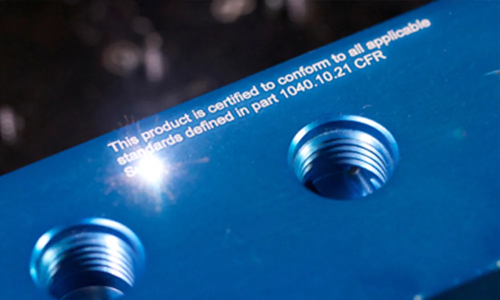
Anodized Aluminum
Evaluate oxide thickness, color, gloss, alloy, white or dark contrast, exposed-metal appearance and wear after marking.
Open anodized aluminum route
Painted Metal
Separate paint ablation from base-metal marking. Check paint chemistry, cure, edge quality, residue, corrosion exposure and surrounding adhesion.
Open painted metal route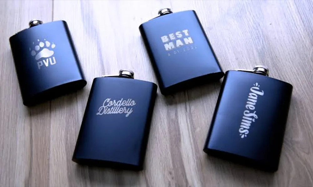
Powder-Coated Metal
Powder thickness and binder chemistry influence removal, plume, particles, undercut and the contrast of the exposed metal.
Open powder-coated route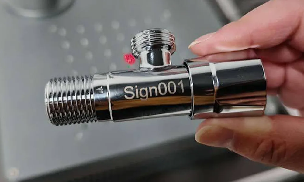
Plated Metal
Nickel, chrome, gold and multilayer plating create layer-to-layer risks. Define the permitted exposure, roughness and adhesion boundary.
Open plated-metal route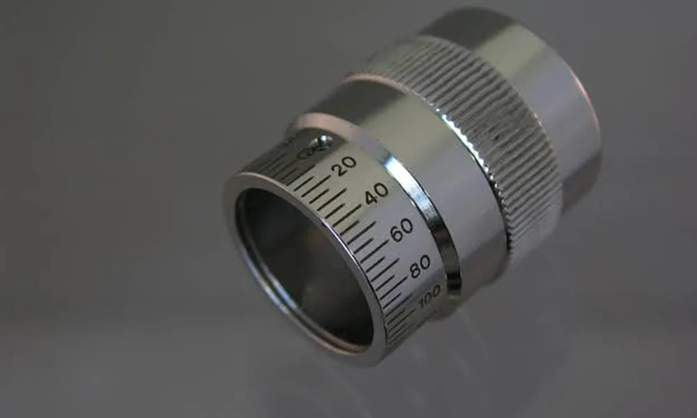
Oxide Layers
Black oxide and other oxide states can be changed or removed, but the base alloy, oxide stability and corrosion requirement remain part of approval.
Open oxide-layer route
Coated Plastics
Painted or lacquered polymer parts combine coating ablation with melting, warping, smoke and base-plastic contrast risks.
Open coated-plastic routeRepresentative coated-surface marking examples. Final appearance and process acceptance depend on the actual coating stack, substrate and test criteria.
Surface-state map
Define the Surface Stack Before Comparing Machine Power
The first useful comparison is between the surface state and the acceptance evidence. Power, scan head and field size are downstream configuration variables, not substitutes for coating identification.
| Surface state | Target result to define | Variables that move the process window | Evidence before approval |
|---|---|---|---|
| Anodized aluminum | White contrast, dark contrast, controlled oxide removal or color change | Alloy, anodic thickness, dye, gloss, reflectivity, exposed-metal appearance | Contrast uniformity, abrasion, cleaner exposure and corrosion check when required |
| Paint or powder coat | Selective ablation with a clean edge and defined stopping layer | Binder, pigment, cure, thickness, adhesion, base reflectivity and plume | Edge inspection, residue, surrounding adhesion, corrosion or solvent exposure |
| Plated surface | Surface change or controlled layer removal without damaging the next layer | Plating stack, thickness, hardness, substrate, undercut and permitted exposure | Layer boundary, roughness, adhesion, electrical or corrosion requirement |
| Oxide layer | Stable color change or repeatable removal to the alloy | Oxide chemistry, alloy, pre-cleaning, oil, passivation and environment | Color consistency, re-oxidation, cleaning, corrosion and wear test |
| Coated plastic | Coating removal or contrast without unacceptable base-plastic heat damage | Resin, pigment, coating chemistry, cure, wall thickness, texture and additives | Warping, melting, fumes, edge quality, adhesion and service exposure |
Send the complete stack: substrate grade, treatment or coating name, color, thickness if known, cure state, surface finish, cleaning history and the exact mark location. Unknown coatings should remain a test variable, not be treated as bare material.
Real-part context
Where Are Coated Parts Used and Why Are They Marked?
Coated surfaces appear on housings, panels, brackets, controls, connectors and finished components where the coating provides appearance, insulation, wear resistance, corrosion protection or a functional surface. Laser marking is typically used when identification must be permanent, precise or integrated into the finished part without adding a label.
Automotive & EV Parts
Painted, powder-coated, plated and anodized brackets, housings, trim and electrical parts may need durable traceability, assembly identification, safety symbols or readable codes without unacceptable coating lift or corrosion exposure.
Electronics & Electrical
Anodized enclosures, coated control panels, connectors and switch components are often marked for model identification, port legends, serial data, ratings or codes while preserving appearance and electrical or protective surface functions.
Medical & Instrument Parts
Coated or treated housings, handles and instrument components may require durable identification and traceability, with the marked area still meeting the project’s cleaning, wear and surface-acceptance requirements.
Industrial & Consumer Hardware
Machine panels, tools, appliance parts, nameplates and finished hardware may need permanent logos, warnings, serials, scales or selective coating removal that remains visually consistent across production batches.
Mark content
What Is Usually Marked on Coated Parts?
The required content changes the test because small text, machine-readable codes, fine panel legends and broad coating-removal graphics do not demand the same spot size, edge quality or process window.
- Logos, brand marks and decorative graphics.
- Model numbers, serial numbers, batch or lot information.
- QR codes, Data Matrix codes and other machine-readable identification.
- Warning symbols, control-panel legends, scales, indicators and port labels.
- Selective coating removal that exposes a contrasting metal, plastic or lower layer as the visible mark.
Send the actual artwork or code size, not only the overall marking area. A large panel with a small Data Matrix cell size can require a different optical setup from a large logo on the same coated surface.
Target effect
What Result Do You Want on the Coated Surface?
The coating name alone does not select the process. First define the physical surface change: keep the coating and change its appearance, remove the coating to expose the substrate, or stop at a defined layer in a multilayer stack. Then define the acceptance result—such as readability, durability, edge quality or permitted substrate exposure—that the chosen surface change must achieve.
Color or Contrast Change
Create visible contrast while keeping the coating or treated layer substantially intact. Check color uniformity, gloss change, heat effect and service durability.
Selective Coating Removal
Remove paint, powder coat, lacquer or another upper layer to expose a contrasting substrate. Edge quality, residue, adhesion around the mark and base-material damage become primary acceptance criteria.
Controlled Layer Exposure
Stop at a defined layer in plated or multilayer surfaces without unacceptable undercut or damage to the next layer. This route needs a clearly defined stopping layer and inspection method.
Acceptance: Readability & Durability
This is not a fourth surface mechanism. It is the acceptance layer that can apply to color change, coating removal or controlled layer exposure. Define the required readability, edge quality, abrasion, solvent, corrosion or handling performance before approving the result.
Part geometry and scale
How Do Part Shape, Coating Thickness and Size Affect Marking?
A process that works on a flat coupon can change when the real part is curved, thin-walled, recessed, large or covered by a coating with variable thickness. Geometry changes focus, access, heat flow and how consistently the stopping layer can be reached.
Coating thickness
Effect: thicker or less uniform layers can require more removal energy or passes and can widen residue or substrate-damage variation. Check: nominal thickness, batch range and whether a clean stopping layer must be exposed.
Curved or cylindrical parts
Effect: changing surface height and angle can move the mark out of the verified focus window. Check: whether controlled orientation, a rotary axis or 3D focus compensation is required.
Thin walls and heat-sensitive parts
Effect: coated plastics and thin metal sections can warp, melt or show heat spread before the desired mark is complete. Check: wall thickness, support, pulse strategy and allowed thermal change.
Large, recessed or multi-height parts
Effect: field size, access angle, fixture interference and height variation can limit a fixed-focus setup. Check: marking envelope, smallest feature, motion needs and whether one setup can reach every mark location.
Conditional laser direction
Which Laser Route Should You Test First?
There is no universal “best laser” for coated surfaces. A source is worth screening when its wavelength, pulse behavior, spot size and heat input suit the coating and the allowed condition of the substrate.
- Fiber or MOPA: often screened for metal substrates and selected anodized, painted, powder or oxide surfaces where removal or contrast is required.
- UV: may be screened for fine detail, thin or heat-sensitive coatings, coated plastics and narrow thermal margins.
- CO2: may be evaluated for suitable organic coatings or larger effects when the substrate, plume and heat spread remain acceptable.
- Green: project-specific screening for reflective or absorption-sensitive stacks; require real sample evidence before routing to equipment.
| Source family | May be screened for | Boundary |
|---|---|---|
| Fiber / MOPA | Metal-backed coatings, anodized layers, selected oxide and plated surfaces | Reflectivity, exposed-base damage, edge quality and layer stack still control the window. |
| UV | Fine marks, thin coatings, heat-sensitive films and coated plastics | Coating chemistry, focus, contamination and plume capture must be checked. |
| CO2 | Selected polymeric coatings and larger visible effects | Thermal spread, residue, smoke and base-plastic or adhesive damage can limit the route. |
| Green | Conditional reflective or absorption-sensitive surface stacks | Do not generalize a transparent or reflective response from one coating to another. |
Use this source comparison to decide what deserves sample testing first. Final power, pulse capability, field size, enclosure, motion and controls should be selected only after the real coated part has produced an acceptable process window.
Minimum industrial safety boundary
The Surface Test Does Not Replace a Laser Hazard Assessment
Coated and reflective parts affect both process feasibility and the required machine safeguards. The complete installed system, accessible emission and operating mode determine the laser classification and controls.
- Invisible radiation
- Fiber and MOPA systems commonly use near-infrared radiation around 1064 nm. The absence of a visible beam does not mean that hazardous emission is absent.
- Direct and reflected paths
- Direct, specular and diffuse reflections must be assessed. Bright plating, exposed metal and angled surfaces can redirect energy as the coating is removed.
- Enclosure and interlocks
- Prefer an enclosed, interlocked workstation where the process allows it. A cover alone does not establish Class 1 status; verify the complete housing, viewing window, access panels and safety circuit.
- Accessible Class 4 operation
- If hazardous emission remains accessible, use a controlled area, trained personnel, suitable beam stops or barriers and wavelength-rated protection under the site’s laser safety program.
- Fixture and abnormal stop
- Orient reflective parts and fixtures away from personnel and openings. Validate door interlocks, emergency stop behavior, restart logic and safe access during setup, jams and service.
- Fumes and unknown coatings
- Capture plume locally and review the coating, substrate, pigment, adhesive and cleaning-film safety data. Confirm filtration and disposal requirements before processing an unknown stack.
This section is a purchasing and test boundary, not a safe-work procedure or a laser-class certification. Final controls require a documented assessment of the installed equipment, process, workplace and applicable local requirements.
Failure diagnosis
Read the Failure Mode Before Increasing Power
A weak or uneven mark can mean the wrong layer, focus, contamination, heat path or acceptance definition. Diagnose the stack and the evidence first.
Uneven removal
Check: coating thickness, gloss, focus, flatness, contamination and scan overlap. Decision: standardize the surface or revise the test matrix before adding energy.
Halo or undercut
Check: heat spread, pulse behavior, edge dwell, adhesion and the stopping layer. Decision: reduce thermal coupling or change source direction.
Residue or plume
Check: binder, pigment, oxide, oil, cleaning chemistry and extraction capture. Decision: review SDS, filtration and post-cleaning with the safety owner.
Base damage
Check: exposed substrate, reflectivity, melting, roughness, corrosion or electrical limits. Decision: reject the route if the substrate boundary is outside acceptance.
Sample validation
Send the Complete Surface and Define What “Good” Means
A useful test uses production-grade parts with the real coating, finish, color and substrate. A generic coupon can show a mechanism, but it cannot approve adhesion, corrosion resistance, code reading or production repeatability.
- Material identity: substrate grade, coating or treatment name, supplier and batch.
- Surface stack: color, gloss, thickness if known, cure, plating layers, oil or cleaning film.
- Target mark: artwork, smallest feature, mark location, contrast direction and exposed-layer limit.
- Acceptance: visual grade, reader or verifier, abrasion/solvent/corrosion exposure, residue and rejection rule.
- Production context: part geometry, quantity, batch variation, fixture, cycle target and extraction boundary.
Expected review output
What a Completed Material Review Should Return
A useful review closes the loop between the submitted surface and a conditional equipment direction. It should document:
- Sample identity, substrate grade, coating or treatment, batch and measured or supplier-declared thickness.
- Before-and-after images with the treated area, stopping layer and any exposed substrate clearly identified.
- The screened source family and system assumptions, without presenting a test window as a universal production recipe.
- Results against the agreed criteria: edge, residue, base damage, contrast, readability and abrasion, solvent or corrosion exposure when required.
- Open risks, the next validation step and whether the project remains a standard workstation or needs added engineering.
Machine configuration
How Does the Sample Result Define the Machine Configuration?
A successful sample establishes the usable process window, but it does not by itself define the whole machine. The final configuration must also match the mark size, smallest feature, part geometry, loading method, focus range, extraction need, cycle target and production controls.
- Source and pulse capability: follow the validated coating/substrate process window rather than selecting power from the material name alone.
- Lens and marking field: match the required mark size and smallest critical feature without assuming a larger field automatically preserves the same detail.
- Fixture or rotary: use controlled positioning when orientation, repeated location or circumferential marking must stay consistent.
- Vision: add recognition when part position or orientation varies; vision does not correct uncontrolled height variation or unstable handling.
- 3D or motion: evaluate it when curvature, height variation or coverage exceeds the verified focus and marking envelope.
- Enclosure and extraction: size safeguards and plume capture around the actual source, coating chemistry, workpiece access and loading method.
- Custom integration: review automated loading, PLC/MES exchange, reader verification, cycle-time control, abnormal recovery and cell-level safeguarding as project requirements.
- Standard workstation: remains appropriate when parts are stable and flat, loading is repeatable, and field, focus, enclosure and extraction are already verified.
Frequently asked questions
Coatings and Surface Treatments FAQ
Which laser is best for anodized aluminum?
Fiber or MOPA is often screened for anodized aluminum, but the useful route depends on alloy, anodic layer, dye, desired contrast, exposed-metal appearance and durability requirement. Use the anodized-aluminum child page and a production-representative sample test before selecting equipment.
Can a laser remove paint or powder coating without damaging metal?
Selective removal may be feasible, but paint or powder chemistry, thickness, adhesion, base reflectivity, heat spread and edge dwell control the window. “No base damage” is an acceptance criterion to inspect, not a default guarantee.
Does plated metal use the same process as painted metal?
No. Plating can be a multilayer stack with different hardness, thickness and exposure limits. Define which layer may be changed and inspect the next layer, roughness, adhesion and corrosion or electrical requirement.
Can the same laser settings work across different coating colors or batches?
Not safely as a default assumption. Pigment, gloss, cure, coating thickness, adhesion and substrate condition can shift the process window even when the coating name is unchanged. Validate representative colors and batch variation when production consistency matters.
Do I need to send samples?
For a reliable recommendation, yes. Send production-grade parts with the complete surface stack, artwork, smallest feature, target effect, acceptance limits, batch information and any coating or safety data available.
Sample qualification
Let the Real Surface Choose the Laser Route
Use the quote form to start a coated-surface material review. Identify the request as a material test and share the substrate, coating or treatment, thickness if known, target effect, geometry, artwork, cycle target and measurable acceptance criteria. Zhuorui Laser can then narrow the conditional source plan before machine configuration.