
Laser Marking Machine Applications · Electronics & Electrical
Laser Marking for Electronics & Electrical Manufacturing
Electronics and electrical manufacturers use laser marking for data-matrix codes, serial numbers, part numbers, logos, ratings and certification information on PCBs, components, connectors, phone parts, chargers and wiring devices. The right process depends on the actual material and surface, the required mark result, part geometry and positioning, production rate, data flow and how the mark will be verified. This page helps you turn an application into a practical sample-test and machine-configuration plan.
Request a Quote Browse Electronics Applications
- Six electronics application areas
- Result and failure-mode evaluation
- Geometry, loading and production workflow
- Sample-test results mapped to machine configuration
Industry Scope
Where Is Laser Marking Used in Electronics & Electrical Manufacturing?
The common requirement is permanent or production-readable identification on parts that may be small, position-sensitive, heat-sensitive or made from mixed materials and coatings.
| Product family | Why it is marked | What is commonly marked |
|---|---|---|
| PCB and PCBA | Board, batch and process traceability | Data Matrix, serial, batch, logo or production identifiers |
| Electronic components | Part identification and lot traceability | Part number, lot code, small characters, symbols or logos |
| Connectors and terminals | Assembly identification and traceability | Housing code, terminal ID, batch or serial information |
| Mobile phone parts | Component identification, branding and traceability | Serials, logos, fine text or internal identifiers |
| Chargers and power adapters | Product identification and required housing information | Ratings, symbols, certification information, serials or logos |
| Switches and sockets | User identification and product marking | Icons, ratings, labels, logos or product codes |
If your part fits one of these product families, use the matching application page below for the task-specific detail. For substrate-specific laser response, follow the relevant Materials links where needed rather than treating the material name alone as the machine-selection answer.
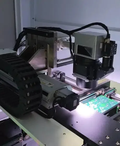
Applications
Electronics & Electrical Laser Marking Applications
Use the product family closest to your part to move from this industry overview into task-specific marking content, geometry and validation requirements.
PCB and PCBA Marking
Data-matrix, batch and logo marks on bare boards and assembled boards, including solder-mask surfaces. See the PCB and PCBA page for the marking content and verification typical of this task.
View PCB markingElectronic Component Marking
Small-character and code marks on ICs, relays, capacitors and other discrete components, where character size, contrast and positional accuracy matter. See the Electronic Component page for detail.
View component markingConnector and Terminal Marking
Housing, terminal and batch traceability marks on connectors and terminals, often with cylindrical or multi-side geometry. See the Connector and Terminal page.
View connector markingMobile Phone Parts Marking
Frames, brackets, housings and internal phone components, frequently anodized aluminum or plastics requiring fine, controlled marks. See the Mobile Phone Parts page.
View phone parts markingCharger and Power Adapter Marking
Housings, ratings and certification information on chargers and adapters, combining plastic and sometimes metal surfaces. See the Charger and Power Adapter page.
View charger markingSwitch and Socket Marking
Panels, icons and plastic contrast marks on switches and sockets, where consistent appearance and legibility across a molded surface are common requirements. See the Switch and Socket page.
View switch markingBattery-cell and module marking for EV and energy-storage applications sits under Energy & Batteries rather than this page because those applications have their own production and safety context.
Result Variables
What Determines Laser Marking Results on Electronic and Electrical Parts?
The product name alone does not determine the result. The same nominal part can behave differently when its substrate, coating, color, geometry, mark size or production requirement changes.
| Variable | Why it matters | What to define |
|---|---|---|
| Material and surface | Absorption and visible surface change depend on the actual substrate, coating, additives, color and finish. | Exact material or known grade, coating, finish, color and supplier variation where relevant |
| Mark content and feature size | Fine text and dense 2D codes require usable edge definition at the required size. | Character height, code size, cell size, line width and marked area |
| Target contrast and surface change | A readable dark or light mark may require a different process window from coating removal or shallow engraving. | Required visual effect and any surface-change limit |
| Geometry and focus condition | Curvature, recesses and height variation can move the surface outside the useful focus range. | Flat, cylindrical, curved, recessed or multi-height features and allowable orientation |
| Positioning tolerance | Small marks can fail even when laser quality is acceptable if the part is not located repeatably. | Datum, fixture tolerance, part variation and whether vision correction is required |
| Production and verification | Cycle time, changing data and code verification can change the complete system even when the optical mark is acceptable. | Parts per hour, loading method, data source, reader or verification requirement |
Material-specific response should still be checked on the actual substrate. Relevant references include electronic substrates, plastics and coated surfaces; these pages support the application decision without replacing the real-part sample test.
Target Result
What Marking Result Should You Target?
Choose the laser after defining what a successful mark must do. In electronics, the target is often a combination of readability, contrast, fine detail, position and acceptable surface impact rather than simply whether the laser can make a visible mark.
| Target result | Typical use | Acceptance focus |
|---|---|---|
| Machine-readable 2D code | PCB, component and product traceability | Reliable reading at the required size with the intended production reader; formal grading only where specified |
| Fine readable text | Part numbers, ratings and small identifiers | Character legibility, edge definition and correct position |
| Consistent visual contrast | Logos, symbols, housings and molded parts | Acceptable light/dark contrast and appearance across representative parts |
| Durable identification where required | Parts exposed to handling or specified environmental conditions | Required durability after the project-specified wear, solvent or exposure test |
| Controlled surface change | Coated, plated, anodized or heat-sensitive surfaces | No unacceptable melting, halo, coating damage, deformation or unintended removal |
| Repeatable mark position | Small parts, fixtures and vision-guided work | Mark stays inside the required location tolerance across repeated loading cycles |
Geometry, Fixturing & Loading
How Do Part Geometry, Fixturing and Loading Affect the Marking Process?
The same mark can require a different machine structure when the part changes from a flat board to a cylindrical connector, loose-position component, tray-loaded batch or in-line production step.
| Part / loading condition | What it changes | Configuration to evaluate |
|---|---|---|
| Flat PCB, panel or housing with repeatable location | Simple focus and datum control | Standard workstation with a suitable fixture may be sufficient |
| Tray, pallet or nest of multiple parts | Repeatable spacing, field coverage and total cycle | Custom fixture, larger usable field or indexed multi-part process |
| Loose-position small parts | Part-to-part XY or angular variation | Vision positioning may reduce manual alignment |
| Cylindrical connector, terminal or tube | Mark surface rotates away from a flat field | Rotary or circumferential setup |
| Curved, recessed or multi-height surface | Focus varies across the marking area | 3D dynamic focus or a controlled reorientation strategy |
| Conveyor or production-line flow | Triggering, handling, data timing and cycle-time balance | Online / flying configuration only when the actual motion and process require it |
Loading method is part of the system decision. Record whether parts arrive individually, in a tray or carrier, on a conveyor, or from another automated station, because fixture design, vision, operator time and verification all contribute to the full production cycle.
Laser Route
Which Laser Type Should You Test First?
No single laser type fits every electronics task. Use the actual surface and target result to choose the first route to test, then confirm the process window on representative parts.
| Laser | Typical reason to test it | What the sample must confirm |
|---|---|---|
| UV (355 nm) | Fine marking on selected plastics, coatings and electronic substrates where thermal impact or small feature size is a concern | Contrast, edge definition, surface condition and repeatability on the exact material |
| Fiber (1064 nm) | Metal housings, plated metal, terminals and selected coated or anodized metal surfaces | Target contrast or surface effect without unacceptable coating or substrate damage |
| MOPA fiber | Applications where wider pulse-width control may help tune contrast or surface response on suitable metal/coated surfaces | Whether the additional pulse control produces a useful, repeatable result on the real part |
| CO₂ | Selected non-metal surfaces where the configured wavelength is appropriate | Material response, edge quality, heat effect and required mark appearance |
Laser type is only the first decision. Field size, lens, spot size, pulse behaviour, fixture, focus control, positioning and extraction can all change the acceptable process window.
For machine families, see UV laser marking machines, fiber laser marking machines and the wider Products section.
Failure Modes
What Are the Common Failure Modes in Electronics Laser Marking?
A visible mark is not automatically a production-ready mark. The failures below are the ones worth looking for during sample testing and pilot production because they usually point back to material response, focus, positioning, settings or system integration.
| Failure mode | What the user sees | What to check first |
|---|---|---|
| Weak or unstable contrast | Mark is difficult to distinguish or changes between parts or batches | Material formulation, coating, color, surface finish and process window |
| Visible heat or surface damage | Melting, halo, discoloration, deformation or excessive layer removal | Laser route, pulse/energy setting, focus and dwell on the actual surface |
| Code looks acceptable but reads unreliably | Production reader intermittently fails even though the code is visible | Cell size, contrast, quiet zone, edge definition, distortion, marking position and reader setup |
| Fine text loses definition | Small characters merge, blur or lose sharp edges | Usable field, focus, spot size, scan settings and height variation |
| Mark position shifts | Content moves outside the drawing or fixture tolerance | Part datum, fixture repeatability, loading variation and vision calibration where used |
| Uneven result across a curved or recessed part | One area is clear while another loses contrast or focus | Surface height, orientation, focus range and need for 3D or reorientation |
| Good sample, poor production consistency | Single test part succeeds but repeated production varies or misses cycle target | Part variation, loading, data handling, verification time, extraction and complete cycle time |
Production Workflow
How Does Laser Marking Fit Into Electronics Production?
Production readiness depends on more than marking time. The complete workflow includes how the part arrives, how the correct data is associated with it, how it is positioned, how the mark is checked and what happens after pass or fail.
| Production step | Decision to define |
|---|---|
| 1. Part loading | Manual single-part loading, tray/pallet, conveyor or upstream automation |
| 2. Part identification and positioning | Fixed fixture, datum confirmation, vision location or rotary orientation |
| 3. Marking data | Fixed content, serial/lot data, code generation and any required production-system input |
| 4. Laser marking | Approved process window for the actual material, mark size and target result |
| 5. Verification | Visual inspection, production-reader check or formal code verification when specified |
| 6. Pass / fail handling | Operator decision, reject path, rework rule or automated signal as required by the line |
| 7. Unloading / next process | Manual removal, carrier transfer or handoff to the next manufacturing operation |
For RFQ or sample-test planning, separate laser marking time from full cycle time. Loading, positioning, data transfer, verification and unloading can become the dominant constraint even when the optical marking step is fast.
Plastic, coated and other process-sensitive materials can generate fumes or debris during marking. Extraction, guarding and complete-system safety requirements should therefore be reviewed as part of the production configuration for the actual material, machine setup and applicable local requirements.
Sample Acceptance
How Should You Accept a Sample Marking Test?
A useful sample test should end with recorded acceptance criteria, not only a visual impression. Test representative real parts and judge the result against the drawing, reader, durability requirement and expected production method.
- Material identity recorded — exact substrate, coating, finish, color and representative batch condition are known
- Mark content is correct — text, serial, code or symbol matches the required artwork or data
- Size and position are acceptable — mark dimensions and location meet the project tolerance
- Contrast and fine detail are acceptable — text and graphics remain legible at the actual required size
- Code reads with the intended reader — and formal grading is performed only when the project specifies a grade and verification method
- No unacceptable surface damage — heat effect, melting, halo, coating removal or deformation stay within the approved limit
- Durability requirement passes — wear, solvent or other exposure is checked when the application actually specifies it
- Repeated samples are consistent — fixture, focus and process settings hold across representative parts rather than one best sample
- Full cycle fits the production target — include loading, marking, verification and unloading instead of quoting scan time alone
Send representative parts together with the marking content, target size, required effect, production rate, loading method, reader or verification requirement, and any automation or data-interface need. Zhuorui Laser can use those inputs to configure and test a marking route before the final machine configuration is fixed.
From Test to Machine
How Do Sample-Test Results Determine the Final Machine Configuration?
The sample test should narrow the configuration. The accepted laser route defines the optical starting point, while geometry, positioning, cycle time, data and verification determine the rest of the system.
| What the test or production review shows | What it changes in the machine configuration |
|---|---|
| The approved result is achieved with UV on the exact plastic, coating or electronic substrate | Use the UV route as the optical basis, then select power, lens/field and machine structure around the accepted process window |
| The approved result is achieved on metal or coated metal with fiber / MOPA fiber | Use the matching fiber route and choose pulse-control capability according to the tested target effect rather than by power alone |
| Small code or fine text only passes in a smaller usable marking field | Lens and field-size selection become part of the final specification |
| Part location varies during loading | Add fixture improvement or evaluate vision positioning instead of relying on manual alignment |
| The mark wraps around a cylindrical part | Add a rotary configuration and validate rotation/indexing repeatability |
| Height variation or curvature causes focus loss | Evaluate 3D dynamic focus, controlled reorientation or a more suitable fixture |
| Manual loading meets the required full cycle | A standard workstation with the validated fixture may be sufficient |
| Manual loading or verification cannot meet throughput | Evaluate multi-part fixtures, conveyor handling, vision, online integration or project-based automation as required |
| Dynamic serials or production data are required | Include software, control and data-interface requirements in the machine review |
| Every code requires post-mark reading | Include reader or vision verification and define pass/fail handling in the system cycle |
| The process creates material-specific fumes or debris | Include appropriate extraction and complete-system safety review in the configuration |
The machine should follow the accepted sample and production conditions. A standard machine is enough when the approved optical result, fixture and manual cycle satisfy the requirement. Vision, rotary, 3D, conveyor or custom automation should be added only when the real part geometry, positioning, data or throughput creates that need.
Next Steps
Turn Your Part Requirements Into a Sample-Test Plan
Start with the real material and surface, required mark content and result, part geometry and loading method, production rate, and how the mark must be verified. Those inputs make the sample test useful for selecting the final machine configuration.
To make a quotation faster, prepare: material and surface · product photos or drawings · marking content and size · target result · part geometry and loading method · production rate · reader / verification requirement · automation or data needs · voltage and destination · sample quantity.