
Industrial Parts Application
Laser Marking for Tools, Hardware & Industrial Parts
Plan permanent identification for tools, fasteners, valves, bearings, nameplates and general machine parts by defining the material and surface, required mark, target result, part geometry, production method and sample-acceptance criteria before the final laser marking system is configured.
Request a QuoteOEM & Custom Inquiry- Permanent part identity
- 2D codes and serial data
- Flat, round and irregular geometry
- Sample-based configuration
Workpiece Scope
Which Industrial Parts and Marking Tasks Are Covered?
Start by identifying the real workpiece family and the permitted mark zone. Material and surface, geometry, handling and production variables are evaluated in the dedicated decision sections below.
Tools
Hand Tools, Power Tools & Cutting Tools
Branding, model data, size, serial numbers, safety symbols and wear-resistant identification on bodies, blades, sockets, bits and accessories.
Explore tool laser markingFasteners
Bolts, Nuts, Screws & Small Hardware
Head marks, grade or size codes, batch identity and compact machine-readable content where limited area and repeatable loading control the process.
Explore fastener laser markingValves & Fittings
Valve Bodies, Fittings & Flow Components
Part numbers, pressure or flow information, directional marks, heat or lot codes and traceability on flat, cylindrical and cast surfaces.
Explore valve and fitting markingBearings
Bearing Rings, Faces & Cylindrical Surfaces
Model, size, batch, origin and traceability content around rings or on narrow faces where focus, positioning and surface integrity need review.
Explore bearing laser markingNameplates
Industrial Nameplates, Rating Plates & Tags
Equipment identity, model and rating data, diagrams, regulatory text and variable serial information on metal or polymer plate formats.
Explore industrial nameplate markingMachine Parts
General Mechanical Parts & Traceability
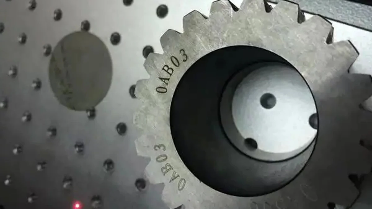
Part numbers, revision, lot, serial and Data Matrix codes on gears, shafts, housings, fixtures and other manufactured components.
Explore machine-part traceabilityWhy Mark
Why Are Industrial Parts Marked?
The marking requirement normally comes from traceability, assembly, service, identification or product-information needs. Define that business and production purpose before comparing laser options.
Part Identification
Keep the part number, model, size, grade, origin or variant directly associated with the physical component throughout production, storage and service.
Traceability
Link a component to a batch, lot, serial number, date code, production record or inspection history when part genealogy is required.
Assembly and Error Prevention
Use orientation marks, flow arrows, torque information, grade marks or machine-readable identity to reduce mix-ups and support correct assembly.
Service and Lifecycle Identification
Preserve information that maintenance, repair and replacement teams may need after the part has left the production line.
Ratings and Technical Information
Keep equipment data, specifications, diagrams, safety information or other required product information readable on plates, tags or the part itself.
Brand and Product Identity
Add logos, manufacturer identity or product-family information where the appearance and durability requirements are compatible with the actual surface.
What Is Marked
What Is Usually Marked on Industrial Parts?
Define the real content, size and mark zone. The smallest character or code feature can affect the optical setup, positioning tolerance and inspection method.
| Marking content | Common part examples | What must be defined |
|---|---|---|
| Brand, logo or origin mark | Tools, fittings, bearing rings, hardware and nameplates | Required appearance, orientation and permitted mark area on the actual finish. |
| Part, model, size or grade | Fasteners, sockets, valves, inserts, cutting tools and replacement parts | Smallest text height, available area and required readability. |
| Serial, lot, batch or date code | Machine parts, calibrated tools, valve bodies and manufactured assemblies | Data source, update frequency, recipe control and part-to-data association. |
| QR or Data Matrix code | Gears, housings, tools, bearing components and traceable hardware | Code size, cell size, reader, lighting and verification method. |
| Directional, torque, flow or assembly mark | Valves, fittings, adjustment parts and installation hardware | Installed orientation, location tolerance and visibility after assembly. |
| Rating plate or specification data | Nameplates, tags, machine labels and equipment plates | Text density, revision control, fixed versus variable information and exposure conditions. |
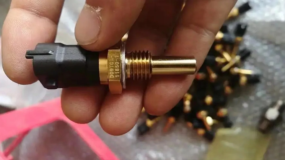
Result Variables
What Determines the Laser Marking Result?
The industry name does not determine the process. The result comes from the interaction between the material and surface, mark definition, geometry, presentation and production requirement.
Material and Surface
Alloy or polymer grade, coating, plating, anodizing, hardness, heat treatment, colour, oxidation and finish can change absorption, contrast, removal behaviour and thermal sensitivity.
Mark Size and Content
Character height, line width, Data Matrix cell size, logo detail, total information density and available mark area determine how much resolution and process time are needed.
Target Effect
High contrast, dark or light colour change, controlled coating removal, shallow engraving or specified depth require different process windows and should not be treated as the same result.
Geometry and Focus
Flatness, curvature, diameter, wrap angle, narrow ring faces and height variation determine whether a fixed focal plane is sufficient or controlled motion is required.
Positioning and Handling
Datum quality, fixture repeatability, rotary runout, part orientation and loading variation determine whether the mark can stay inside its allowed location from part to part.
Takt, Inspection and Data Flow
The real cycle includes loading, locating, marking, verification, reject handling and unloading. Record batch size, target takt, hours per shift, shifts per day and whether operation is sustained or intermittent; variable data, scanner, PLC or MES requirements can add further time and system complexity.
Acceptance Target
What Result Should You Target?
A sample should not be approved because it looks good in one photo. Define the result that must remain acceptable on the real part and under the intended inspection and production conditions.
- ReadabilityText, symbols and logos remain clear at the required size and viewing condition.
- Code verificationQR or Data Matrix codes are tested with the intended reader, lighting and verification method rather than judged visually.
- Contrast, colour or depthThe visible effect or specified depth is defined for the actual alloy, coating and finish.
- DurabilityThe mark remains acceptable after the wear, cleaning or environmental exposure required by the project.
- Part integrityThe process does not create unacceptable change on sealing, bearing, mating, cutting, cosmetic or other protected functional surfaces.
- Position repeatabilityThe mark stays within the permitted location and orientation across repeated loading and part variation.
- Cycle-time resultThe required quality can be repeated within the full production takt, not only during a slow single-part sample.
- Recipe repeatabilityThe approved settings can be identified, controlled and reproduced for the correct part family and surface condition.

Geometry & Handling
How Do Geometry, Positioning and Part Handling Affect the Mark?
Part presentation can change the system architecture as much as the material itself. Define the real loading and datum condition before selecting fixtures, motion or vision.
| Part condition | Examples | Direction to evaluate |
|---|---|---|
| Flat, stationary surface | Nameplates, tool faces, housings, brackets and machined flats | Fixed fixture and standard focal-plane marking after material and target-effect review. |
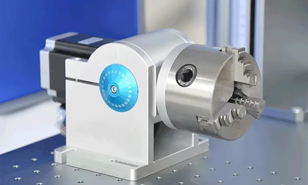
| Cylindrical or circumferential mark | Shafts, sockets, valve stems, fittings and round tool bodies | Rotary cylindrical marking with diameter, wrap angle, chucking and datum control. |
| Ring face or narrow annular area | Bearings, races, collars and washers | Stable nesting, focus tolerance, code size and possible rotary handling. |
| Small part with limited mark area | Fasteners, inserts, bits and compact fittings | Small field, stable nesting, part-present sensing and realistic character or code-size limits. |
| Irregular height or curved surface | Cast valve bodies, formed tools and complex housings | 3D curved-surface evaluation when focus variation across the mark cannot be ignored. |
| Variable placement or mixed orientation | Manual loading, mixed lots and inconsistent fixture position | Vision positioning after the allowable correction range and datum strategy are defined. |
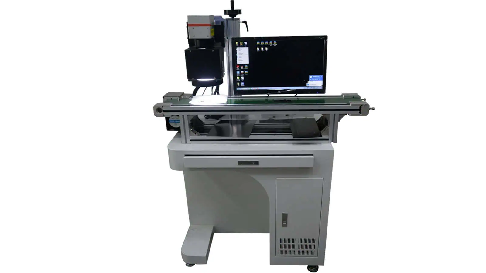
| Conveyor or takt-controlled flow | Hardware lines, parts before assembly and variable serial marking | Flying or online marking with trigger, encoder, spacing and verification review. |
| High-volume loading or multi-station process | Fasteners, bearing rings, tools and repeated machine parts | Automatic marking cell or custom loading concept after full takt analysis. |
First-Test Laser Direction
Which Laser Route Should Be Tested First?
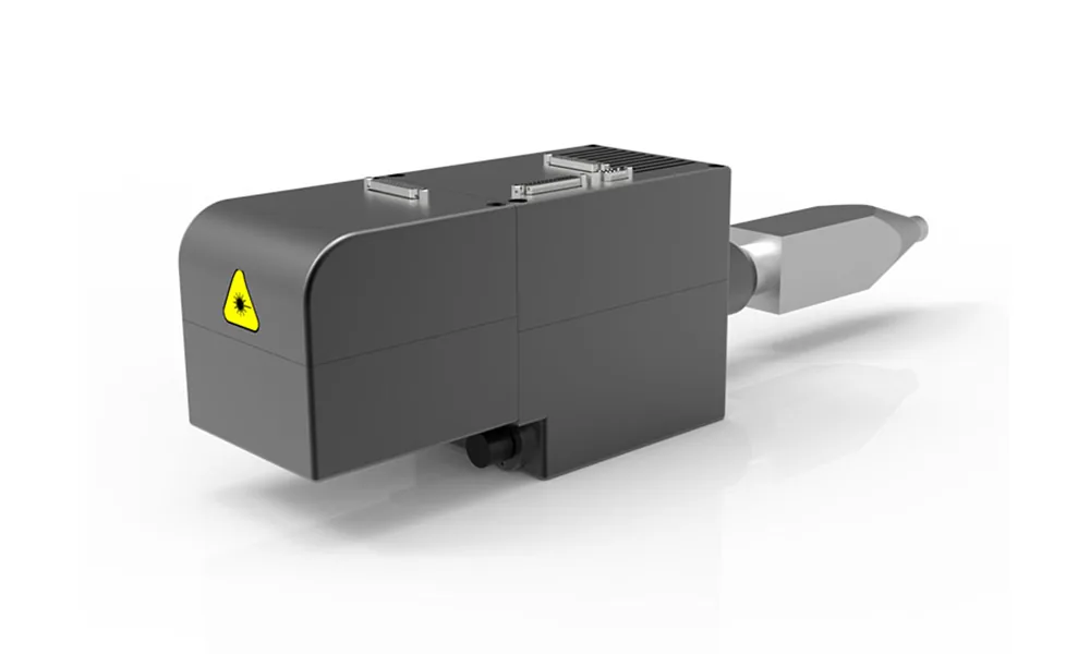
The first test is a starting direction, not a final machine decision. Compare the route that best matches the material and target effect, then use sample results to narrow the process window and system configuration.
| Part condition and target | First route to evaluate | What the sample test must confirm |
|---|---|---|
| Bare steel, stainless steel or tool steel; contrast, identification or engraving | Fiber laser as the baseline; compare MOPA fiber when pulse control may help the target contrast or thermal response. | Contrast or depth, heat effect, surface integrity, smallest feature and cycle time on the real grade and finish. |
| Bare aluminum or anodized aluminum | Fiber or MOPA fiber depending on whether the task is bare-metal marking, anodized-layer contrast or controlled surface change. | Layer response, contrast, edge quality, consistency across finish variation and whether the base material must remain protected. |
| Brass, copper or nickel alloy parts | Fiber-family testing first, with MOPA fiber compared when a broader pulse-control window is useful. | Absorption response, contrast, heat effect, surface finish and the process margin required for repeated production. |
| Engineering plastics with fine detail or heat-sensitive surfaces | UV may be the first comparison when minimizing heat input is important; fiber or MOPA fiber can also be tested where the resin, colour or additives respond appropriately. | Colour change, foaming or surface response, edge quality, distortion, wall integrity and consistency across material batches. |
| Painted, plated or coated metal | Choose the first route from the intended mechanism: mark the top layer, remove it selectively or expose the substrate. Fiber-family and UV tests are common comparison directions. | Whether the correct layer is affected, whether the substrate is protected and whether the transition edge between marked and unmarked areas is stable. |
| Polymer or organic-coated plates and tags | CO₂ may be included in the comparison when the top material absorbs that wavelength effectively; UV or fiber-family testing may still be appropriate for other constructions. | Readability, edge quality, surface damage, residue, contrast and whether the process stays inside the allowed thermal window. |
Failure Diagnosis
Common Failure Modes in Industrial Part Laser Marking
A failed sample should be diagnosed by symptom. Changing laser power alone can hide the real cause when the problem comes from material variation, focus, positioning, code design or production handling.
| Observed failure | Variables to check | First diagnostic action |
|---|---|---|
| Contrast is too low or visually weak | Alloy or polymer grade, coating, finish, focus, pulse conditions, scan strategy | Confirm the real surface and compare controlled parameter changes on the same representative sample. |
| Result varies from part to part | Surface finish, contamination, oxidation, batch variation, focal height, fixture repeatability | Separate material variation from positioning variation before changing the process recipe. |
| Code looks acceptable but does not scan reliably | Cell size, contrast, distortion, quiet area, reader, lighting, mark position | Test with the intended reader and lighting while checking code geometry and placement rather than visual appearance alone. |
| Depth or appearance is uneven across the mark | Curvature, height variation, rotary runout, focus, scan angle | Map the mark zone geometry and confirm whether the full area stays inside the usable focal range. |
| Coating or functional surface is damaged | Wrong marking mechanism, excessive energy, wrong mark zone, insufficient process margin | Reconfirm whether the target is colour change, coating removal or substrate marking, then retest with the protected surface requirement fixed. |
| Mark position shifts between parts | Datum, nest tolerance, orientation, operator loading, vision correction range | Measure fixture and presentation repeatability before assuming the laser field is the source of the error. |
| Circumferential marks do not join or space correctly | Part diameter, chucking, rotary calibration, datum, synchronization | Verify the real diameter and mechanical rotation condition, then check the mark-to-rotation relationship. |
| Sample quality passes but takt is missed | Mark content, scan strategy, loading, locating, verification, reject handling, unloading | Measure the complete cycle and identify the bottleneck instead of comparing laser scan speed alone. |
Production Workflow
How Does Industrial Part Marking Fit into Production?
The production process is more than the laser exposure. Loading, identification, positioning, verification and reject handling all contribute to takt time and final system design.
Load or Present the Part
Manual loading, tray, fixture, conveyor, rotary chuck, robot or other handling presents the workpiece to the marking station.
Confirm Part and Orientation
Part-present sensing, barcode input, recipe selection or visual checks prevent the wrong program from being applied to the wrong workpiece.
Locate the Mark Datum
The fixture, rotary datum or vision system establishes where the mark must sit relative to the real part.
Load Mark Data
Fixed text, serial numbers, database content or PLC/MES data are associated with the correct part and recipe.
Mark the Part
The approved laser and process window create the required contrast, removal or engraving inside the allowed mark zone.
Inspect or Verify
Visual inspection, camera, scanner or verifier checks the acceptance criteria that matter for the actual project.
Pass, Reject or Record
Failed parts are separated when required, while verification results or serial data can be recorded for downstream traceability.
Unload and Repeat
The part exits the station and the next cycle begins. The complete sequence—not laser scan time alone—defines production takt.
Sample Test & Acceptance
How Should Industrial Part Samples Be Tested and Accepted?
Use representative parts and production-like conditions so the sample answers both questions: can the required mark be created, and can it be repeated inside the real production process?
Acceptance Checklist
Test the Real Part, Mark and Production Conditions Together
- Representative part: use the actual material grade, coating, hardness, finish and geometry whenever possible.
- Production content: test the real text, logo, code type, code size and smallest feature instead of an easier demonstration pattern.
- Controlled variables: record the laser route and process settings so the accepted result can be reproduced and compared.
- Mark quality: check readability, contrast or depth, edge quality, position and any protected functional surface.
- Code performance: verify machine-readable marks with the intended reader, lighting and acceptance method.
- Durability: apply the wear, cleaning or environmental checks required by the project rather than assuming permanence from appearance.
- Repeatability: repeat the test across multiple parts or surface conditions that represent the expected production variation.
- Full cycle: include loading, locating, marking, verification, reject handling and unloading when takt matters.
From Test Result to Equipment
How Do Sample-Test Results Determine the Final Machine Configuration?
The final system should be built from the approved sample result plus the real geometry, takt, operating pattern, loading, data and inspection requirements. Laser source and nominal power are only part of that configuration.
| What the test or production review shows | Configuration decision it influences | Why it matters |
|---|---|---|
| Which wavelength and pulse behaviour creates the accepted mark | Laser source family and pulse-control capability | The source must reproduce the required contrast, removal or engraving on the real material and surface. |
| How much process margin is available at the required takt | Power range, pulse/repetition capability and scan strategy | The selected configuration needs enough production margin without using excessive energy as a substitute for process control. |
| Smallest text, Data Matrix cell or logo feature plus total field size | Lens, marking field and optical setup | Field size and feature size must be balanced so the required detail remains readable across the actual mark area. |
| Height variation or curved surface exceeds a fixed focal plane | Focus strategy, Z motion or 3D marking requirement | The mark must stay inside the usable focus range across the real geometry. |
| The mark wraps around a shaft, ring, socket or valve component | Rotary axis, chuck, fixture and datum strategy | Controlled rotation is required when the mark extends beyond the usable tangent area or must maintain circumferential spacing. |
| Part placement varies beyond fixture tolerance | Improved fixture design or vision positioning | The system must correct the real source of positional variation before the mark can repeat reliably. |
| Production volume or takt cannot be met with manual handling | Shuttle table, conveyor, robot, feeder or multi-station automation | Automation is justified by the loading and cycle-time requirement rather than by part type alone. |
| Hours per shift, shifts per day or sustained operation create a higher duty requirement | Duty-cycle margin, workstation design and cooling or thermal-management provision where required by the selected source and system | The configuration must support the planned operating pattern over production time, not only a short sample run. |
| Serial numbers, databases or line controls must change mark content | Software, scanner, PLC, database or MES integration | Data flow has to select and verify the correct content for each part without creating a traceability mismatch. |
| The process requires automatic code or mark verification | Camera, code reader, verifier and reject logic | Inspection hardware and pass/fail handling must match the acceptance method used during validation. |
| Marking produces fumes, coating debris or requires restricted operator access | Extraction, enclosure, interlocks and related safety configuration | Process emissions and operator exposure need to be addressed as part of the final machine and workstation design. |
FAQ
Additional Industrial Part Laser Marking Questions
Can laser marking replace labels or ink on industrial parts?
It can provide direct identification for many applications, but the decision depends on required contrast, durability, surface condition, mark content and whether the part permits the intended laser effect. A representative sample should be tested before changing the production method.
Is deeper marking always better on metal parts?
No. Depth is only useful when the application requires it. Excessive removal can increase cycle time or affect a protected functional surface, so depth should be specified as an acceptance requirement rather than treated as a general quality target.
Can one laser setup cover several different industrial parts?
Sometimes, when the materials, mark effects, field size and handling requirements stay inside a shared process window. Mixed alloys, coatings, geometries or inspection requirements may need different recipes, optics, fixtures or even a different laser route.
Next Steps
Start an Industrial Part Marking Review
Share the workpiece, material and surface, required mark, target result, part geometry, quantity, takt and operating pattern. A representative sample test can then be used to narrow the laser route and define the required optics, fixture, motion, automation, inspection and data configuration.
Prepare: part type · material and finish · photos or drawings · marking content and size · mark zone · target result · inspection method · quantity and takt · hours/shift and shifts/day · loading or fixture method · automation/data needs · representative samples.