
Mechanical Parts · QR & Data Matrix · Serial Numbers · Batch Identification
Laser Marking for Machine Part Traceability
Plan permanent identification for gears, shafts, housings, fixtures, tooling and other manufactured parts by defining the real workpiece, mark content, target result, positioning method, production volume and sample acceptance criteria before choosing the final laser system.
Start with the workpiece
Is this the right laser marking application for your machine part?
Machine-part traceability covers permanent identification placed on manufactured components so the part can be identified, scanned, linked to production information or checked later in its life. The starting point is not the laser model. It is the real part, its surface, the mark that must be created and the way the part will be presented in production.
Before sample testing, define six inputs
- Part type and material or coating.
- Exact marking zone and available area.
- Text, serial, batch or 2D-code content.
- Required visual and machine-readable result.
- Part orientation, fixture and loading method.
- Production volume, cycle target and verification method.
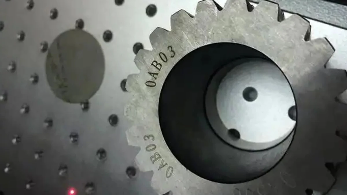
Purpose before process
Why are machine parts marked?
A permanent mark is useful when the identity on the physical part must stay connected to a drawing, production event, inspection record, assembly, service history or downstream traceability process. The purpose determines what data should be marked and how strict the acceptance test needs to be.
Keep similar parts distinguishable
Part numbers, revisions and model identifiers help separate components that may look similar but belong to different drawings, assemblies or production states.
Connect one physical part to a record
A unique serial number or 2D code can provide the key used to associate the marked part with work-order, process, inspection or service data.
Link groups of parts to a production event
Lot and batch codes support grouping by production run, material lot, process stage or other buyer-defined record structure.
Preserve identification after production
Where required, the mark can support assembly, maintenance, replacement, return analysis or other later-stage identification after labels or packaging are gone.
What is marked?
What Is Marked on Machine Parts?
Separate fixed part identity from unique serial data and production-batch information. The marking file should then distinguish what stays constant from what changes for every part or production lot, because that distinction affects data generation, duplicate control, verification and rework handling.
| Mark content | Typical role | Input required | Acceptance check |
|---|---|---|---|
| Part number and revision | Identifies the component design or drawing state. | Approved text format, revision rule, character size and marking zone. | Correct content, orientation and legibility. |
| Unique serial number | Identifies one physical part. | Serial source, sequence rule, duplicate prevention and rework handling. | Correct serial and correct record association. |
| Lot or batch code | Links a group of parts to a production event. | Batch format, update timing, operator permissions and changeover rule. | Correct batch at the correct production stage. |
| QR or Data Matrix code | Encodes an identifier, URL or traceability payload. | Payload, overall code size, module or cell size, scanner, lighting and verification target. | Readability on the actual part under the agreed scanning conditions. |
| Logo or required text | Adds brand, model or other human-readable information. | Artwork, minimum feature size, visual priority and protected areas. | Readable appearance without unacceptable effect on the part. |
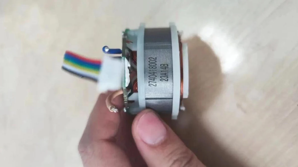
Result variables
What determines the laser marking result?
The same QR code or serial number can behave very differently on two parts that share the same nominal material. Surface condition, feature size, geometry, positioning and production requirements all change the usable process window.
| Variable | What to define | Why it changes the result |
|---|---|---|
| Material and surface | Alloy or polymer where known, coating, anodizing, plating, oxide, oil, scale, roughness and normal lot-to-lot variation. | Laser absorption and the desired surface reaction depend on the real production surface, not only the material family name. See the relevant steel, stainless steel, aluminum or material guidance when the substrate needs separate evaluation. |
| Target mark effect | Visible contrast, shallow engraving, deeper identification, coating removal or another approved surface change. | Different mark mechanisms require different process windows; a setting that gives strong contrast is not automatically the right setting for depth, surface preservation or speed. |
| Code and feature size | Character height, line width, 2D-code size, module or cell size, payload and quiet area where applicable. | Smaller features reduce tolerance for focus error, distortion, low contrast and rough surfaces. |
| Geometry and marking zone | Flat, cylindrical, recessed, curved or height-varying area; available field size and nearby walls or shoulders. | Geometry affects focus, optical access, distortion and whether one static marking field can cover the required area. |
| Positioning and part variation | Datum, fixture repeatability, orientation tolerance, runout, part-to-part position variation and changeover method. | A stable laser process can still fail if the mark lands in the wrong place or the surface height changes outside the validated focus range. |
| Production requirement | Batch size, parts per shift, required cycle time, duty cycle, manual or automatic loading, changeover frequency and inspection time. | Process time is only one part of throughput. Loading, positioning, data handling and verification can become the real cycle constraint. |
Acceptance target
What should an acceptable machine-part mark achieve?
Define the pass condition before tuning parameters. A mark is only successful when it meets the buyer’s actual identification and production requirements, not merely when it looks dark or visible in a photograph.
Geometry, positioning and handling
How do shape, positioning and loading affect the marking setup?
Geometry determines whether the target area stays within the usable focus range. Positioning determines whether the mark lands in the same place every cycle. Part handling determines how repeatably the workpiece can be presented and how much of the total cycle is spent outside the laser process itself.
When geometry creates the requirement, review rotary marking for cylindrical coverage, vision positioning for variable part location, or 3D curved-surface marking for meaningful height or surface-form variation.
First-test direction
Which laser route should be tested first?
The first test should follow the real surface and target effect. It should not be chosen only from the part name or by assuming that higher laser power automatically produces a better mark.
| Workpiece condition | First route to evaluate | What the sample test must prove |
|---|---|---|
| Bare steel, stainless steel, aluminum or many other metal parts | Start with a fiber-laser process evaluation when the target is compatible with metal marking. | Confirm the required contrast or engraving effect, acceptable heat input, feature quality and cycle time on the real finish. |
| Metal parts needing tighter pulse control, fine surface control or a specific appearance | Evaluate a MOPA fiber source when adjustable pulse characteristics could widen the process window. MOPA is a fiber-laser source type, not a separate wavelength family. | Compare process stability, surface effect, edge quality and speed against the acceptance target rather than selecting MOPA by name alone. |
| Anodized, painted, plated or otherwise coated metal | First define whether the mark should remove the top layer, modify it, or preserve it while changing the visible result; then test a route that matches that mechanism. | Verify contrast and readability without unacceptable penetration, substrate exposure, coating damage or edge burning. |
| Plastic insert, polymer machine part or mixed-material assembly | Do not default to the metal route. Test the actual polymer, additives, color and adjacent materials; UV, green or fiber routes may be candidates depending on the construction and target effect. | Check contrast, thermal effect, feature definition and whether neighboring materials or assembled components are affected. |
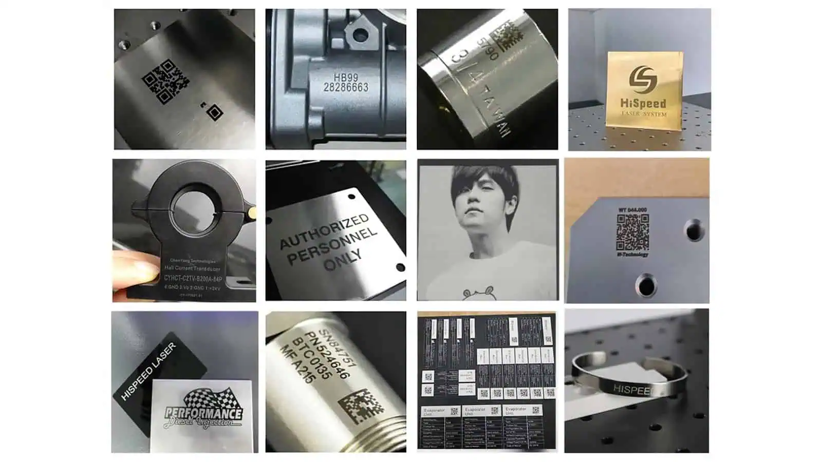
The sample test should compare only routes that fit the material and target result. Final source capability, pulse range, lens, field size and power level should be selected from the validated process window rather than from a generic machine-parts rule.
Failure diagnosis
Where do machine-part marking projects commonly fail?
A failed mark does not always mean the laser source is wrong. Code design, focus, surface variation, part positioning, data logic and handling can produce similar symptoms, so the first check should follow the observed failure.
| Observed problem | Check first | How to confirm the cause |
|---|---|---|
| QR or Data Matrix code looks visible but does not scan reliably | Code size and module size, contrast, surface texture, curvature, focus, distortion, scanner and lighting. | Scan the same sample with the intended reading setup, then change one variable at a time instead of increasing power blindly. |
| Contrast varies between nominally identical parts | Oil, scale, oxide, coating thickness, roughness, alloy or lot variation, focus height and cleaning state. | Compare parts with documented surface condition and fixed laser parameters to separate material/surface variation from parameter drift. |
| Mark position shifts from part to part | Fixture datum, orientation, runout, manual loading variation, part tolerance and vision reference. | Measure the part position before changing laser parameters; repeat the test with a controlled fixture or reference method. |
| Surface is burned, melted, burred or a coating is penetrated too far | Energy density, pulse behavior, overlap, focus and the actual layer structure. | Reduce the test to a controlled parameter matrix and inspect whether the target effect can be reached before unacceptable surface damage begins. |
| Serial numbers repeat or the wrong data is marked | Data source, sequence state, work-order logic, restart behavior, rework permissions and duplicate prevention. | Run controlled normal, restart and rework scenarios and confirm that the physical mark matches the intended record each time. |
| Mark quality passes but the production cycle is too slow | Mark content density, mark size, laser process time, loading, fixture changeover, scanning and verification time. | Time each step separately. Optimize the actual bottleneck instead of assuming the laser source alone limits throughput. |
Production workflow
How does machine-part marking move from data to a released part?
A production traceability workflow should control both the physical part and the data associated with it. The exact automation level can range from a manual station to a connected cell, but the sequence should remain understandable and testable.
When the requirement includes work-order transfer, serial control, PLC/MES/ERP interfaces, verification feedback or duplicate prevention, review the traceability and data-integration options in addition to the laser process itself.
Sample acceptance
How should a machine-part sample be tested and accepted?
A useful sample test uses real production parts, including normal surface and dimensional variation. It should reproduce the intended marking position, data format, loading method and inspection conditions closely enough that the result can guide the machine configuration.
- Provide representative parts, drawings or clear photos of the actual marking area.
- Record material, finish, coating, oil, scale or other surface conditions that may vary in production.
- Provide the exact text, serial rule, batch format and QR or Data Matrix payload.
- Define minimum character or code size, scanner or verification method, lighting and viewing conditions.
- Reproduce the intended datum, fixture, orientation tolerance and part-height range.
- Measure mark time together with loading, positioning and verification time when cycle is part of acceptance.
- Include any required cleaning, abrasion, oil exposure, assembly or other downstream handling check.
Pass only against agreed criteria. A representative sample should be judged for correct content, readable result, position repeatability, acceptable surface effect, required durability and production cycle. A visually attractive photograph alone is not enough for a 2D-code or traceability application.
What should the sample-test record contain?
A sample-test record should preserve enough information to connect the physical part, test conditions, inspection method and resulting engineering decision. That makes the result reviewable and helps prevent it from being applied to a different part or surface without evidence.
| Record field | What to capture | Why it matters |
|---|---|---|
| Part and sample identity | Part number or sample ID, material, coating or finish, drawing/revision where relevant. | Prevents a result from being reused on a different construction without evidence. |
| Marking requirement | Marking zone, text/serial/batch rule, code payload, code size and target appearance or depth. | Defines exactly what the sample was intended to achieve. |
| Test setup | Laser route, relevant process settings, field/lens condition, focus method, fixture or rotary/vision method if used. | Connects the observed result to the configuration that produced it. |
| Inspection method | Scanner or verifier, lighting, visual criteria, position check, durability or downstream test where required. | Makes the acceptance result reproducible instead of subjective. |
| Cycle and handling | Mark time, loading/positioning method, verification time, changeover condition and production target. | Shows whether the process can meet the real production requirement. |
| Observed result and decision | Pass/fail items, photos or measurement records, remaining limitations and the configuration changes required next. | Creates the link from sample evidence to final machine selection. |
From test result to equipment
How do sample-test results determine the final machine configuration?
The final system should be a response to what the sample test proves. Material response selects the usable process window; geometry selects how the part is presented; code and data requirements select the verification and software path; production volume determines how much handling and automation are justified.
| What the test or production study shows | Configuration implication | Decision logic |
|---|---|---|
| A stable marking window is confirmed on the real material and surface. | Laser source family, pulse capability and practical process margin can be specified. | Select the source from the validated effect and cycle requirement rather than from material name alone. |
| The required mark area or code size approaches the usable field limit. | Field size, lens and working distance need to be selected together. | Larger fields change spot size and process conditions, so field choice should be validated with the actual feature requirement. |
| The part is cylindrical or the mark must cover more than one angular position. | Rotary axis, chuck/fixture design or another controlled motion method may be required. | The machine needs motion only when the static field cannot present the required surface correctly. |
| Part height or surface form varies beyond the static focus tolerance. | Z adjustment, height sensing or a suitable 3D/dynamic-focus approach may need evaluation. | The focus strategy follows the measured height variation and required mark area. |
| Part location or orientation varies too much for a simple fixed fixture. | Vision positioning or a better mechanical datum may be justified. | Use the simplest method that repeatedly places the mark inside the approved zone. |
| Serials or 2D codes must come from work orders and verification must return a result. | Scanner/vision, software, database or PLC/MES interface requirements become part of the system definition. | The data architecture is driven by how the physical mark must be associated with production records. |
| Mark quality passes but throughput fails because handling dominates the cycle. | Fixture optimization, dual-station handling, automatic loading or a different cell layout may be more important than changing laser power. | Improve the measured bottleneck rather than assuming source power is the only route to higher output. |
| Production includes frequent part changes or multiple variants. | Fixture changeover, recipe control, adjustment range and operator-proofing should be included in the machine design. | A process that works on one sample still needs repeatable setup across the real product mix. |
| High daily volume or long duty periods are required. | Station layout, component duty capability, guarding, extraction, handling and maintenance access need to match the real operating pattern. | Production volume affects the complete workstation, not only the nominal laser source rating. |
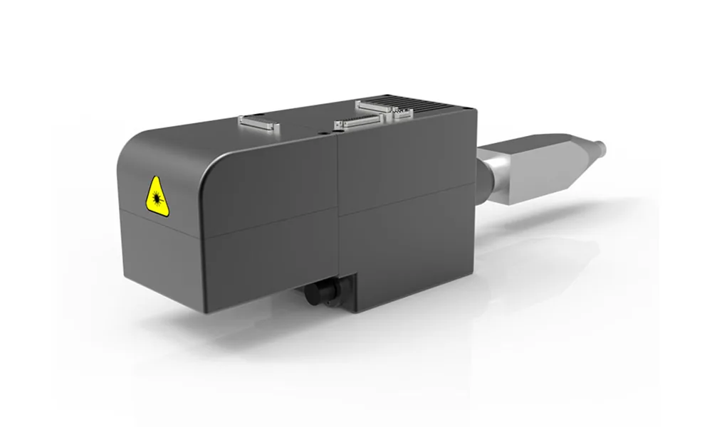
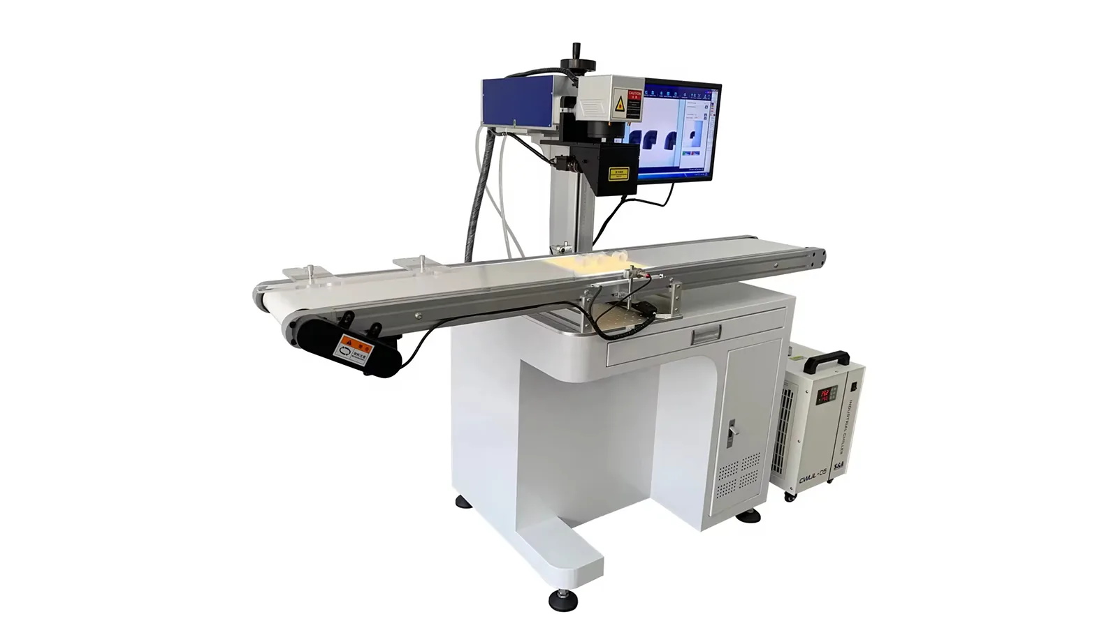
For many metal machine parts, a fiber laser marking machine is a logical category to evaluate after the process window is known. Use OEM & Custom Inquiry when the validated requirement includes non-standard fixtures, rotary or multi-axis motion, vision, automatic loading, traceability integration or another project-specific system requirement.
Start with the real workpiece
Turn the machine-part requirement into a testable specification
Share the part material and surface, marking zone, text or 2D-code requirement, target result, positioning method, production volume, cycle target and acceptance method. Those inputs can be used to plan a sample test and determine which laser, lens, fixture, motion, verification and integration functions are actually needed.