
Laser Marking for Glass, Crystal and Ceramics
Separate glass type, residual stress, coating, glaze, ceramic composition and focus position before selecting a UV, green, CO2 or confirmed internal/subsurface route. Brittle materials need crack control, surface inspection and sample validation before a laser marking machine is recommended.
Request a Quote OEM & Custom InquiryBrittle Materials Need Thermal, Stress and Focus Control
Glass, crystal and ceramics can be laser marked, but they cannot be selected by appearance alone. Soda-lime glass, tempered glass, borosilicate glass, coated glass, crystal, glazed ceramic, alumina and zirconia each have different absorption, residual stress, surface behavior and crack risk.
The production test should use the final part condition. Marking a clean flat coupon before tempering, polishing, glazing, coating or assembly may not predict the delivered component.
Return to all laser marking materials.
Which Brittle Material Are You Actually Marking?
The same artwork can produce different results when the material, surface treatment or stress state changes. Treat each glass, crystal and ceramic condition as its own qualification case.
Glass type and stress state
Soda-lime, borosilicate, tempered, laminated and coated glass can react differently. Tempered or stressed glass needs crack and strength criteria in the final condition.
Crystal and transparency
Transparent blocks and crystal items require optical clarity, focus depth, viewing angle and internal-scatter review when the target is not only surface marking.
Ceramic body and glaze
Glazed ceramic, unglazed ceramic, alumina and zirconia may mark through glaze change, pigment response, ablation or body interaction. Do not transfer one ceramic approval to another grade.
Surface stack
Paint, film, functional coating, polish, glaze and contamination may be the real marking target. Test the complete stack, not only the base material name.
Choose the Exact Glass, Crystal or Ceramic Route
Use the route that matches the actual substrate or surface system. Each destination owns more specific material behavior, risks and sample-test requirements.
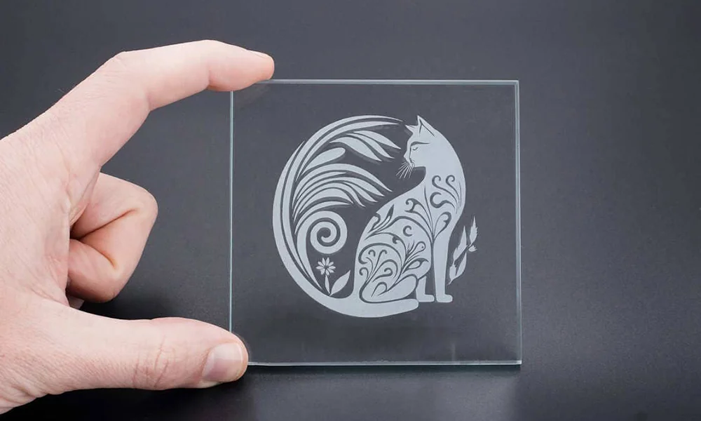
Glass Surface Laser Marking
Choose between frosting, micro-ablation, coating removal and fine coding based on glass type, thickness and stress state.
Explore this route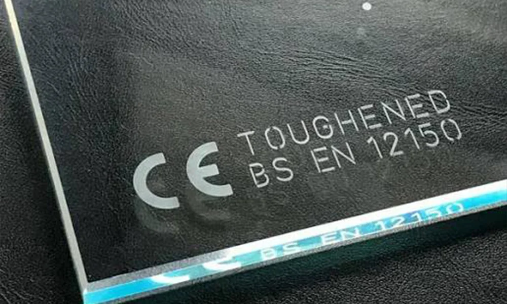
Tempered Glass Laser Marking
Treat residual stress and crack risk as release criteria. Test the final tempered condition, not untreated glass.
Explore this route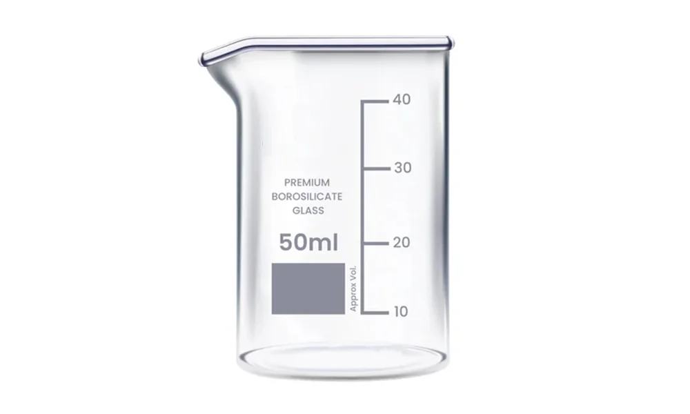
Borosilicate Glass Marking
Control focus, pulse energy and thermal load to limit chipping and microcracks on laboratory or technical glass.
Explore this route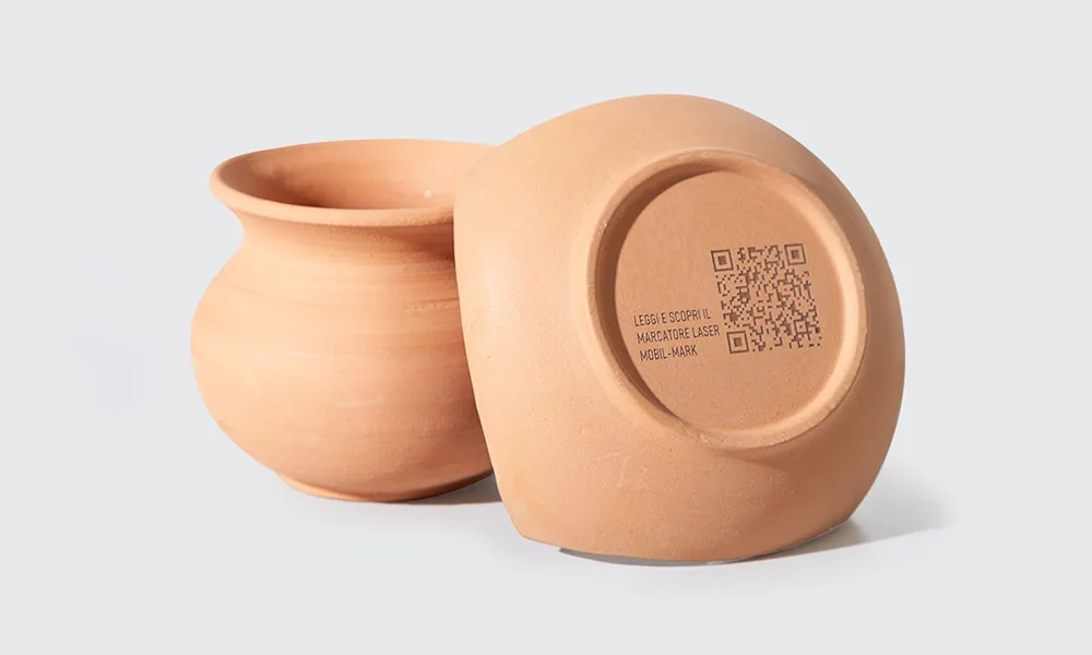
Ceramic Laser Marking
Separate glazed, unglazed and technical ceramics because the mark may alter glaze, pigment or the ceramic body.
Explore this route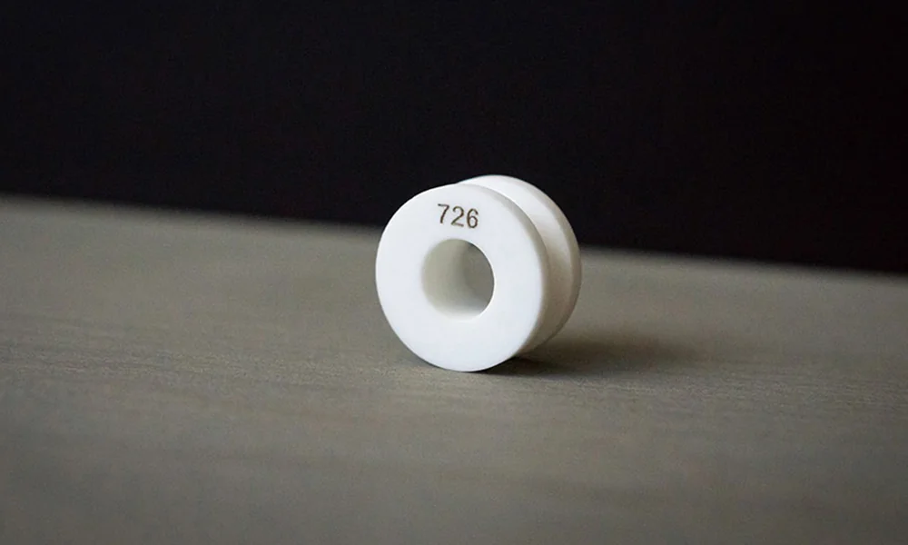
Alumina Ceramic Marking
Validate fine-code contrast, ablation depth and edge quality on the actual alumina grade and surface finish.
Explore this route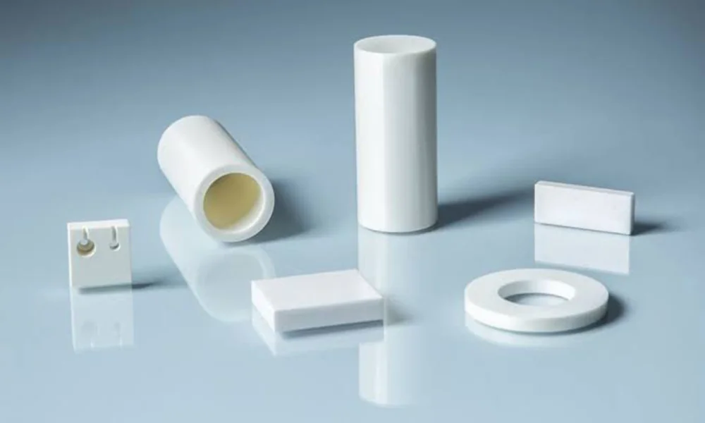
Zirconia Ceramic Marking
Evaluate surface color, polish, heat response and cosmetic acceptance before releasing production parameters.
Explore this routeWhere Glass, Crystal and Ceramics Are Used — and Why They Are Marked
The marking requirement usually starts with the product task: permanent identification, traceability, coding, branding, personalization or functional reference marks. The substrate then determines how safely and consistently that result can be created.
Glass bottles, jars and packaging
Date codes, batch or lot identification, logos and permanent product coding are common. Production speed, curved surfaces, coating condition and crack risk all affect the process choice.
Display, appliance and electronics glass
Small identification marks, serial numbers, reference marks and machine-readable codes may be needed on cover glass, panels or technical windows. Fine features and cosmetic acceptance usually matter more than mark size alone.
Laboratory and technical glassware
Part identification, graduations, calibration references, serial numbers and durable traceability may be required. Glass type, wall thickness and local stress are important before releasing a process.
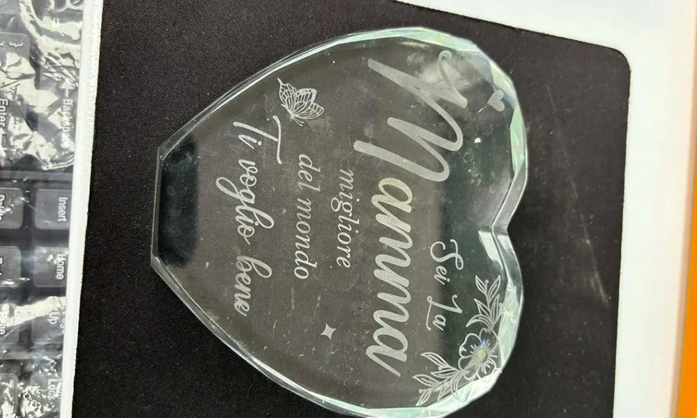
Crystal gifts and personalized products
Names, dates, logos, decorative graphics and internal effects are common. Cosmetic quality, viewing angle and focal depth are more important than high throughput in many of these applications.
Electronic and technical ceramic parts
Serial numbers, lot codes, Data Matrix codes and part IDs support traceability through assembly, testing and service. The ceramic grade, glaze and surface finish can change contrast and edge quality.
Consumer and industrial ceramic products
Logos, product identifiers, decorative marks and permanent codes may be required on glazed or unglazed surfaces. The desired appearance must be checked against glaze damage, ablation depth and batch consistency.
What Is Usually Marked on Glass, Crystal and Ceramics?
The content being marked changes the process requirement. A large decorative logo, a fine serial number and a machine-readable Data Matrix code do not have the same tolerance for contrast, edge definition or positioning error.
Traceability and production codes
Serial numbers, batch or lot codes, date codes, QR codes, Data Matrix codes and barcodes are common where parts must be identified through manufacturing, inspection or service.
Branding and product information
Logos, model information, names, dates, warning text and permanent product labels may be marked when ink, stickers or transferred labels are undesirable.
Functional and decorative marks
Graduations, scales, alignment references, decorative graphics, personalization and suitable internal crystal graphics can require different optical and quality criteria from ordinary text marking.
Machine-readable codes need their own acceptance criteria
Define code size, quiet zone, contrast, edge quality, lighting and reader verification before finalizing the process. A code that looks visible to the eye is not automatically reliable for production scanning.
What Marking Result Do You Need?
Start with the result the user or production line must accept, then choose the laser route and inspection method. “A visible mark” is not a complete requirement for brittle materials.
| Desired result | Typical use | What can go wrong | What to approve |
|---|---|---|---|
| Frosted or matte surface mark | Glass logos, text, decorative marks and larger visible identifiers | Chipping, haze outside the mark, rough edges, microcracks or inconsistent frosting | Appearance, edge quality, crack condition, cleaning result and repeatability |
| Fine text or machine-readable code | Serial numbers, Data Matrix, QR and small traceability marks | Weak contrast, broken modules, blurred edges, focus variation or reader failure | Character definition, code readability, lighting condition, placement and cycle stability |
| Selective coating removal | Painted, coated, mirrored or functional glass / ceramic layers | Over-removal, substrate damage, residue, uneven exposure or delamination | Layer selectivity, exposed appearance, residue, substrate protection and edge definition |
| Color, pigment or glaze change | Glazed ceramics and selected technical ceramic surfaces | Uneven color, glaze damage, excessive ablation, gloss change or batch variation | Contrast, cosmetic acceptance, glaze integrity, readability and post-cleaning condition |
| Internal or subsurface effect | Transparent crystal, glass blocks and selected clear components | Focus sensitivity, internal cracks, scatter, bubbles or low visibility | Focal depth, optical clarity, viewing angle, dot quality and part stress condition |
How Do Shape, Thickness and Part Size Affect Laser Marking?
A process that works on a flat coupon can change when the real part is curved, thin, thick, close to an edge or larger than the marking field. Geometry affects focus, local stress, fixture design and machine configuration.
Flat vs. curved surfaces
Bottles, tubes and curved ceramic parts change working distance across the mark. Uneven focus can change line width, contrast and energy density, so rotary fixtures, controlled orientation or 3D focus may need to be evaluated.
Thin walls and thin glass
Lower mass and local stress can make heat accumulation, cracking or chipping more sensitive. The final wall thickness should be included in sample testing.
Thick transparent parts
For internal marking, focal depth, refraction, optical path and internal stress become more important as the beam is focused inside the material rather than on the surface.
Edges, holes and corners
Marks near an edge, hole, notch or corner can be more sensitive to stress concentration. Placement should be tested on the real geometry rather than assumed from a center-of-panel coupon.
Large parts and large mark areas
If the part or artwork exceeds a practical single field, the system may need a larger field, XY motion, indexing or controlled repositioning. Field size should not be increased without checking spot size and quality requirements.
Height variation and fixture repeatability
Stepped, warped or inconsistent parts can move the surface out of focus. Fixture consistency, autofocus, height compensation or 3D focus may be required when the height variation is larger than the stable process window.
Which Laser Route Should You Test First?
Do not select a laser marking machine for glass or ceramic by wattage alone. The useful route follows material absorption, stress state, target effect, mark location, feature size, surface layer and whether the process is on the front surface, back surface, coating interface or inside transparent material.
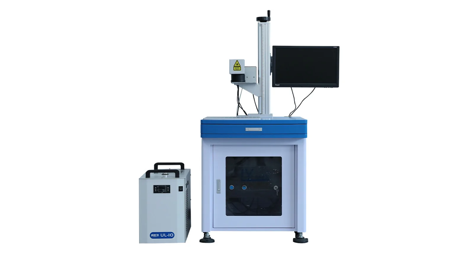
Compare product category routes through UV laser marking machines, green laser marking machines, CO2 laser marking machines and broader laser marking machines after sample response is known.
| Laser route | Where it may be evaluated | Boundary to keep |
|---|---|---|
| UV laser | Fine surface marks, selected coated glass, ceramics, small codes and lower visible heat input requirements | Contrast, cycle time and crack risk still depend on the actual material, coating and focus. |
| Green laser | Selected transparent, reflective or brittle-material trials where sample response supports the route | Use as a confirmed test route only; do not present it as a universal glass or ceramic solution. |
| CO2 laser | Glass surface frosting, larger marks, coating removal and selected ceramic surface work | Heat stress, edge quality, fine-code readability, smoke and coating debris must be controlled. |
| Internal / subsurface system | Transparent crystal, glass or clear blocks where the mark must be inside the material | Requires dedicated optics, controlled focal depth and confirmed equipment scope. It is not automatically available from normal surface marking equipment. |
Practical first-test direction
| Typical task | First route worth evaluating | What must still be confirmed |
|---|---|---|
| General glass surface frosting or larger visible marks | CO2 | Crack risk, edge quality, haze, heat load and cycle time on the final glass condition. |
| Fine marks, small codes or selected coated glass | UV | Contrast, coating selectivity, code readability and surface damage. |
| Selected transparent or brittle-material response where absorption is favorable | Green | Real sample response, optical path, thermal effect and production stability. |
| Fine ceramic marking | UV or another sample-proven route | Ceramic grade, glaze, pigment response, contrast and surface integrity. |
| Marking inside transparent crystal or glass | Dedicated internal / subsurface system | Focal depth, internal crack risk, optical clarity and confirmed equipment scope. |
Do not lock the machine configuration before the sample route is proven
Laser source, field size, focus method, fixture, vision, 3D focus, extraction and motion configuration should be selected after the required mark effect is stable on the actual substrate. Wattage alone is not a reliable selection rule for glass, crystal or ceramics.
Include Crack, Chip, Haze and Strength Criteria in Release Checks
Brittle-material failures may not be obvious in a quick photo. Microcracks, chipping, glaze damage or strength reduction can appear after cleaning, thermal cycling, assembly pressure or normal handling.
- Inspect for microcracks, chips, haze, scattered dots, edge roughness and glass flakes.
- Compare untreated, tempered, polished, coated and assembled states as separate samples.
- Check front-side, back-side and internal focus positions independently.
- Review fixture pressure, contact points and part support to avoid stress concentration.
- Define whether normal visual inspection is enough or whether magnification or strength testing is required.
- Check for weak or inconsistent contrast, especially when surface finish, coating or ceramic pigment changes between batches.
- For QR or Data Matrix codes, verify readability with the intended reader and lighting instead of approving by eye alone.
- Watch for excessive ablation, uneven coating removal, coating delamination or gloss change that may be unacceptable even when the mark is visible.
- Re-test when focus height, fixture support, temper, coating, glaze, supplier grade or final assembly condition changes.
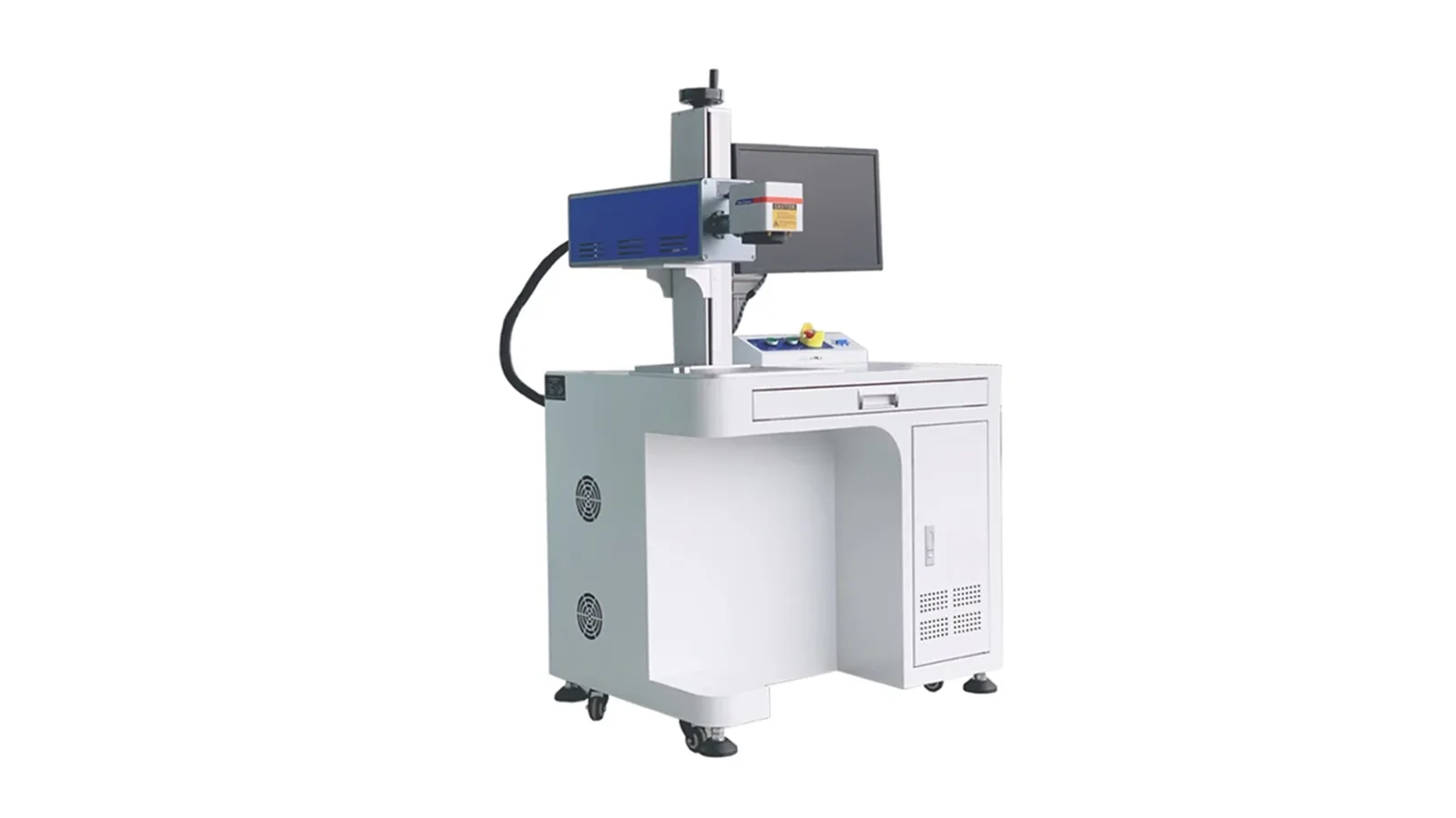
Review Radiation, Reflection, Enclosure and Fume Controls Before Testing
Glass, crystal and ceramic marking can involve UV, visible green, infrared CO2 or other laser routes. The safe machine form depends on the complete system configuration, not only the laser source or the fact that a cabinet is present.
Beam and reflection control
Transparent, glossy, curved or glazed surfaces can change beam paths and reflection behavior. Review direct and reflected beam risks, beam stops, controlled access and whether the work area should be enclosed for the selected source.
Enclosure and operator protection
Laser class is a system-level result. Confirm enclosure design, door interlocks, emergency stop, viewing window filtering and wavelength-appropriate eyewear for the actual UV, green, CO2 or internal marking setup.
Fume, dust and coating residue
Coatings, glaze, paint, films and ablated ceramic or glass residue may require local extraction and suitable filtration. Review SDS or coating information before repeated testing or production release.
Safety information is configuration dependent
This page gives material-selection guidance only. Final safety controls should be confirmed for the actual machine layout, laser source, enclosure, optics, fixture, material stack and local workplace requirements.
Brittle-Material Sample-Test Matrix
Final approval should be based on production-grade samples and defined inspection criteria, not on material name or a representative test coupon alone.
| Input | What to define | Why it matters |
|---|---|---|
| Material state | Glass type, crystal type, ceramic body, temper, glaze, coating, polish and final assembly state | Represents the real stress, absorption and surface condition. |
| Focus location | Front surface, back surface, coating interface, glaze layer or internal focal position | Controls mark location, energy density and optical path. |
| Target result | Frosted mark, micro-ablation, coating removal, color/glaze change, readable code or internal effect | Each effect has different source, parameter and inspection requirements. |
| Quality limits | Chipping, cracks, haze, debris, edge definition, glaze damage and cosmetic acceptance | Defines what a production-approved mark means. |
| Readability | Character size, Data Matrix or QR code size, lighting, contrast and reader settings | Verifies the actual identification task, not just a visible mark. |
| Handling and durability | Fixture pressure, cleaning, abrasion, heat cycling, chemical exposure or strength checks | Prevents release based on a fragile or non-durable one-off sample. |
Do not use substitute samples for final approval
If the production part is tempered, coated, glazed, polished, laminated, bonded or assembled, the submitted sample should match that condition. A flat untreated coupon can lead to the wrong machine or parameter recommendation.
From sample test to production approval
Actual production sample → small parameter matrix → visual or magnified inspection → code readability check when applicable → cleaning / abrasion / heat / strength checks when required → final assembled-condition confirmation → freeze the approved process window and machine configuration.
If the material grade, supplier, temper, coating, glaze, thickness, fixture support or mark location changes after approval, treat that change as a reason to re-test rather than assuming the original result transfers automatically.
From Sample Result to Final Machine Configuration
The final machine should be configured from the proven sample process and the real production conditions. The same mark can require a different system when part geometry, positioning tolerance, target throughput or inspection method changes.
| Production input | Configuration it helps determine | Why it matters |
|---|---|---|
| Material and sample response | Laser source / wavelength and usable process window | The route must first create the required mark without unacceptable cracking, chipping, glaze damage or coating failure. |
| Mark size and feature size | Lens, marking field and optical setup | A larger field is not automatically better if it reduces the spot or feature quality needed for fine codes. |
| Fine code or positioning requirement | Fixture, vision, reader verification and control workflow | Readable codes need stable placement, focus and verification, not only visible contrast. |
| Curved or variable-height part | Rotary fixture, custom nest, autofocus or 3D focus | Focus variation can change contrast, line width and process stability across the part. |
| Large part or large mark area | Larger field, XY motion, indexing or controlled repositioning | The system must cover the required area without losing the needed mark quality. |
| Target cycle time / parts per hour | Manual, semi-automatic, multi-station or inline architecture | Scan speed alone does not define full production cycle time; loading, positioning, focusing, marking and verification all contribute. |
| Dust, coating residue or debris | Extraction and filtration | Repeated production may need local extraction appropriate to the actual coating, glaze or ablated material. |
| Operator and system safety requirement | Enclosure, interlocks, viewing protection and controlled access | The final safety level belongs to the complete machine configuration, not the laser source alone. |
What to send for a useful recommendation and quotation
- Material type, grade when known, temper, coating or glaze, thickness and surface finish.
- Actual part dimensions, geometry, mark location and whether the target is front surface, back surface, coating interface or internal.
- Artwork or code file, smallest feature, target contrast / texture and any readability requirement.
- Quality limits for cracks, chipping, haze, debris, glaze damage, cosmetic appearance and durability.
- Target cycle time or parts per hour, loading method, fixture constraints and operator workflow.
- Positioning / vision needs, inspection method, extraction constraints and enclosure / safety requirements.
- Production-grade samples whenever possible so the route and machine configuration can be based on the real part rather than a substitute coupon.
Glass, Crystal & Ceramics Laser Marking FAQs
Can laser marking crack glass?
Yes, it can if heat, focus, residual stress or part support are not controlled. Tempered, laminated, coated and stressed glass should be tested in final condition with defined crack and strength criteria.
Which laser is used for glass marking?
CO2, UV, green and specialized internal systems can be relevant depending on glass type, coating, target effect and mark position. The right route should be proven with the actual sample.
Can the same machine mark ceramics and glass?
Some configurations can process selected glass and ceramic tasks, but the stable process window, optics, fixture and inspection requirements may differ significantly.
Is internal engraving the same as glass surface marking?
No. Internal or subsurface effects require dedicated optics, controlled focus inside transparent material and confirmed equipment scope. Do not assume that a normal glass surface marking setup can perform internal engraving.
What samples should I send?
Send the final material or part, including glass type, crystal type, ceramic grade, temper, coating, glaze, thickness, mark side, target effect, artwork, quality limits, durability tests and safety information.
Send the Actual Glass, Crystal or Ceramic Part and the Required Mark Effect
Include the final substrate, coating or glaze, thickness, stress or temper state, mark side, internal or surface target, artwork or code, quality limits, durability requirement, cycle target, fixture constraints and any SDS or safety notes. Zhuorui Laser can review UV, green and CO2 surface routes, and only when dedicated internal equipment is confirmed for the project scope, whether a subsurface route should be evaluated.
Request a Quote OEM & Custom Inquiry Contact Us