
Bolts · Nuts · Screws · Washers · Small-Part Batches
Fastener Laser Marking
Define the fastener, material and surface, required mark, protected zones, target result, loading method, production rate and sample-acceptance method before selecting the final laser marking configuration.
Workpiece Scope
Which Fasteners and Small Hardware Are Covered?
Start with the real part family because the available marking face, datum, coating and loading behavior change from bolts and screws to nuts, washers, pins and other small hardware.
Head, flange and side marking
Brand marks, size or class information, lot identity and other drawing-controlled content may be placed on an approved non-functional surface.
- Confirm head style, recess and flange geometry
- Define orientation from a stable datum
- Protect threads, bearing faces and drive features
Face, flat and selected-side marking
Nuts can offer several possible marking faces, but the selected surface must stay accessible and repeatable through loading and inspection.
- Top or bottom face only when permitted
- Hex flat for side-facing content
- Controlled orientation when one flat is selected
Washers, pins, clips and compact parts
Limited area, low mass and unstable natural orientation make datum control and part-present checks central to repeatability.
- Separate nested or overlapping parts
- Control height, movement and part seating
- Prevent mixed-part and missed-part errors
Why Mark
Why Are Fasteners Marked?
The marking requirement normally comes from identification, traceability, assembly control or service needs. Define the purpose before deciding how the laser should create the mark.
Part, size and product identity
Keep part number, size, type, manufacturer identity or drawing-controlled designation directly associated with the physical fastener.
Lot, heat, batch or serial history
Link a fastener or fastener batch to production, inspection or material records when genealogy is required.
Reduce part mix-up and identification errors
Use readable identity, symbols or machine-readable data to help distinguish variants and support correct assembly or inspection.
Keep identity after installation
Preserve information that maintenance, replacement or quality teams may need after the part leaves the original production line.
Grade, class and compliance markings
Any grade, class, certification or compliance marking must follow the customer drawing and the applicable specification. The marking process should reproduce the approved designation; it should not invent, assign or validate it.
What Is Marked
What Is Usually Marked on Bolts, Nuts and Small Hardware?
The content itself affects required feature size, position tolerance, data control and inspection. Define the smallest real mark before selecting optics or automation.
| Mark content | Typical purpose | Define before testing | Acceptance method |
|---|---|---|---|
| Logo, symbol or fixed identity | Brand or product identification | Artwork, character height, orientation and edge clearance | Visual legibility and position on the approved face |
| Size, part number or drawing-controlled designation | Part identification and assembly control | Exact text, smallest character and permitted zone | Correct content and readable size |
| Lot, heat, date or batch code | Manufacturing traceability | Data source, update frequency and recipe rule | Correct batch association and no stale data |
| Serial number | Unit-level traceability | Sequence source, duplicate prevention and rework rule | Unique data and record consistency |
| Data Matrix or QR code | Machine-readable identity | Code size, cell size, quiet zone, reader, lighting and grade method if specified | Reader or verifier result under the agreed method |
Result Variables
What Determines the Laser Marking Result?
“Fastener” is not a process setting. The accepted result comes from the interaction between the base material, finish, mark definition, protected surfaces, geometry, focus, loading and full production cycle.
Base metal and heat-treatment condition
Carbon or alloy steel, stainless steel and other metals can require different process windows. Hardness, heat treatment, oxidation and surface roughness can also change the response.
Plating, galvanizing, oxide and finish
Zinc, nickel, chrome and other finishes must be treated as a layer system. A clean-looking mark can still be unacceptable if the protective or functional layer changes too far.
Feature size, contrast and depth
Character height, line width, code cell size, logo detail, required contrast and specified depth change the optical and timing requirement.
Face, curvature and focus height
A head top, hex flat, narrow edge or curved side does not present the beam in the same way. Height and angle variation change focus margin and placement tolerance.
Datum, orientation and part seating
Rocking, mixed orientation, inconsistent cavity seating or angular variation can move the mark outside its permitted zone even when the laser process itself is stable.
Takt, data and inspection
The real cycle includes loading, locating, marking, verification, reject handling and unloading. Variable data and inspection can become the bottleneck even when laser-on time is short.
Target Result
What Result Should You Target?
Do not approve a fastener mark only because it looks good in one photo. Separate mark acceptance from production acceptance so the finished part and the repeatable process are both defined before testing.
Approve the finished mark on the real part
- Content: text, symbols, lot codes, serials and machine-readable data match the approved source and part.
- Position: the mark stays inside the permitted zone and avoids recesses, threads, bearing/contact surfaces and drawing-defined keep-out regions.
- Readability: human-readable text and machine-readable codes pass the inspection method that will actually be used.
- Surface and durability: the mark does not create an unacceptable change to coating, sealing, bearing contact or another controlled feature, and it passes any required wear, cleaning, environmental or corrosion test.
Approve the process, not one attractive sample
- Repeatability: position, appearance, readability and protected zones remain acceptable across representative sizes, cavities, orientations and surface variation.
- Full-cycle takt: validate the complete load-to-release cycle rather than comparing only laser marking speed.
- Recipe control: the correct laser recipe, fixture and data source are identifiable and reproducible for each fastener family and surface condition.
Geometry & Handling
How Do Marking Face, Geometry and Loading Affect the Process?
Define the allowed mark zone and how the part reaches that zone. A fastener can have a stable laser recipe and still fail production because the wrong face, height or orientation is presented.
| Location | Typical use | Positioning question | Acceptance concern |
|---|---|---|---|
| Bolt or screw head top | Logo, identity, size or class content | Can the head sit at repeatable height without rocking? | Avoid recesses, wrench features and controlled geometry. |
| Head side or flange edge | Additional text or lot information | Is angular indexing needed to present one side? | Control focus, edge clearance and curvature. |
| Nut face | Brand, lot, size or class information | Can top and bottom orientation be controlled? | Keep outside protected bearing/contact limits. |
| Nut hex flat | Side text or compact variable data | How is one flat selected from six orientations? | Control edge clearance, angular consistency and focus. |
| Washer, pin, clip or small-part face | Lot identity, symbols or compact traceability | How are thin parts separated, held and counted? | Check movement, distortion and mix-up risk. |
Bolt head: define the permitted mark zone
Concept diagram only. The drawing or quality requirement decides the real protected areas.
Nut hex flat: protect edges and bearing faces
A selected side flat needs repeatable angular orientation and enough vertical clearance from protected edges or bearing surfaces.
Multi-cavity fixture: pitch, seating and empty-cavity control
Batch marking becomes a fixture-and-cycle problem: each cavity must establish a repeatable datum, keep the face at usable focus height and detect missing or incorrect parts when required.
Single-part nest
Use a dedicated datum when one part is loaded at a time and the selected face can be presented repeatably.
Multi-cavity fixture or tray
Locate several parts together when pitch, height, orientation, cavity status and unloading are controlled.
Position correction
Quantify XY offset and angular variation before deciding whether improved fixturing or vision is required.
Continuous or automatic handling
Define parts per minute, jams, rejects, replenishment and changeover before sizing an automated process.
First-Test Laser Route
Which Laser Route Should Be Tested First?
Choose the first test from the real material, surface and target result. The table below is a screening direction, not a universal recipe or a guarantee that one source will suit every fastener variant.
Bare Carbon / Alloy Steel
Begin with a 1064 nm pulsed fiber screening route for identification, contrast or engraving. Confirm heat treatment, roughness, target depth and cycle requirement on the actual part.
Stainless Steel
Start with 1064 nm fiber; evaluate MOPA pulse control when the target calls for a narrower thermal or contrast window. Test the real finish rather than transferring a recipe from another grade.
Zinc / Galvanized Surface
First define whether the zinc layer may only change visually, may be thinned, or may be opened. Then run a conservative fiber or MOPA screening matrix and check any required corrosion protection after marking.
Nickel, Chrome or Multilayer Plating
Identify the plating stack and permitted stopping layer before testing. Use the finished part to check contrast, breakthrough, adhesion around the mark and any functional or corrosion requirement.
Do not treat an alternate wavelength as an automatic upgrade
UV, green or another source should be tested only when a defined material, feature-size or thermal constraint justifies it. The accepted source is the one that reproduces the required mark with enough process margin on the real fastener and surface.
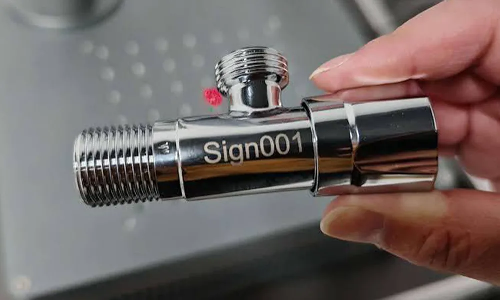
Failure Modes
Where Does Fastener Laser Marking Commonly Fail?
Failure diagnosis should separate a laser-process problem from a surface, positioning, data or production-flow problem. Correcting the wrong cause can make a visually acceptable sample less repeatable.
| Observed failure | Check first | Likely process implication | Verify after correction |
|---|---|---|---|
| Mark is light or changes from part to part | Surface finish, contamination, coating variation, focus height and recipe | Process window may be too narrow for real part variation | Repeat across representative surfaces and cavities |
| Mark breaks through zinc or plating | Layer stack, permitted stopping layer, pulse overlap and pass count | Energy removal exceeds the allowed surface change | Inspect layer condition and perform the required corrosion/functional check |
| Halo, tint or rough edge appears | Heat accumulation, overlap, cleaning state and repeated passes | Thermal or ablation margin is too aggressive | Compare appearance and surface integrity after cleaning |
| Mark shifts toward recess, edge or bearing zone | Datum, seating, cavity tolerance and orientation | Positioning error is larger than the allowed mark-zone margin | Run a representative batch and measure location repeatability |
| One nut flat is marked inconsistently | Angular orientation and indexing method | The correct face is not presented repeatably | Confirm selected-flat orientation over repeated loading |
| Small part moves during marking | Nest support, clamping, vibration and part seating | Workholding cannot maintain the datum through the mark cycle | Check position and focus after repeated loading |
| Data Matrix reads inconsistently | Cell size, contrast, quiet zone, focus, lighting and placement | Optical result or inspection setup lacks margin | Use the intended reader/verifier and production lighting |
| Serials are missing or duplicated | Data source, sequence rule, reject/rework path and recipe permissions | Traceability logic is not tied correctly to part flow | Run a controlled sequence with rejects and rework |
| Output misses takt | Load, locate, mark, inspect, reject and unload time separately | The bottleneck may be handling or inspection rather than laser power | Time the complete cycle under representative production conditions |
Production Workflow
How Does a Fastener Marking Process Move Into Production?
A production-ready process controls the part, the data and the inspection result from loading through release. The exact automation level depends on volume and variation, but the control sequence should stay explicit.
Load, separate and identify
Present one correct fastener to each nest or controlled position without overlap or mix-up, then select the correct program, data source and acceptance method for that part family and surface.
Orient, locate and mark
Establish the required face, angular orientation, XY datum and focus height, then run the approved laser recipe without entering protected areas or exceeding the allowed surface change.
Verify, reject or release
Check content, position, readability, code result and any in-line acceptance item. Separate failed parts, control rework and prevent an unverified fastener from re-entering the accepted flow.
Record, unload and change over
Store required result data, complete the batch count and unload accepted parts. Before the next size, finish or variant starts, reconfirm fixture, recipe, focus and data rules.
Sample Acceptance
How Should Fastener Samples Be Validated?
One attractive hand-held sample is not enough. Use representative finished parts, repeat the real loading condition and apply the same acceptance logic that will matter in production.
Define representative samples and protected zones
Include the real size range, head styles, nut sizes, material grades, coatings and surface states. Record the approved marking face, datum, keep-out regions and any thread, bearing, drive or contact surface that must remain unaffected.
Screen the laser process under real loading conditions
Change one meaningful parameter group at a time and record the source, optics, recipe, mark result and surface response. Repeat through the real nest, cavity, orientation or feed positions so fixture and focus variation are included.
Apply mark, surface and durability acceptance
Confirm fixed or variable data, mark position, human readability and machine-readable code result where required. Inspect for unacceptable breakthrough, roughness, tint, burr, residue or functional-area change, and run any wear, cleaning, corrosion or service test required by the drawing or quality plan.
Prove the full production cycle
Run enough representative parts to confirm loading, marking, verification, reject handling, batch control and takt before the final configuration and process revision are frozen.
Appearance is not enough for plated or functional fasteners
If the mark may alter corrosion protection, plating, a bearing/contact area or another controlled feature, the responsible customer or project quality requirement must define the applicable functional test. A clean-looking mark does not prove the surface still meets that requirement.
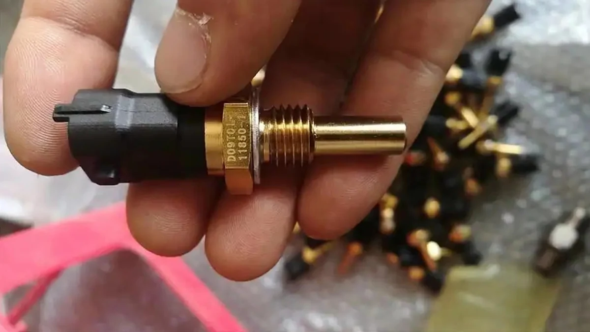
Evidence Record
What a qualified fastener sample record should contain
- Sample identityPart number, fastener family, material grade and actual finish/plating.
- Approved mark zoneDrawing reference, face, datum and keep-out limits.
- Laser setupSource family/model, lens/field, recipe ID and focus reference.
- Fixture & batchNest/cavity identity, orientation method, batch quantity and takt condition.
- Acceptance resultContent, position, readability/code result and surface-integrity observations.
- Functional testCorrosion, wear or other specified test when the project requires it.
- Evidence filesBefore/after photos, inspection records and relevant report reference.
- Technical sign-offNamed responsible reviewer, date and approved configuration/revision.
Final Configuration
How Do Sample-Test Results Determine the Final Machine Configuration?
The final machine is not selected from the word “fastener.” It is selected from the process window proven on real parts plus the geometry, batch presentation, takt, inspection and data requirements.
| What the test or production review shows | Configuration decision it influences | Why it matters |
|---|---|---|
| Which source and pulse behavior produces the accepted mark | Laser source family and pulse-control capability | The source must reproduce the required contrast, removal or engraving without exceeding the permitted surface change. |
| Smallest text/code feature plus total mark area | Lens, marking field and optical setup | Feature size and field size must be balanced so detail remains readable across the actual part range. |
| Height variation exceeds the fixed focus margin | Z control, focus strategy or 3D capability where justified | The surface must remain inside the usable process window across head styles and part seating variation. |
| Side or circumferential content cannot be reached from one fixed angle | Rotary/indexing axis, chuck or dedicated orientation fixture | Controlled angular motion is required when the mark extends beyond a stable tangent or one specific face must be presented. |
| Part placement varies beyond fixture tolerance | Improved nest/fixture or vision positioning | The system must correct the real source of position variation before the mark can repeat reliably. |
| Multi-cavity tray or large batch is required | Fixture pitch, field coverage, stage motion or multi-station layout | The optical field and handling method must cover every cavity without sacrificing focus or takt. |
| Manual loading cannot meet required output | Shuttle table, feeder, conveyor, robot or another automatic handling method | Automation is justified by the measured cycle and loading requirement, not by fastener type alone. |
| Serial or code data changes per part | Software, scanner, PLC, database or MES interface | Data selection and verification must stay synchronized with the correct physical part. |
| Automatic code/mark verification is required | Reader, verifier, camera and reject logic | Inspection hardware must match the same acceptance method used during validation. |
| Coating/plating limits the process margin | Source/pulse control, recipe protection and surface-specific parameter set | The approved configuration must preserve the allowed stopping layer and repeat the result across finish variation. |
| Full cycle misses takt although the mark itself is fast | Handling, inspection, parallelization or automation changes before simply increasing laser power | The bottleneck must be removed where it actually occurs. |
| Production schedule requires sustained operation | Duty-cycle margin, workstation design and thermal-management provision appropriate to the selected source | A short sample run does not prove the final system can support the planned operating pattern. |
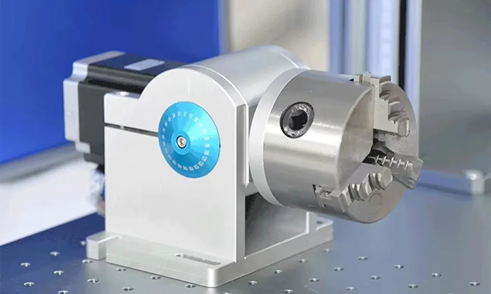
Configuration logic
Material and surface + required mark + target result + protected zones + geometry and loading + quantity/takt + sample acceptance together determine the source, optics, fixture, motion, automation, inspection, data and workstation configuration.
Further Technical Guidance
Related Material and Production Guidance
Once the fastener requirement is clear, use the relevant material guidance for surface behavior and the Solutions hub for positioning, rotary, automation or traceability method selection.
Steel Fasteners
Review steel-specific surface condition, contrast and engraving considerations.
Steel laser markingStainless Steel Fasteners
Review stainless-specific finish, contrast and heat-sensitive surface requirements.
Stainless steel laser markingGalvanized / Zinc-Coated Fasteners
Review zinc-layer change, breakthrough and corrosion-risk questions on the coating route.
Galvanized steel markingNickel, Chrome & Other Plating
Review plating stack, permitted stopping layer and functional/corrosion acceptance.
Plated metal laser markingPositioning, rotary, automation and traceability
For variable placement, selected-side or circumferential marking, high-volume handling, code verification or data integration, review the Laser Marking Solutions hub and match the production method to the measured fastener constraint.
Next Step
Evaluate Your Fastener Batch With Real Parts
Send the fastener family, material and finish, approved marking face, protected zones, mark content, target result, quantity, takt, loading method and acceptance tests. Zhuorui Laser can use representative sample testing to narrow the laser route and define the required optics, fixture, motion, inspection, data and automation configuration.