
Metal and Plastic Nameplates · Variable Data · Sample Validation
Industrial Nameplate Marking
Plan laser marking for equipment nameplates, rating plates, asset tags and identification plates by defining the actual substrate and surface, required mark content, plate geometry, production method and acceptance criteria before selecting the final laser marking configuration.
Nameplate / Workpiece Scope
What Nameplate Construction and Workpiece Conditions Need to Be Defined?
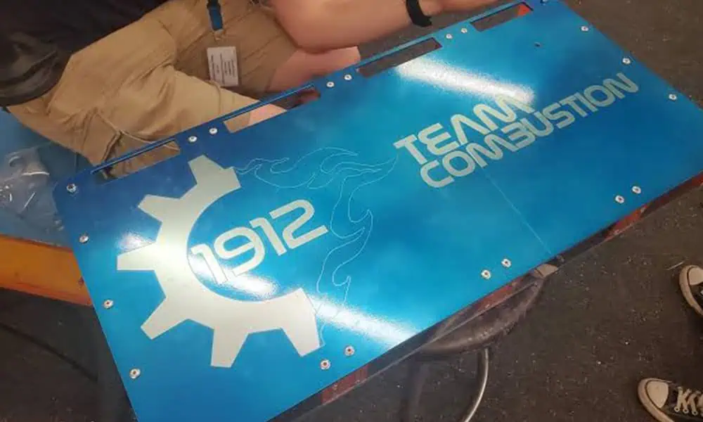
Typical applications include rating and identification plates attached to machinery, motors, electrical equipment, control cabinets and other industrial equipment. Start with the actual nameplate construction rather than the word “nameplate” alone: substrate, surface layer and the condition in which the plate reaches the marking station can all change the process.
Metal substrate with a defined surface condition
Aluminum, stainless steel and other metal plates may be bare, anodized, painted, powder-coated, plated or otherwise finished. The visible top layer can be as important as the underlying metal.
- Confirm alloy or supplier material when available
- Record anodizing, coating, paint or finish
- State whether the target is surface marking, controlled removal or engraving
Plastic resin, color and surface construction matter
Plastic nameplates can react very differently according to resin, pigment, filler, laser additive, coating and laminate construction. Appearance alone is not enough to select the laser.
- Provide resin or supplier grade when known
- Record color, additives, coating and laminate layers
- Identify nearby adhesive or heat-sensitive construction
Sheet, cut plate, assembled plate or installed nameplate
Marking may occur before cutting, after cutting, after adhesive application, after riveting or after installation on equipment. Each stage changes access, positioning and handling.
- Plate width, height and thickness
- Flatness, bending, holes, edges and usable marking zone
- Loose plate, strip, tray, fixture or installed-equipment loading
Why Mark
Why Are Industrial Nameplates Marked?
The reason for marking determines what information matters, how long it must remain readable and how the result should be tested.
Identify the equipment and its rated information
Product names, models, electrical ratings, capacities and other fixed technical information help distinguish equipment and communicate approved product data.
Connect each plate to production and lifecycle records
Serial numbers, batches, dates and machine-readable codes can connect the physical product to manufacturing, service or asset records when the data workflow is controlled.
Keep warnings and service information available
Nameplates may carry operating information, warnings, maintenance references and other text that must remain legible for the required service environment.
Marking Content
What Information Is Usually Marked on an Industrial Nameplate?
| Nameplate content | Production purpose | Input required | Acceptance check |
|---|---|---|---|
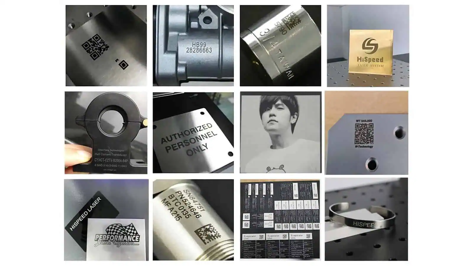
| Brand, product name and model | Equipment identity | Approved artwork, font, mark size and location | Appearance, placement and consistency |
| Voltage, power, capacity or rating data | Technical identification | Field list, units, revision control and minimum character size | Correct values and legibility |
| Serial number, date and batch | Manufacturing traceability | Data source, format, sequence and duplicate-control rule | Correct data and record association |
| QR or Data Matrix code | Digital lookup and lifecycle records | Code content, size, quiet zone, scanner and grade target if required | Readability under the defined inspection condition |
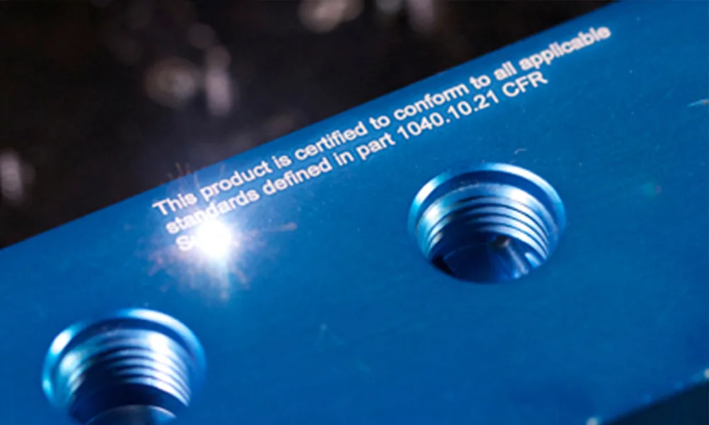
| Warning, compliance or service text | Use, maintenance and product information | Approved wording, language, revision and required service condition | Text completeness and retained readability |
Result Variables
What Determines the Laser Marking Result?
The result is not determined by the nameplate category alone. Material, surface construction, layout, geometry, environment, data workflow and production speed must be evaluated together.
| Variable | What to define | Why it changes the result |
|---|---|---|
| Base substrate | Metal alloy, plastic resin or known supplier grade | Different substrates absorb laser energy differently and may produce different contrast, depth, texture and thermal response. |
| Surface construction | Anodizing, paint, powder coating, plating, laminate, pigment or additive | The visible mark may be created primarily in the top layer rather than in the underlying substrate. |
| Target mark | Dark mark, light mark, coating removal, shallow engraving, fine text or code | Different effects can require different laser wavelengths, pulse characteristics and process windows. |
| Layout | Character size, line width, code size, quiet zone and usable mark area | Fine characters and small code cells demand tighter control of focus, line definition and positioning. |
| Geometry | Plate dimensions, thickness, flatness, holes, edges, datum and installed condition | Geometry controls access, focus consistency, fixture design and repeatable mark placement. |
| Environment | Indoor or outdoor use, cleaning, chemicals, oil, abrasion and temperature exposure | A visually good initial mark may still fail the required service or cleaning condition. |
| Data workflow | Fixed fields, variable fields, source, sequence, duplicate control and verification | A good physical mark is not acceptable if the wrong serial number, batch or code is assigned to the plate. |
| Throughput | Batch size, takt time, loading method and changeover frequency | A process that works on one sample must also meet the required production rate without losing mark quality. |
Target Result
What Should an Acceptable Nameplate Mark Achieve?
Define acceptance before choosing the machine. “Looks good” is not enough when the plate also carries variable data, machine-readable codes or durability requirements.
- Contrast & appearanceDefine the required dark/light effect, consistency and acceptable surface texture.
- Fine-text legibilitySet the minimum character size, line width and any critical symbols that must remain clear.
- Code readabilityDefine code type, size, quiet zone, intended scanner and any project-specific verification target.
- PositionSet the datum, usable marking zone and permitted tolerance relative to edges, holes or other reference features.
- Surface integrityDecide whether coating removal, engraving, discoloration, melting or visible heat effect is acceptable.
- Data correctnessRequire serial, batch, model, date and encoded content to agree with the approved source and production record.
- DurabilityDefine the cleaning, wear, chemical, temperature or outdoor exposure the mark must survive when those conditions apply.
- Production resultRequire the accepted quality to remain reproducible at the representative batch size, takt time and changeover condition.
Geometry & Handling
How Do Plate Geometry, Holes, Edges and Loading Affect Marking?
Define the usable area before testing the layout
Record plate width, height, thickness, flatness and the position of holes, slots, bends and edges. The marking zone should be defined relative to stable reference features.
- Distance from holes and plate edges
- Keep-out areas around mounting or formed features
- Maximum and minimum plate variants
Repeatable loading matters as much as the artwork
If the operator can place the plate differently each cycle, even a stable laser process can produce position errors.
- Define datum features and orientation
- Confirm whether one fixture handles multiple variants
- Decide whether additional position verification is required
Loose, tray-loaded and installed plates require different handling
Marking a flat loose plate is different from marking a riveted or installed plate on finished equipment. Access, loading time and focus control should be tested in the actual production state.
- Single plate, strip, tray or finished equipment
- Manual, semi-automatic or line-side loading
- Required changeover time between plate variants
First-Test Laser Route
Which Laser Route Should Be Tested First?
Use the table as a first-test direction rather than a universal material rule. The actual surface construction and required result still need to be confirmed on representative plates.
| Workpiece / target | Useful first-test direction | Why start there | When to compare another route |
|---|---|---|---|
| Bare stainless steel, steel or other directly marked metal | Fiber laser | Fiber is a practical starting route for direct marking and engraving on many industrial metals. | Compare MOPA fiber when the target requires tighter pulse control, a different dark-mark response or a narrower thermal process window. |
| Natural anodized aluminum with a dark or black target | MOPA fiber | Adjustable pulse characteristics provide an important additional control variable when developing dark marks on anodized aluminum. | Compare another fiber process if a light or removal-type mark is acceptable instead of a dark result. |
| Colored anodized or coated metal where the mark is created mainly by controlled top-layer change or removal | Fiber / CO₂ screening | The relevant interaction may occur mainly in the coating or pigment rather than in the base metal. | Compare both routes when coating absorption, edge quality, removal depth or substrate exposure is uncertain. |
| Heat-sensitive plastic, fine text or small machine-readable code | UV laser | UV is a strong first route when the goal is fine marking with reduced thermal deformation on suitable plastics. | Compare 1064 nm or CO₂ when the actual resin, pigment or laser additive responds better to those wavelengths. |
| Laserable plastic laminate or plastic construction designed for surface engraving | CO₂ laser | CO₂ can be effective when the material construction is intended to respond through surface engraving or layer removal. | Compare UV or another route when detail, heat effect or the actual supplier material requires a different process. |
| Unknown plastic, unknown coating or mixed supplier lots | Identify and sample first | Visual appearance alone does not establish resin, coating chemistry or laser absorption. | Screen the relevant laser routes only after the actual material and required mark effect are defined. |
Failure Diagnosis
Common Industrial Nameplate Marking Failure Modes
The visible symptom is useful only when it leads to the correct next check. Avoid correcting every defect by simply increasing laser power.
| Observed problem | Variables to check first | Useful next action |
|---|---|---|
| Low or uneven contrast | Surface finish, coating thickness, focus, material lot, process window | Compare representative areas and supplier lots before changing the complete machine configuration. |
| Burn halo or excessive discoloration | Energy input, pulse behavior, scan strategy, coating thickness and heat accumulation | Reduce unnecessary thermal input and compare a process route better suited to the required surface effect. |
| Plastic melting, raised edges or deformation | Resin, pigment, heat sensitivity, energy density and repeated passes | Check whether a lower-thermal-impact route such as UV should be included in the next sample matrix. |
| Fine text loses definition | Character size, line spacing, focus, field size and process energy | Test the real minimum text and line width rather than approving only a large logo sample. |
| QR or Data Matrix scans inconsistently | Cell definition, code size, quiet zone, contrast, reflection, distortion and scanner setup | Test with the intended reader and record the exact code layout and process condition that passes. |
| Mark position shifts around holes or edges | Plate tolerance, datum selection, fixture repeatability and operator loading | Separate laser-process repeatability from workpiece-positioning error before changing marking parameters. |
| Different lots produce different appearance | Alloy, resin, pigment, additive, coating formulation or thickness | Mark retained samples from each meaningful supplier or material variant and compare the available process window. |
| Correct-looking mark but wrong serial or code | Data source, sequence, operator entry, duplicate control and record association | Correct the data workflow rather than treating the problem as a laser-quality defect. |
| Sample quality passes but cycle time is too long | Mark content, process time, field size, loading, verification and changeover | Measure the complete production cycle and optimize process and handling together. |
Production Workflow
How Does Variable-Data Nameplate Marking Enter Production?
Variable-data marking is not only a laser task. Data selection, workpiece positioning, verification and production records must remain connected to the physical mark.
1. Load and identify the plate
Confirm plate type, orientation, material variant and the correct production job before marking.
2. Select the recipe and data
Load the approved layout and retrieve or enter serial, batch, date, rating or code data from the defined source.
3. Position the workpiece
Locate the plate against the defined datum and confirm that the real marking zone is accessible.
4. Mark the plate
Apply the validated process recipe without mixing parameters between incompatible plate or surface variants.
5. Verify the result
Check the required combination of appearance, position, text, machine-readable code and data correctness.
6. Accept, reject and record
Define what happens to failed plates, how rework is controlled and which production or traceability record is retained.
Sample Acceptance
How Should Industrial Nameplate Samples Be Tested and Accepted?
Use the target-result criteria above as the pass/fail standard, then validate them through a controlled sample process. Test the actual construction and the hardest meaningful production conditions rather than approving a generic demonstration mark.
- Build a representative sample set
Include the actual substrate and surface variants that can realistically change the result: relevant colors, coatings, supplier lots, minimum feature sizes and difficult hole/edge geometry.
- Freeze the real artwork and variable data
Use the production layout, actual minimum text, serial/batch examples and the real QR or Data Matrix content instead of approving only a large logo or simplified test file.
- Define a limited process matrix
Start from the relevant first-test laser route and compare only the process windows needed to distinguish wavelength, pulse behavior or surface-response differences.
- Inspect the marked samples
Check the criteria already defined for contrast, fine text, code readability, mark position, surface integrity and data correctness, and record which process condition produced each result.
- Run the required exposure test
When the application requires it, apply the agreed cleaning, rubbing, chemical, oil, temperature or outdoor exposure to representative accepted samples.
- Reinspect after exposure
Repeat the relevant visual, dimensional or scanner checks after the exposure test rather than assuming the initial appearance proves durability.
- Check production repeatability
Run a representative batch with the intended loading method, positioning, data changes and changeover condition to confirm that quality and cycle time remain acceptable.
- Record the accepted process
Link the accepted material/surface variant to the approved recipe, verification method, pass/fail result and any handling or data-control condition that must be reproduced in production.
Final Machine Configuration
How Do Sample-Test Results Determine the Final Machine Configuration?
The purpose of sample testing is not merely to prove that a laser can make a visible mark. Testing should identify a process window that meets mark quality, data, durability and production requirements, then define the hardware and workflow needed to reproduce it.
| What the sample test reveals | Configuration decision it informs |
|---|---|
| Which wavelength and pulse behavior produce the required mark without unacceptable surface damage | Laser family and, where relevant, fiber versus MOPA-fiber direction and usable process window |
| Smallest text, line or Data Matrix feature that must remain clear | Optical field size, focusing requirement and marking-field choice |
| Whether mark quality changes with height, flatness or installed condition | Z-axis strategy, work height control and fixture requirement |
| Whether position changes with plate tolerance, holes or operator loading | Datum strategy, fixture design and whether vision-based position verification should be evaluated |
| Number of plate sizes and how often the job changes | Fixture changeover method, recipe management and operator workflow |
| Where serial numbers, batches and codes originate | Software workflow and required scanner, file, PLC or database communication |
| Whether codes or mark positions must be automatically verified | Code reader, camera or other verification method and reject handling |
| Whether the accepted process meets takt time under real loading conditions | Process optimization, laser configuration, loading method and degree of automation; higher laser power is not automatically the correct solution |
| Whether supplier, color or coating variants narrow the acceptable process window | Recipe control, material segregation and the number of validated parameter sets required for production |
Related Technical Guides
Review Material and Machine Details After the Application Is Defined
Check the actual substrate and surface
Use the relevant material guide when you need more detail about how the real metal or plastic responds to laser energy.
Compare equipment only after the marking task is clear
Machine-family information becomes more useful after the substrate, surface, target result, geometry, variable data and sample acceptance requirements have been defined.
Next Step
Evaluate Your Industrial Nameplate Marking Requirement
Share the actual nameplate construction, required mark content, geometry, variable-data workflow, production rate and acceptance criteria. Zhuorui Laser can use representative sample testing to compare the relevant laser route and determine the configuration needed to reproduce the accepted result.
Prepare: plate photos or samples; alloy or plastic resin; anodizing, coating, paint or color; final artwork; fixed and variable fields; QR or Data Matrix requirement; scanner requirement; dimensions, thickness, holes, edges and datum; batch size and takt time; loading method; required durability test; destination and voltage.