
Industrial Parts · Curved Surfaces · Traceability
Valve and Fitting Marking
Plan laser marking for valve bodies, pipe fittings, adapters and related industrial parts by defining the part surface, mark content, geometry, positioning method, production rate and acceptance criteria before final machine selection.
- Curved, rough and recessed marking zones
- Part, batch, heat and certificate references
- Sample-test results tied to final configuration
Workpiece Scope
Start with the actual valve or fitting workpiece
Valve and fitting projects can look similar by product name but behave very differently at the marking zone. Define the part family, surface state and usable marking area before choosing a test route.
Cast, forged or machined bodies
Record the body variant, marked location, accessible faces and production stage. An as-cast body can present rough texture, scale, pores or uneven reflectivity that reduce edge clarity and code contrast, while a machined pad usually gives a more uniform reference surface and more repeatable positioning.
- Model, size or customer-specified identification
- Serial, batch, heat or lot reference
- Mark location that avoids restricted functional surfaces
Adapters, elbows and couplings
Fittings may combine small diameters, shoulders, threads and limited sight lines. Confirm the actual radius, available mark length, orientation and datum rather than assuming a flat test coupon represents the finished part.
- Outer circumference, face, shoulder or wrenching area
- Controlled direction for text or machine-readable codes
- Readable result after defined handling and cleaning
Manifolds and compact assemblies
Where several ports or faces sit close together, each mark position may need its own access, focus and fixture check. Multi-face work should be evaluated as a handling and positioning problem as well as a laser-process problem.
- Multiple faces and restricted optical access
- Part-to-record association
- Fixture and changeover requirements for each variant
Why Mark
Why are valves and fittings marked?
The marking task normally exists to identify the part, connect it to manufacturing records, support installation or service, or carry variable traceability data. Define that purpose before deciding what the mark should look like.
Part and variant recognition
Model, size, rating, logo, orientation or customer-specific identifiers help distinguish parts during assembly, inventory, installation and service.
Link the part to a manufacturing record
Serial, batch, heat or lot references can connect a physical component with production, inspection or material records when the data workflow is controlled.
Keep essential identification on the component
Flow direction, assembly identifiers and service references can remain available after packaging is removed and the part enters the field.
Support scanning and record retrieval
QR or Data Matrix codes can support lookup and inspection workflows when code size, surface condition, geometry, reader and data association are validated together.
What Is Marked
Turn identification requirements into a testable marking brief
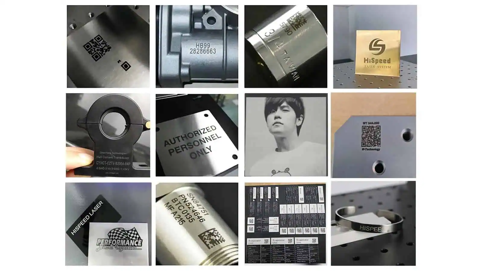
Use the customer drawing, work instruction or traceability process as the source of truth. Define the exact content, size, position, data source and acceptance method before sample testing.
| Mark content | Typical purpose | Inputs before testing | Acceptance check |
|---|---|---|---|
| Brand, logo or model | Part identity and variant recognition | Artwork, dimensions, location, orientation and visual target | Appearance, placement and repeatability |
| Size, rating or customer-specified designation | Product or configuration identification | Exact text, character height, datum and drawing tolerance | Legibility and correct association with the part variant |
| Serial or batch code | Production and service traceability | Data source, numbering rule, duplicate control and record link | Correct data, position and record match |
| Heat, lot or material-certificate reference | Material and production record lookup | Reference format, update workflow and required permanence | Readable mark and reliable association with the supplied record |
| QR or Data Matrix code | Digital lookup or inspection workflow | Code size, reader, quiet zone, contrast target and geometry | Readability on representative parts and after defined handling tests |
| Flow arrow or assembly identifier | Orientation and installation guidance | Drawing location, direction and surface restrictions | Correct direction, placement and no unacceptable functional impact |

Result Variables
What determines the laser marking result?
The nominal part name is not enough. Mark quality depends on the actual surface, required result, geometry, positioning repeatability and production data flow working together.
Base material, finish and contamination
Alloy, plating, coating, oxide, passivation, as-cast texture, machining marks, oil, coolant and scale can change absorption, contrast, edge quality and repeatability.
Content, size and visual target
Small text, fine Data Matrix modules, shallow contrast marks and deeper engraving do not use the same acceptance criteria or process window.
Radius, focus and datum control
Curvature, recess depth, port layout, marked length, working distance and fixture repeatability determine whether the complete mark remains in a usable optical and positional window.
Rate, variants and data timing
Batch size, takt, changeover frequency, variable-data arrival, reader checks and reject handling can make a process unsuitable for production even when one sample looks good.
Target Result
What Should an Acceptable Valve or Fitting Mark Achieve?
A good-looking sample is not enough. The target should combine data correctness, readability, placement, durability and protection of the part’s functional surfaces.
Correct information
The marked text or code must match the released serial, batch, heat, lot or certificate reference for that specific part or production lot.
Correct location and orientation
Placement should follow the drawing or work instruction and remain repeatable across actual part variants and loading conditions.
Readable by the intended method
Text should remain legible and machine-readable codes should be checked with the intended reader on representative surfaces and viewing geometry.
Appropriate contrast or depth
Define whether the requirement is visual contrast, shallow engraving, deeper removal or another controlled effect instead of assuming that more depth is always better.
Stable after defined exposure
Where required, test the mark after specified cleaning, rubbing, oil exposure, handling or other project-defined conditions.
No unacceptable impact on critical surfaces
Do not select threads, sealing faces, mating surfaces or other pressure- or function-critical areas for marking unless the drawing, work instruction or responsible engineering or quality authority permits it.
Geometry, Positioning & Handling
How do shape and part presentation change the marking task?
Valve and fitting geometry can change focus, optical access and positional repeatability. The important question is not only where the mark fits, but whether the complete mark stays inside a stable processing window during real loading.
Machined flats
A flat pad usually simplifies focus and fixture repeatability, but available area, edge distance, surface residue and mark orientation still need to be controlled.
Curved bodies
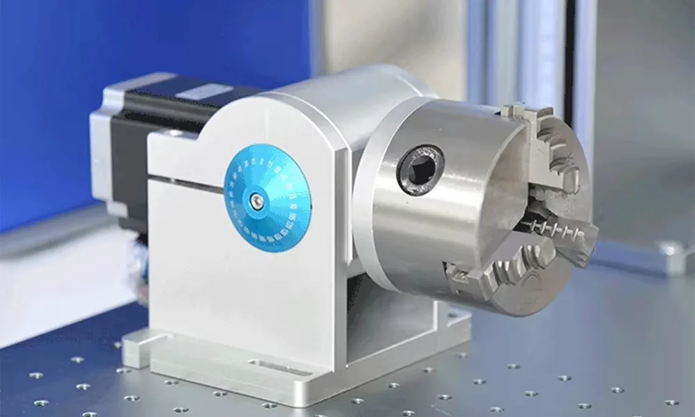
As the mark spans more curvature, different parts of the graphic can move away from the best focus and change line width or code readability. Radius and mark length should be tested together.
Ports, threads and shoulders
Restricted sight lines and nearby functional features can limit where the beam can reach and where the part can be safely marked. Actual access and fixture interference must be checked on the real component.
Recessed or multi-face areas
Deep pockets, ribs, adjacent ports and multiple faces can require separate positions, different datums or controlled part motion. One setup should not be assumed to cover every face or variant.
First-Test Laser Route
Which laser route should be tested first?
Use the first test to narrow the process window, not to declare one source universal. Start from the real material and surface, then compare pulse control, geometry and handling only where the sample result shows a reason to do so.
| Starting condition | First comparison | Why start there | Escalate or compare when |
|---|---|---|---|
| Bare metallic valve or fitting surface | 1064 nm fiber route | It is a common starting route for metal identification, contrast marking and engraving trials and provides a practical baseline on the actual part. | Contrast, heat input, cycle time, depth or surface condition cannot be balanced inside the required window. |
| Fine code, controlled dark mark or heat-sensitive finish on a metal part | MOPA fiber comparison | MOPA remains a fiber-laser route but adds wider pulse-width control, which can be useful when the process needs finer control of how energy is delivered. | Pulse control still cannot meet the visual, thermal or throughput target on the representative surface. |
| Painted, plated, coated or otherwise layered surface | Test the top-layer objective before choosing the final source | The task may be to modify the coating, remove it, expose the substrate or avoid substrate damage. The base metal alone does not define the correct process. | The first route damages the substrate, creates an unacceptable edge, leaves poor contrast or behaves inconsistently across coating variation. |
| Long curved span, deep recess or multi-face requirement | Keep the laser-source test and the motion/focus test separate | A good source result on one point does not prove the whole graphic can stay in focus or in view across the production geometry. | The mark changes across the radius, access is blocked, or positional repeatability is not stable enough for the required content. |
Failure Modes
Common valve and fitting marking failures and what to check first
Diagnose the visible symptom before changing parameters. Many apparent “laser problems” are actually surface, geometry, fixture or data-association problems.
| Observed problem | Likely variables to separate | First checks |
|---|---|---|
| Broken or uneven characters on an as-cast surface | Surface roughness, scale, contamination, mark size, local focus | Compare rough and machined areas, clean consistently, inspect whether the smallest strokes or code modules are too small for the actual texture. |
| One side of a curved mark is sharp and the other is weak | Focus variation, radius, mark span, part angle | Measure the marked span against curvature and test whether a shorter field, adjusted presentation or controlled motion improves consistency. |
| Data Matrix is visible but reads inconsistently | Module size, contrast, surface texture, curvature, reader angle | Use the intended reader, representative parts and real viewing geometry; separate code-design limits from laser-process limits. |
| Different parts show different depth or contrast | Surface state, residue, fixture datum, focus repeatability, part variation | Record the exact part condition and loaded position, then compare whether the variation follows the surface or the fixture. |
| Mark position shifts between variants | Datum choice, fixture changeover, wrong program or orientation | Verify part identification, fixture reference, recipe selection and mark-position check before changing laser parameters. |
| Recessed area is incomplete or distorted | Optical access, recess depth, adjacent ports, working distance | Check line of sight and clearance on the real part; confirm the beam can reach the whole graphic without fixture or geometry interference. |
| Mark looks acceptable but traceability is wrong | Variable-data source, duplicate control, part-to-record association | Confirm that the serial, batch, heat, lot or certificate reference belongs to the specific part being marked. A visually perfect mark with the wrong data is still a failed process. |
Production Workflow
How does a successful sample become a repeatable production process?
Production adds loading, positioning, recipe selection, variable-data control, verification and reject handling. Each step should preserve the link between the physical part and the record that the mark represents.
Identify the part and variant
Confirm model, size, material or surface state and the required marking zone before loading.
Load and locate
Place the part against a defined datum, confirm orientation and ensure the full mark area is optically accessible.
Select the approved recipe
Use the validated parameter set, focus condition and position for that part family instead of relying on operator memory.
Receive the correct data
Release the serial, batch, heat, lot or certificate reference for the specific part or lot and apply duplicate-control rules where required.
Mark the defined zone
Run the approved process without moving the mark onto a different surface or changing the geometry assumptions used during testing.
Verify the result
Check content, position, visual quality and machine-readable codes using the project-defined inspection method.
Accept or reject
Separate parts that fail content, position, readability or surface criteria instead of allowing visual appearance alone to release them.
Close the traceability record
Store or confirm the required part-to-record association so the physical mark and the production or certificate reference remain linked.
Sample Acceptance
Approve the result on representative valve and fitting samples
Use real production surfaces and include the difficult limiting conditions that could change the result. Acceptance should cover mark quality, data correctness, location and the intended use conditions.
Freeze the representative part set
Include the actual alloys, coatings, rough as-cast conditions, machined areas, smallest usable mark zones, strongest curvature and other relevant part variants.
Freeze the real data and position
Supply artwork, text, variable-data rules, code format, certificate-reference structure, drawing location and position tolerance.
Test the intended use case
Review contrast or depth, legibility, code reading, position, edge condition and any defined cleaning, rubbing, oil or handling exposure.
Record the approved window
Keep the accepted sample, settings, focus or motion condition, inspection result and part-to-record association as the basis for production release and final configuration.
Final Machine Configuration
How do sample-test results determine the final machine configuration?
The final configuration should follow the proven process window. Laser source, optics, fixture, motion, inspection and software are selected from what the representative samples and production workflow actually require.
| Sample-test finding | Configuration decision it informs |
|---|---|
| Required contrast or depth is stable on the representative surface | Confirms the laser-source and pulse-control route that should become the production baseline. |
| Quality changes when the mark spans curvature | Triggers evaluation of working distance, field size, controlled rotation, multi-position marking or another focus-management method. |
| Different valve sizes cannot repeat the same position | Defines fixture, datum, adjustable positioning or vision requirements and the needed changeover method. |
| Small text or Data Matrix becomes sensitive to field position | Links lens choice, marking field, working distance and code size to the actual readability target. |
| Quality is acceptable but cycle time misses the production target | Requires another balance of source capability, passes, process window, loading method and automation before release. |
| Variable-data or record association creates risk | Defines software interface, recipe control, scanner or verification needs and how reject handling should work. |
| Manual loading creates unacceptable positional variation | Supports a stronger fixture, controlled part presentation, vision positioning or a more automated cell depending on the required rate and variation. |
Next Steps
Start a valve and fitting marking review
Send the part family, real surface state, marked zone, data requirements, production rate and representative samples. Zhuorui Laser can then compare the first test route and build the final configuration around the validated result and production workflow.
Prepare: material and surface state · product photos or drawings · marking content and size · target effect · production rate · automation or data needs · voltage and destination · sample quantity.