
Powder-Coated Surface Guide
Powder-Coated Metal Marking
Laser marking on powder-coated steel or aluminum starts with the cured coating, not the metal name alone. The process may selectively remove the powder layer, change its appearance or expose the substrate, so coating condition, target mark, part geometry, safety controls and real-sample validation all matter before a laser marking machine is specified.
- Start with the coating: powder chemistry, cure, thickness, color, texture and adhesion.
- Define the mark: identification, code, logo, selective removal or exposed-metal contrast.
- Validate the final part: edge quality, readability, corrosion exposure, dust/fume and production fit.
Quick Answer
Can Powder-Coated Metal Be Laser Marked?
Powder-coated metal can often be screened for laser marking, but the mark may be made by removing or changing the powder layer rather than by marking bare steel or aluminum directly.
Record the powder type, cure state, thickness, color, gloss, texture, adhesion and metal substrate before choosing a source. A coating-removal mark can reveal fresh metal, change the part’s corrosion protection or leave an edge that fails a cosmetic requirement. If the target is a readable code, define the code size, scanner and verification method at the same time.
Practical rule: do not choose the machine from the metal name alone. First define the finished powder-coated stack and the accepted mark; then use sample testing to decide whether the process window is clean, repeatable and compatible with the part’s corrosion, cosmetic and readability requirements.
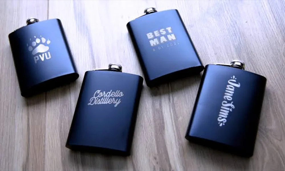
Surface Diagnosis
Identify the Complete Powder-Coated Surface Stack
Two parts can both be called powder-coated metal and still need different test directions. The laser response changes when the coating, cure, substrate or preparation changes.
Powder Type and Cure
Record thermoset family when known, such as polyester, epoxy or hybrid, plus cure schedule, recoat history and whether the coating is fully cured.
Uncured or partially cured material can soften, smear or generate a different residue from a production-finished surface.
Thickness and Adhesion
Coating thickness, edge build, adhesion and texture affect how selectively the layer can be removed without over-heating the substrate.
Measure or document the finish where a narrow line, small code or controlled removal window is required.
Color, Pigment and Gloss
Dark, light, metallic, textured and high-gloss powders can absorb and scatter energy differently.
Do not assume a result on one color transfers to another color, supplier formulation or gloss level.
Metal and Preparation
Steel, stainless steel, aluminum and other metals can be exposed after coating removal. Surface roughness, pretreatment and corrosion protection remain part of the stack.
The exposed substrate may need its own contrast, depth and corrosion test.
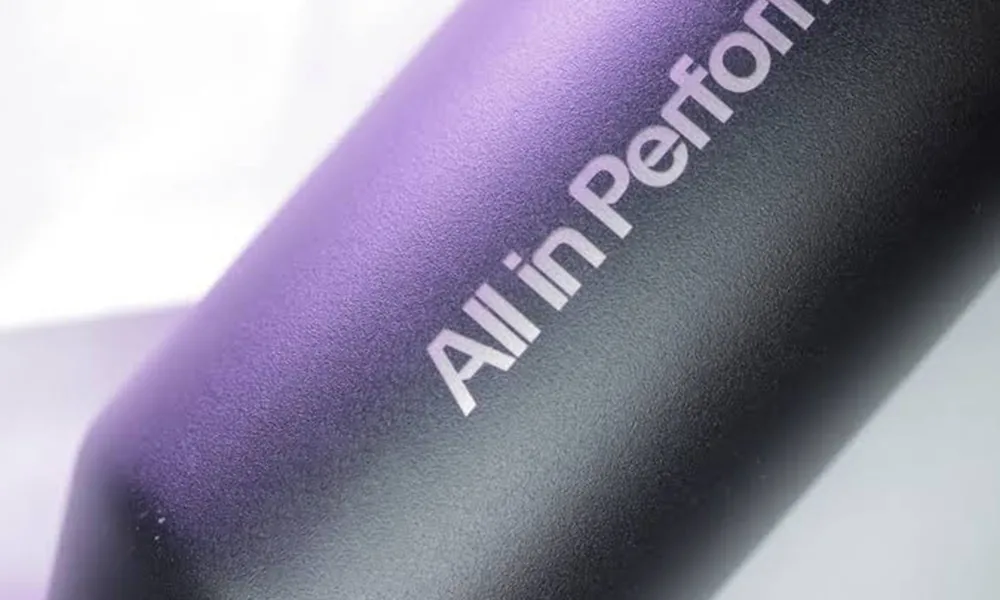
Related coating routes
Use the closest material route when your real surface is not powder coating alone: painted metal, anodized aluminum or plated metal.
Typical Parts and Marking Reasons
Where Are Powder-Coated Parts Used and Why Are They Marked?
Powder coating is common on durable metal parts that need corrosion protection, wear resistance or a finished appearance. Laser marking is usually added when the finished surface still needs permanent identification, traceability, machine-readable data or branding without applying a separate label.
Electrical Enclosures and Control Cabinets
Powder-coated steel or aluminum panels, doors and housings may need model information, serial identification, panel references or service traceability after coating.
Machine Housings, Guards and Frames
Industrial equipment parts may require part numbers, asset IDs, assembly references or maintenance identification that remains with the finished metal surface.
Automotive and Mobility Components
Powder-coated brackets, covers, housings and structural components may be marked for part identification, batch or serial traceability and downstream inspection.
Appliances, Tools and Durable Products
Finished metal products may use laser marking for model designation, logos, product identification or manufacturing traceability where adhesive labels are undesirable.
Why the application matters: the same coating can need a very different process window for a large cosmetic logo than for a small Data Matrix code. The product context defines mark size, viewing or scanning conditions, durability and acceptable surface change.
Marking Content
What Is Usually Marked on Powder-Coated Metal?
The content of the mark affects feature size, contrast, inspection method and the amount of coating that must be changed or removed. Define the information first so the sample test is built around the real production requirement.
Identification and Traceability
Part numbers, serial numbers, model IDs, batch or lot codes, date codes and asset identifiers are common when each finished component must be identified through production or service.
QR and Data Matrix Codes
Machine-readable codes need a defined module size, quiet zone, reader distance and acceptance method. Fine features make coating texture, residue, focus and contrast more critical.
Functional and Service Marking
Inspection IDs, assembly references, panel legends and maintenance information may prioritize legibility and durability over decorative appearance.
Branding and Cosmetic Graphics
Logos, product names and decorative windows usually place more emphasis on edge quality, uniform removal, viewing angle and batch-to-batch cosmetic consistency.
Mark content becomes an engineering input: character height, line width, code module size, mark area, edge clearance and required readability all influence the lens, process window, fixture and inspection method.
Mark Outcomes
Define What You Want the Laser to Change
“Marking” can mean layer removal, color change or a second operation on the exposed substrate. Naming the mechanism prevents a generic machine answer from being mistaken for a qualified process.
| Target outcome | What may change | Main risk or boundary | Validate on the final part |
|---|---|---|---|
| Selective powder removal | A controlled window exposes steel or aluminum under the coating. | Uneven thickness, residue, halo, edge lift or unwanted substrate heat. | Removal width, edge sharpness, cleanliness, exposed area and post-cleaning appearance. |
| Coating color or gloss change | The coating is modified without fully exposing the metal. | Color shift may vary with pigment, gloss, viewing angle and batch. | Uniformity, tactile feel, gloss, color difference and code readability if applicable. |
| Exposed-metal contrast | Coating removal creates contrast against the remaining powder layer. | Fresh metal may have different oxidation or corrosion behavior from the coated area. | Contrast after cleaning, handling, humidity, salt or downstream finishing. |
| Shallow substrate interaction | After removal, the laser also changes the underlying metal. | Depth, burr, heat tint and corrosion protection can exceed the accepted limit. | Depth, roughness, substrate integrity and functional drawing requirements. |
| QR or Data Matrix code | Fine removed lines or exposed substrate form a machine-readable code. | Coating texture, curvature, residue, reflectivity and low contrast can reduce reading or verification quality. | Reader pass at the defined distance; when a quality grade is required, verifier result using the specified method, lighting, module size, quiet zone and reject rule. |
| Decorative window or logo | Large-area coating removal or controlled color change creates a visual mark. | Cosmetic variation, edge softness and plume deposition can be visible. | Viewing distance, lighting, cleaning, scratch resistance and batch consistency. |
Reader and verifier are different acceptance tools: a reader confirms that a symbol can be decoded in a defined setup. A verifier evaluates symbol quality using a specified method and lighting geometry. Record which result is required; a successful reader test alone is not a DPM quality grade.
Do not promise a universal color or depth: coating supplier, powder chemistry, cure, substrate, scan strategy and cleaning can change the result. A good-looking coupon is not a production acceptance standard by itself.
Part Geometry and Size
How Do Part Shape, Coating Thickness and Size Change the Process?
The coating controls the first interaction, but geometry determines whether the beam stays in focus, whether the plume can be extracted cleanly and whether the accepted test result can be repeated on the actual part.
Coating Thickness and Edge Build
For selective removal, coating thickness is often more directly important than the base-metal thickness. Thick or uneven powder, edge build and textured finishes can require more passes or a wider process window and can increase residue or edge variation.
Curved or Cylindrical Surfaces
Curvature changes the distance and angle between the surface and the focused beam. A small mark may fit within the focal tolerance; a larger wraparound mark can require controlled rotation, 3D focus compensation or multiple indexed positions.
Thin Sheet and Low Thermal Mass
Thin panels can respond more quickly to local heat than heavy sections. When cosmetic flatness or nearby coatings are sensitive, verify discoloration, local distortion and substrate interaction rather than assuming the same settings will transfer from a thick coupon.
Large, Tall or Recessed Parts
Large housings, deep features and tall assemblies can limit field coverage, working distance, beam access, fixture clearance and extraction. The machine must accommodate the real envelope and marking position, not only the nominal mark size.
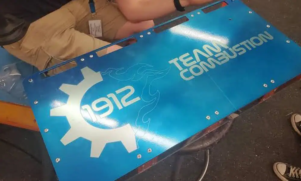
Geometry changes the equipment decision: part height and variation affect Z travel and focusing; round parts can require a rotary marking solution; random placement can justify vision positioning; large height variation may require a 3D or multi-position approach.
Laser Direction
Screen the Laser Against the Coating-Metal Stack
A 1064 nm fiber laser marking machine is often a practical first screening route when selective coating removal and exposed-metal contrast are the target. That starting point is conditional: the powder binder, pigment, color, texture and thickness can dominate absorption, while the newly exposed metal changes reflection and heat flow.
Source labels and wattage do not define the process window. Screening should compare pulse duration, pulse energy, peak and average power, repetition rate, scan speed, hatch spacing and pass count. Spot size, focus position and field lens affect fluence, line width and focal tolerance; changing one variable can alter edge quality, residue, substrate heat and cycle time.
MOPA fiber may be reviewed when adjustable pulse duration and repetition rate are useful for exploring a narrower removal window, but additional control does not guarantee lower heat, cleaner removal or a better code grade. UV and CO2 should be treated as separate routes: UV may be screened when coating absorption, fine detail or limited heat spread is important; CO2 may be screened when the organic coating responds strongly at its wavelength. In both cases, exposed-metal response, debris, beam delivery, speed and complete-machine support still require sample qualification.
If the accepted process also needs part rotation, camera alignment, height compensation, online handling or data integration, treat those as machine-configuration inputs after the coating response has been qualified.

| Route | Worth screening when | Boundary | Verify |
|---|---|---|---|
| 1064 nm fiber | Selective coating removal or exposed-metal contrast is the target on a compatible coating-metal stack. | Powder formulation can dominate absorption; exposed metal changes reflection and heat flow. Bare-metal settings do not transfer automatically. | Pulse energy and average power balance, spot/focus, removal selectivity, substrate heat, residue, line width, contrast and cycle time. |
| MOPA fiber | Adjustable pulse duration and repetition rate justify screening a wider process window for edge quality or substrate interaction. | More parameter control does not guarantee clean removal, lower heat, lower dust or better code grade. | Pulse duration, repetition rate, peak/average power balance, focus, repeatability, coating edge, exposed substrate and fume load. |
| UV | The coating response, fine-detail target or heat-spread limit justifies screening a shorter wavelength. | Do not assume UV is automatically finer or safer; absorption, debris, speed, field size and substrate response remain sample-dependent. | Coating absorption response, spot/focus, heat-affected area, residue, detail size and repeatability. |
| CO2 | The organic coating shows useful absorption and the required mark can be produced without unacceptable exposed-metal interaction. | Metal exposure, beam delivery, feature size, debris, speed and complete-machine availability may limit this route. | Removal completeness, edge and residue, exposed substrate, dust/fume, detail size and production repeatability. |
Risks and Failure Modes
What Commonly Goes Wrong When Laser Marking Powder-Coated Metal?
A mark can look acceptable at first glance and still fail because the coating was not removed cleanly, the substrate was overheated, the code is unstable or the exposed area does not meet the required durability. Use the visible failure mode to decide what should be changed in the next test.
| Failure mode | What you may see | What to investigate | Why it matters |
|---|---|---|---|
| Incomplete removal | Patchy exposed metal, coating islands or residue inside the mark. | Coating thickness, focus, pulse energy, scan speed, hatch spacing and pass count. | Reduces contrast, dimensional control and code readability. |
| Burned or dark halo | Discoloration or a softened edge around the intended mark. | Excess heat input, scan strategy, plume removal and repeated passes. | Can fail cosmetic limits and indicate an unnecessarily wide heat-affected area. |
| Edge lift or chipping | The coating lifts, flakes or develops a rough boundary next to the mark. | Adhesion, cure state, layer stack, local thickness and pulse condition. | May enlarge the exposed area and create durability or appearance defects. |
| Too much substrate interaction | Metal heat tint, roughness, unwanted depth or burr after the coating is removed. | Energy after breakthrough, focus, pass count and whether a second substrate-marking step is actually required. | Can exceed drawing, corrosion or tactile limits. |
| Poor code readability | The code is visible but reads inconsistently or fails the specified verification method. | Module size, coating texture, curvature, contrast, residue, focus, quiet zone and inspection lighting. | A visually clear symbol is not automatically a verified production code. |
| Redeposition and contamination | Smoke or removed coating settles back onto the mark, lens, fixture or nearby surface. | Extraction position, airflow, filtration, cleaning method and part geometry. | Can reduce contrast, increase maintenance and create contamination risk. |
| Corrosion exposure | The mark exposes bare metal and interrupts the original protective coating. | Substrate, pretreatment, removal depth, service environment and any post-mark protection. | A readable mark may still be unacceptable if corrosion resistance is reduced beyond the requirement. |
| Batch-to-batch variation | A previously accepted setting changes when color, powder lot, cure or coating thickness changes. | Supplier formulation, color/gloss, cure record, thickness and incoming variation. | Production stability depends on controlling the coating stack, not only locking laser parameters. |
Do not solve every failure by increasing power: a cleaner result may come from changing pulse characteristics, focus, scan strategy, pass count or extraction. The correct adjustment depends on whether the failure is incomplete removal, excess heat, poor edge quality or contamination.
Dust and Fume Boundary
Control Both Powder Emissions and Laser Radiation
When a laser ablates a cured powder coating, the process can produce removed particles, smoke, odor and decomposition products. The correct enclosure, extraction and filtration approach depends on the powder, substrate, energy input, machine arrangement and local rules.
Identify the Emission
- Keep the powder supplier SDS and coating formulation information with the test request.
- Consider the powder binder, pigment, metallic additive, primer, oil or contamination, not only the metal substrate.
- Review whether the process removes dry particles, creates smoke or heats the exposed metal.
Capture and Filter
- Use an enclosed or guarded marking area with local extraction sized for the actual plume and part geometry.
- Select filtration and collection after reviewing the SDS and the complete machine arrangement.
- Prevent settled powder from accumulating on optics, fixtures, benches or in the exhaust path.
Control Laser Radiation
- Radiation from common 1064 nm fiber and MOPA sources is invisible; exposed steel or aluminum can introduce direct, specular and diffuse reflection hazards.
- Prefer a fully enclosed, guarded system with appropriate door interlocks, safety circuit and emergency stop. An open Class 4 setup requires a site-controlled laser area and a qualified risk assessment.
- Orient fixtures and reflective surfaces away from openings and people. Automated cells need abnormal-stop, access protection and controlled restart provisions.
Housekeeping and Fire Review
- Powder residues may require controlled collection and housekeeping; do not blow dust into the work area.
- Ask the site safety team to review combustible-dust, ignition, static and waste-handling conditions where relevant.
- Define filter-change, clean-down and waste-disposal steps before repeated production marking.
Safety boundary: final enclosure, safety-rated interlocks and circuits, emergency-stop architecture, extraction, filtration, PPE, electrical and housekeeping decisions require the completed machine design, powder SDS, site risk assessment and applicable local requirements. A material screening result alone is not an exposure-limit certification or combustible-dust determination.
Sample Test Checklist
Send the Final Powder-Coated Part, Not Only a Bare Metal Coupon
A powder-coated marking result should be confirmed on the production coating and substrate. Contrast, removal depth, code grade, corrosion behavior, cleaning and cycle time cannot be inferred from the words “powder coated metal” alone.
Coating and Substrate
- Powder: supplier, binder family, color, gloss, texture, cure state and thickness if known.
- Layer stack: primer, pretreatment, recoat, contamination or protective film.
- Metal: steel, stainless, aluminum or other substrate; grade, roughness and corrosion protection.
Mark and Acceptance
- Content: logo, text, serial, QR/Data Matrix, inspection ID or decorative window.
- Size: mark area, character height, line width, edge clearance and curvature.
- Acceptance: removal width, contrast, reader pass and/or verifier grade, specified lighting, module size, quiet zone, depth, tactile limit, residue and cosmetic standard.
Durability and Production
- Exposure: cleaning, solvents, friction, humidity, salt, heat, outdoor service or downstream coating.
- Workflow: batch size, fixture datum, loading method, automation, inspection and data source.
- Safety: SDS, extraction, filtration, collection, clean-down and site constraints.
| Review output | What it can include | Boundary |
|---|---|---|
| Screening record | Sources and parameter windows evaluated, focus and scan assumptions, plus a documented no-go result when no acceptable window is found. | A screening window is specific to the supplied coating-metal stack and is not a universal production recipe. |
| Visual and process evidence | Before/after images and observations for removal completeness, edge, halo, residue, cleaning state and exposed substrate. | Visual evidence does not replace corrosion, adhesion, wear or downstream-process testing required by the customer. |
| Code or measurement result | Defined dimensional checks, reader results and, when included in scope, verifier grade using the agreed method and lighting. | A reader pass is not a verifier grade, product approval or regulatory compliance statement. |
| Production handoff | Observed laboratory marking time and the fixture, extraction, handling and inspection assumptions that affect the next system review. | Laboratory marking time is not a guaranteed line cycle until loading, motion, extraction, verification and safety sequences are validated. |
Best practice: include unmarked controls and several representative parts. A single easy flat coupon may hide thickness variation, curved geometry, edge build or batch-to-batch color differences.
Machine Configuration
How Is the Final Machine Configuration Chosen?
First qualify the mark on the real powder-coated part. Then translate the accepted process window, mark size, part geometry, safety controls and production method into the machine configuration. This prevents the quotation from being based on coating name or laser wattage alone.
Laser Source and Pulse Control
The source route should follow the sample result: the accepted removal, contrast and substrate-interaction window determines whether standard fiber, MOPA fiber or another screened route is justified.
Lens, Field and Focus Range
Mark area, smallest feature, line width, code module size and part-height variation determine field-lens choice, working distance, focal tolerance and required Z travel.
Fixture, Rotary, Vision or 3D
Part datum, curvature, random placement and height variation decide whether a simple fixture is enough or whether the system needs rotation, camera alignment, 3D focus control or multiple indexed positions.
Enclosure, Extraction and Production Controls
Actual plume, SDS, loading method, inspection requirement, data source and batch size determine enclosure access, fume extraction, filtration, reader/verifier integration and the level of automation.
| Confirmed input | What it changes in the machine | What to provide for RFQ |
|---|---|---|
| Accepted coating-removal or contrast window | Laser source route, pulse-control requirement and practical power range to be evaluated. | Representative coated parts, target appearance, allowed substrate interaction and sample acceptance result. |
| Mark size and smallest feature | Field lens, marking field, spot/focus requirements and whether one field can cover the complete mark. | Artwork, character height, line width, code module size and overall mark area. |
| Part size, height and curvature | Worktable clearance, Z travel, fixture design, focal strategy and possible rotary marking or 3D requirement. | Part drawing or dimensions, photos, weight, marking location and allowable datum. |
| Position variation and inspection | Fixed fixture versus vision positioning, plus reader or verifier integration when codes require inspection. | Placement tolerance, code acceptance rule, scanner/verifier method and reject logic. |
| Dust, fume and site safety requirements | Enclosure arrangement, extraction point, filtration, collection and safety-control architecture. | Powder SDS, site constraints, extraction expectations and destination electrical requirements. |
| Batch size and production flow | Manual loading, indexed fixture, automatic cell, online handling and traceability data integration. | Parts per shift, loading method, cycle target, upstream/downstream interface and data source. |
Quotation sequence: confirm the sample result first, then freeze the optical field, workpiece handling, extraction, safety and inspection requirements. Only after those inputs are defined does a complete machine specification become meaningful.
FAQ
Powder-Coated Metal Laser Marking Questions
Can powder-coated metal be laser marked?
Many powder-coated steel and aluminum surfaces can be screened for laser marking. The result depends on powder chemistry, cure, thickness, color, adhesion, substrate and the target effect. Final removal quality, contrast and durability must be tested on production parts.
Does laser marking always remove the powder coating?
No. A test may aim for selective removal, a coating color/gloss change or a mark in the exposed substrate. The intended mechanism should be defined before parameters and acceptance are chosen.
Will the exposed metal rust after powder removal?
It can change the corrosion condition because the protective layer is no longer continuous in the marked area. Risk depends on substrate, removal depth, cleaning, humidity, salt, downstream coating and service exposure. Validate the accepted part and post-mark treatment.
Which laser is used for powder-coated metal?
A 1064 nm fiber source is often a first screening direction for coating removal over compatible metal. MOPA fiber may widen the pulse-duration and repetition-rate window; UV may be screened for coating absorption, fine detail or limited heat spread; CO2 may be screened when the organic coating responds strongly at its wavelength. The correct route remains sample-dependent and cannot be selected by wattage or wavelength alone.
Is powder-coating dust a safety concern?
Laser removal can produce powder particles, smoke, odor and decomposition products. Review the coating SDS, enclosure, local extraction, filtration, collection, housekeeping and site-specific combustible-dust or waste rules before repeated production work.
What information is needed to choose the final machine configuration?
Provide representative powder-coated parts, coating and substrate details, mark artwork and size, required result, part dimensions and marking location, code or inspection requirement, batch size, loading method, extraction constraints and destination electrical requirements. Sample testing should establish the acceptable process window before the final source, lens, fixture, enclosure and automation options are quoted.
Do I need to send powder-coated samples?
Yes when removal width, code readability, edge quality, corrosion exposure, dust control, cosmetic consistency or production repeatability matters. Send representative coated parts plus coating and acceptance details. Agree the review scope in advance so the output can state the screened process window, before/after observations, code or dimensional checks and production assumptions without presenting laboratory timing as a guaranteed line cycle.
Next Step
Start a Powder-Coated Metal Sample Review
Share the powder coating details, metal substrate, mark artwork, target removal or contrast, dust/fume constraints and production requirement. Zhuorui Laser can review the material stack and recommend the next laser marking test or quotation path.
Prepare for faster evaluation: powder supplier or SDS · coating color, gloss and thickness · substrate and pretreatment · part photos or drawing · mark artwork and size · target removal/contrast/depth · durability or corrosion test · scanner requirement · batch size · fixture/automation · extraction and destination/voltage.