
Coated surface material guide
Oxide-Layer Laser Marking
An oxide layer can be the surface that must change, the surface that creates the color, or the boundary that must remain intact. The useful laser window depends on the base alloy, oxide state, target effect and durability requirement.
01 – Feasibility
Can Oxide Layers Be Laser Marked?
Yes, many oxide-bearing metal surfaces can be laser marked, but the acceptable process depends on what the oxide is supposed to do. A laser may change the oxide’s color or reflectance, selectively remove part of the layer, or expose the base metal. The right route is the one that creates the required contrast without crossing the allowed protection, corrosion, roughness or durability boundary.
Stable protective or engineered oxide
Start by deciding whether the oxide must remain functionally present. If protection, sealing or appearance matters, a readable mark is not enough by itself.
Oxide intended to be modified or removed
Define the permitted change: optical modification, partial removal, or full exposure to a named stopping layer. Each target needs a different acceptance check.
Loose rust, scale or contaminated surface
Do not treat an unstable surface film as a controlled oxide layer. Cleaning, pretreatment or a separate surface-preparation step may be needed before a marking process can be qualified.
02 – Define the oxide
Identify the oxide type before comparing laser settings
“Oxide layer” is not one universal material. A thin native oxide, a black-oxide layer, an anodic or other engineered oxide, and a heat-grown oxide can differ in thickness, adhesion, optical response and protection function.
Natural or native oxide
A naturally formed oxide can be thin and strongly dependent on alloy, storage, handling and environment. Record the real surface condition rather than assuming a fixed layer.
Black oxide and other intentionally formed oxide films
Black oxide is an intentionally formed oxide conversion layer on suitable ferrous alloys. Other intentionally formed oxide films may come from different chemical or thermal routes, so qualify the actual formation process instead of grouping all conversion coatings as oxide layers.
Anodic or engineered oxide
Anodized and other engineered oxide films may have controlled thickness, porosity, color, sealing or functional requirements. Removing the layer is not equivalent to changing its optical appearance.
Heat-grown oxide or oxide scale
Thermal history can change thickness, phase, color and adhesion. Distinguish a stable heat-grown film from loose or flaky scale before treating it as the actual marking surface.
03 – Surface inputs
Record the variables that change oxide response
Oxide thickness and color are only two inputs. Base alloy, surface preparation, contamination, roughness and permitted exposure can change absorption, heat flow, edge quality and durability.
Layer identity
Origin, formation route, thickness range, porosity, color, hydration and whether the layer is intentionally protective.
Base alloy and finish
Alloy/grade, polish or blast, reflectivity, roughness, geometry and heat sinking beneath the oxide.
Surface history
Cleaning, fingerprints, salts, oils, loose scale, storage, prior heating and passivation or sealing.
| Input | Record | Why it changes the trial |
|---|---|---|
| Oxide source | Natural/native, black oxide or another intentionally formed oxide film, anodic/engineered, or heat-grown oxide | Different layers can absorb, color and remove differently. |
| Base alloy | Grade, temper, finish, reflectivity and permitted exposure | Substrate controls heat flow and the consequence of removal. |
| Surface state | Cleaning, contamination, sealing, storage and lot variation | A dirty or sealed surface can produce a false window. |
| Target and limit | Color change, partial removal or exposure; edge and durability limits | Prevents a readable but functionally unacceptable mark from passing. |
04 – Products and marking tasks
Where Are Oxide-Layer Parts Used and Why Are They Marked?
Oxide-bearing surfaces appear on parts that need identification, traceability, assembly control, maintenance reference or permanent visual information. The marking task should be defined together with the oxide’s protective or cosmetic role.
Black-oxide fasteners and machine parts
Common tasks include part identification, lot or batch traceability, assembly references and service information while controlling how much of the conversion layer is changed or removed.
Tools, fixtures and wear components
Marks may identify size, variant, ownership, inspection status or maintenance information. Surface wear and cleaning should be included in acceptance.
Anodized or engineered-oxide housings and panels
Typical needs include serialisation, logos, part numbers, readable codes and functional labels where appearance and layer integrity can both matter.
Heat-treated or oxidized industrial components
Marks may support manufacturing traceability, inspection, matching or downstream handling. The existing thermal oxide must be distinguished from unstable scale or contamination.
What Is Usually Marked on Oxide-Layer Parts?
The mark content determines feature size, contrast, code verification and the amount of surface area that may be altered.
Part and serial numbers
Fixed or variable text used for identification, service, quality records and lifecycle traceability.
Lot, batch and date information
Production identifiers that link the physical part to process, inspection or downstream records.
Data Matrix, QR or 1D codes
Machine-readable marks require sufficient cell or bar definition, stable contrast and a defined verification method after cleaning.
Logos, symbols and assembly references
Branding, orientation marks, inspection symbols or functional references may prioritize visual consistency and edge quality over code grading.
05 – Define the target result
Define the required mark result before choosing the mechanism
The user’s acceptance target and the laser’s physical mechanism are related but not identical. First define the result you need—such as stable visual contrast, a dark or light mark, readable code, controlled exposed-metal contrast, or retained protective function—then compare whether oxide modification, partial removal or substrate exposure can achieve it safely.
Oxide color or reflectance change
Shift the visible response while keeping the oxide functionally present where required. Inspect hue/contrast under defined lighting, gloss, roughness, halo and stability after cleaning.
- Layer remains present where protection matters.
- Color is judged against an agreed reference.
- Heat accumulation and local change are recorded.
- Wear, solvent, humidity or thermal checks match the use.
Controlled oxide removal and base-metal exposure
Remove the oxide to a defined stopping boundary so the substrate creates contrast or a tactile change. Inspect removal completeness, edge position, residue, heat/discoloration and protection risk.
- Permitted exposed area is explicit.
- Edge is controlled without undercut or redeposition.
- Cleaning does not change the approved appearance.
- Post-mark protection and durability are part of acceptance.
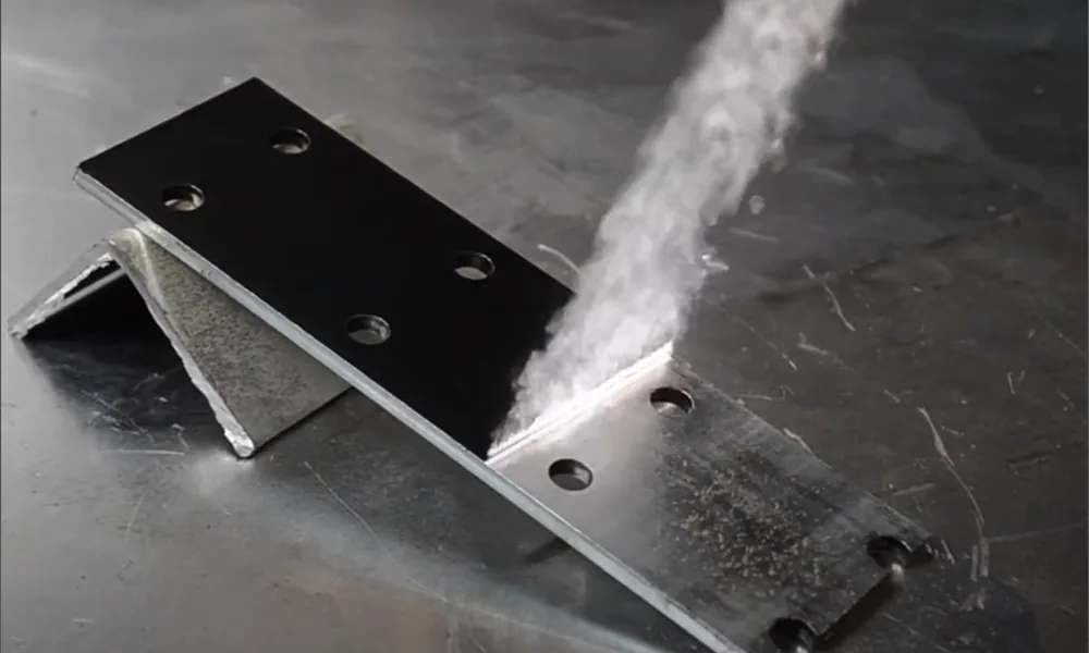
| Mechanism | Typical visual target | Main risk | Evidence needed |
|---|---|---|---|
| Color / reflectance change | Contrast with the oxide still present | Unstable hue, gloss shift, halo or hidden heat damage | Lighting-controlled appearance, repeatability and durability checks |
| Partial oxide removal | Contrast from a controlled window | Uneven thickness, residue, edge drift or protection loss | Removal uniformity, edge inspection and surface review |
| Full removal to substrate | Base-alloy contrast, code or tactile boundary | Substrate discoloration, roughness, corrosion or contamination | Stopping-layer confirmation, cleaning and post-mark protection evidence |
Defined oxide response
Appearance or removal area meets the drawing, stopping layer and inspection method.
Readable but unqualified
Color drift, residue, halo, roughness or uncertain layer condition needs more testing.
Protection compromised
Uncontrolled exposure, delamination, corrosion risk or unstable contrast blocks approval.
06 – Part geometry
How Do Part Shape, Thickness and Size Change the Process?
The oxide is only one part of the process window. Geometry changes focus, spot size, heat sinking, fixture repeatability and whether the full mark can stay inside the approved surface condition.
Flat, rigid parts
These are usually the simplest to fixture and focus. The main variables are surface consistency, field position and whether the oxide response stays uniform across the marked area.
Cylindrical or curved surfaces
Focus and effective spot size change as the surface leaves the focal plane. Long circumferential marks may require rotary motion or another controlled focus strategy.
Thin or low-thermal-mass parts
Thickness affects heat sinking more than the optical interaction with the oxide itself. Thin sections can accumulate heat faster, increasing halo, discoloration or distortion risk.
Large, recessed or multi-height parts
A larger marking field does not automatically solve access or focus. Check field size, smallest feature, fixture datum, depth change, shadowing and whether Z/3D focus or vision is justified.
07 – First-test laser route
Which Laser Route Should Be Tested First?
There is no universal oxide recipe, but the screening order can still be practical. Start with the route most likely to produce the required interaction on the real oxide/base-alloy stack, then move to another wavelength or pulse regime only when the first route cannot meet contrast, heat, feature or layer-integrity requirements.
Start with 1064 nm fiber for many metal/oxide systems
For oxide-bearing metal parts that respond usefully at 1064 nm, Q-switched or MOPA fiber is often the most practical first screening direction for contrast, selective modification or controlled removal.
Bring MOPA fiber forward when pulse control matters
MOPA is still a fiber route. Its wider pulse-width and repetition-rate control can be useful when the trial needs to separate color/reflectance change from removal or reduce an overly narrow thermal window.
Escalate to UV, green or another route for a specific reason
Compare another wavelength when 1064 nm cannot meet feature size, heat, absorption, plume or layer-integrity requirements. CO2 or other routes should remain surface-specific rather than default metal choices.
| Direction | Why it may be screened | Boundary to watch | Sample evidence |
|---|---|---|---|
| Q-switched fiber 1064 nm | Practical first direction for selected metal and oxide surfaces where robust contrast or removal is needed. | Heat can widen the mark, discolor the alloy or change the oxide beyond target. | Artwork across oxide states, edge quality, residue, substrate condition and repeatability. |
| MOPA fiber 1064 nm | Pulse-width and repetition-rate control may compare color change against removal and heat. | MOPA is not automatically gentler or more durable; overlap, focus and energy density still govern. | Side-by-side color/removal matrix, process window and durability after cleaning. |
| UV or green | Screen only when the defined oxide/coating shows useful absorption or a feature/heat benefit; wavelength, throughput, debris and exposed-metal response remain sample-dependent. | Shorter wavelength does not remove the need for focus, extraction, shielding or validation. | Feature fidelity, layer integrity, plume, edge and repeatability. |
| CO2 or other route | Use only when a non-metallic oxide/residue or special finish shows a useful response at that wavelength and the exposed metal path is understood. | Strong interaction can increase heat, roughness, fumes or unintended exposure; metal can reflect or redirect energy. | Removal uniformity, surface condition, extraction, beam controls and post-mark appearance. |
08 – Risks and failure modes
A Readable Mark Can Still Damage the Protective Function
Inspect the mark after the cleaning and handling steps the finished surface will see. A result can look excellent immediately and still fail because the oxide was thinned, loosened or removed outside the allowed area.
Color drift
Hue or contrast changes with lighting, viewing angle, lot, hydration or heat history. Use a defined reference and repeat across surfaces.
Unstable edge
Halo, feathering, residue or undercut can indicate layer variation, focus drift, overlap or redeposition.
Loss of corrosion or protective function
Thinning or removing a protective oxide can expose the substrate, change sealing behavior or alter downstream adhesion. Confirm the stopping layer and whether post-mark protection is required.
Surface contamination
Oxide particles, salts, oil or plume residue can mask the true result. Define cleaning and housekeeping before release.
| Symptom | Check next | Decision |
|---|---|---|
| Color shifts between lots | Oxide origin, thickness, hydration, alloy, lighting and cleaning | Split the qualification group or widen the matrix. |
| Readable but weak after cleaning | Layer retention, residue, cleaning chemistry and sealing | Do not release until post-cleaning is the acceptance state. |
| Edge wider or darker than target | Focus, spot, overlap, pulse behavior, heat and field position | Change the interaction or reject the edge; do not only increase power. |
| Exposed alloy changes appearance | Stopping layer, substrate heat, roughness, reflectivity and protection need | Confirm exposure is allowed and whether post-mark protection is required. |
09 – Real-sample validation
How Should Real Samples Be Validated?
The right sample is the actual oxide state, base alloy, geometry and mark requirement, inspected after the cleaning and durability checks that govern acceptance.
1. Surface record
Oxide origin, base alloy, finish, condition range, cleaning, sealing, storage and permitted exposure.
2. Mark acceptance
Artwork, smallest feature, color reference, removal boundary, edge limit, residue and reading method.
3. Durability record
Wear, solvent, humidity, thermal, corrosion or adhesion checks selected for the actual use.
Define change versus removal
State whether the oxide should remain, change appearance, or be removed to a named stopping layer.
Group real surface states
Test representative alloys, oxide conditions, lots, positions and geometry instead of one clean coupon.
Compare a process window
Hold lighting, cleaning and inspection constant while comparing source direction, focus, overlap and heat.
Translate to production
Add fixture repeatability, extraction, verification, data handling and full cycle time before sizing the machine.
| Dimension | Record | Pass condition |
|---|---|---|
| Appearance | Contrast/color, lighting, gloss and viewing angle | Within the agreed reference and repeatable across samples. |
| Layer boundary | Color change, removal completeness, edge and exposed alloy | Defined stopping layer and edge remain within the drawing limit. |
| Durability | Selected wear, chemical, thermal, humidity or corrosion check | Post-test appearance and layer condition remain acceptable. |
| Process | Cleaning, plume capture, fixture repeatability and cycle inputs | Approved result survives the real downstream workflow. |
10 – Machine configuration
How Is the Final Machine Configuration Chosen?
Once material feasibility is credible, Zhuorui Laser can review the source, optics, fixture and control scope against the sample evidence. The final configuration remains conditional on the finished surface, geometry, cycle and safety review.
Source and optics
Match wavelength, pulse behavior, spot, field and focus to the smallest feature, oxide boundary and heat limit. Machine wattage is not a complete process recommendation.
Fixture and access
Hold flat, cylindrical or irregular surfaces without changing focus or scratching the layer. Rotary, height or vision functions may be evaluated when needed.
Extraction and protection
Review plume, particles, local capture, filtration, optics cleanliness and residue handling. Exposed or polished metal can create direct/specular reflection risk.
Data and verification
Variable data, code verification, line signals and reject handling belong to the configured application. Use the vision positioning solution when required.
| Production condition | Likely direction | Decision boundary |
|---|---|---|
| Fixed flat or low-curvature parts | Standard enclosed 2D marking system may be sufficient after sample approval. | Stable oxide state, fixed artwork, repeatable loading and no unresolved reflection or plume risk. |
| Cylindrical or multi-height geometry | Evaluate rotary, height control or 3D focus options. | Mark access and focus must remain within the approved process window across the full surface. |
| Mixed parts or variable placement | Evaluate vision positioning and a controlled fixture. | Recognition, datum control and verification must be demonstrated on representative parts. |
| Line, serialised or reject-controlled work | Evaluate data integration, verification and automation. | Cycle time, PLC/MES signals, reject handling and safeguarding must be reviewed together. |
11 – Frequently asked questions
Oxide-layer laser marking questions
Can a laser create a durable color change in an oxide layer?
It can be evaluated when the oxide origin, base alloy, target color and use-condition durability are defined. A visible hue is not a durability result.
Does oxide-layer marking always remove the oxide?
No. The target can be a color change with the layer retained, partial removal or full removal to the base alloy. Each mechanism needs a different boundary.
Is anodized aluminum the same as every oxide layer?
No. Anodic layers have their own formation, porosity, color and sealing variables. Qualify them separately from natural or heat-grown oxide.
Which laser is best for oxide-layer marking?
There is no universal answer. Fiber/Q-switched, MOPA, UV, green or another route may be screened according to the layer, target effect, feature size, heat limit and geometry.
Can black-oxide steel be marked without exposing bare metal?
Sometimes a useful contrast change can be screened while keeping the black-oxide layer functionally present, but that cannot be assumed from appearance alone. If the process removes or thins the oxide, confirm the exposed area, corrosion or protection requirement, cleaning condition and durability on the real part.
What should I send for an oxide-layer sample review?
Send finished samples with base alloy, oxide origin/condition, cleaning and sealing history, artwork or drawing, smallest feature/mark size, target mechanism, allowed exposure, inspection method, durability requirement, production cycle time, intended market/standard and automation needs.