Zhuorui Laser / Resources / Technology Guides / CO₂ Laser Marking Technology
Laser Technology Guide
CO₂ Laser Marking Technology
CO₂ laser marking uses long-wave infrared laser energy to create a permanent change at or near the surface of a material without physical contact. Industrial CO₂ systems most commonly operate around 10.6 μm, although 9.3 μm and 10.2 μm sources are also used when their absorption characteristics better match a particular substrate.
The important engineering question is therefore not simply whether a machine uses a CO₂ laser. The useful question is whether the selected wavelength couples effectively with the actual material, what physical change that interaction creates, and whether the resulting mark can meet the application requirement without unacceptable damage.
This is why CO₂ technology is widely associated with wood, paper, cardboard, leather, textiles, acrylic, rubber, glass, coatings, packaging materials, and selected plastics. Depending on the substrate, the visible mark may result from carbonization, localized material removal, melting or foaming, coating removal, or controlled surface modification. The material response—not the laser name alone—determines the result.
What Is CO₂ Laser Marking and How Does It Work?
A CO₂ laser is a gas laser that produces invisible infrared radiation. In a typical galvo marking machine, the laser source generates the beam, galvanometer mirrors steer it across the programmed marking path, and the focusing optics bring the beam to the required spot on the workpiece. The galvanometer performs the scanning function; the focusing lens concentrates the beam over the usable marking field.
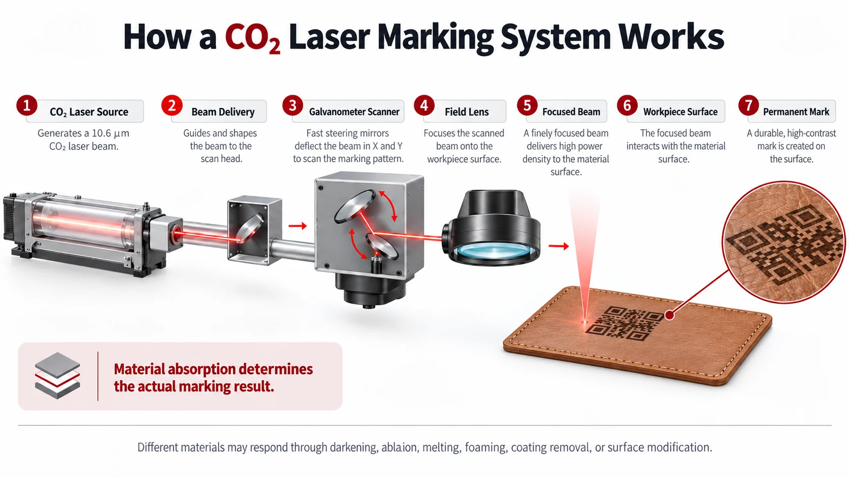
When the beam reaches the workpiece, its energy does not automatically become a mark. Some energy can be reflected, some can pass through the material, and some can be absorbed. The absorbed portion is what can drive the physical change. For many CO₂ applications, that absorbed energy produces localized heating, but the result depends strongly on the substrate.
Wood and paper may darken through localized thermal decomposition. A polymer may melt, foam, discolor, or lose a thin surface layer. A coating may be removed to expose a contrasting material underneath. Glass can develop a white or frosted appearance through controlled surface modification and microfracturing.
This distinction is important because CO₂ laser marking is a laser-source technology, not one universal marking mechanism. The same laser family can create very different marks on different materials.
CO₂ systems are also widely used for engraving and cutting, but those processes have different objectives. This guide focuses on marking, coding, surface modification, and relatively shallow material removal rather than through-cutting. For a broader explanation of the complete interaction chain, see how laser marking works.
Why Is CO₂ Laser Marking Well Suited to Many Non-Metal Materials?
The main reason is the relationship between laser wavelength and material absorption. High laser power alone does not make a process suitable. The material must absorb enough of the selected wavelength, and that absorbed energy must create a useful surface response rather than excessive damage.
The most common general-purpose CO₂ wavelength is approximately 10.6 μm. Many organic and non-metallic materials absorb long-wave infrared energy strongly enough at or around this wavelength to support practical marking, engraving, or surface modification. This is one reason CO₂ systems are commonly applied to wood, paper, cardboard, leather, rubber, acrylic, glass, packaging substrates, and selected polymers.
However, the category name of a material does not fully define its optical response. “Plastic,” for example, may refer to polymers with very different resin chemistry, fillers, pigments, flame retardants, coatings, and layer structures. Two visually similar plastic parts can therefore react differently to the same CO₂ source.
This is also why industrial CO₂ technology is not limited to 10.6 μm. 9.3 μm and 10.2 μm sources are used in selected applications because changing wavelength can change how strongly a specific resin, film, coating, or transparent material absorbs the laser energy. Technical application information from KEYENCE and Novanta documents wavelength-dependent behavior on materials including transparent resins, PET, polypropylene, polycarbonate, and packaging films.
Those results should not be interpreted as a universal ranking in which one CO₂ wavelength is always better than another. The correct conclusion is narrower: the most suitable CO₂ wavelength depends on the absorption behavior of the actual material and the surface effect the application requires.
For many ordinary wood, paper, leather, rubber, acrylic, and general non-metal applications, 10.6 μm remains the natural starting point. Alternate wavelengths become more important when a specific polymer, film, multilayer package, coating, or transparent substrate does not respond acceptably to the default wavelength.
What Are the Main Advantages of CO₂ Laser Marking?
The strongest advantage of CO₂ technology is its usefulness across a broad group of organic and non-metallic materials. A manufacturer working with cartons, wood products, leather goods, acrylic components, rubber, glass, films, or other suitable substrates can address many marking and coding tasks within the same laser-source family.
The process is also non-contact. The laser does not require a cutting tool or print head to press against the workpiece, so the marking operation does not introduce mechanical marking force. This can be useful when the surface could be scratched, distorted, contaminated, or difficult to process using contact methods.
Where the mark is formed directly by modifying or removing material, it can become a permanent part of the surface rather than a separate ink layer. This makes CO₂ marking useful for product identification, date and lot codes, serial numbers, barcodes, 2D codes, logos, graphics, and other variable information on suitable substrates.
Direct laser marking can also reduce dependence on inks, ribbons, labels, or printing plates at the marking stage. That benefit should not be overstated: a complete system can still require extraction filters, cleaning, maintenance components, compressed air, or other production resources. The narrower advantage is that the mark itself can often be created without depositing conventional printing consumables onto the workpiece.
CO₂ technology is also compatible with both stationary workstations and automated production. The same laser family can be configured for manually loaded parts, sheets, cartons, bottles, films, or moving products, although the final machine architecture will depend on the handling and production requirement.
These advantages are strongest when three conditions align: the material absorbs the wavelength effectively, the resulting surface change is acceptable, and the production system can reproduce that change consistently.
What Materials Can CO₂ Lasers Mark?
A compatibility list is useful only when it helps the reader make a decision. The more useful question is how a material typically responds to CO₂ energy, what kind of mark that response may create, and what limitation should be checked before the process is accepted.
| Material Family | Typical CO₂ Interaction | Common Result | Main Point to Validate |
|---|---|---|---|
| Wood | Localized heating and carbonization | Dark marking or shallow engraving | Grain, resin, moisture and excessive charring |
| Paper / Cardboard | Thermal darkening or localized removal | Codes, text and graphics | Burn-through, discoloration and coating variation |
| Leather | Carbonization or surface removal | Contrast, logos and decorative engraving | Construction, coating, scorch and odor |
| Textile | Fiber-dependent melting, carbonization or removal | Patterns, labels and contrast marks | Fiber type, backing, melting and fraying |
| Acrylic / PMMA | Absorption and ablation | Frosted or engraved appearance | Heat effects and edge quality |
| Rubber | Thermal modification or ablation | Contrast or shallow removal | Formulation, smoke and residue |
| Selected Plastics | Melting, foaming, color change or ablation | Coding, contrast or surface modification | Resin, additives, pigments and wavelength |
| Films | Wavelength- and layer-dependent interaction | Coding or selective surface change | Film thickness, multilayer structure and heat damage |
| Glass | Localized thermal stress and surface microfracturing | White or frosted mark | Cracking and acceptable surface damage |
| Coatings / Inks | Selective upper-layer removal or modification | Exposed contrasting layer | Selectivity and damage to the base material |
| Packaging Substrates | Material-specific surface response | Dates, lots, barcodes, 2D codes and graphics | Readability, package integrity and production consistency |
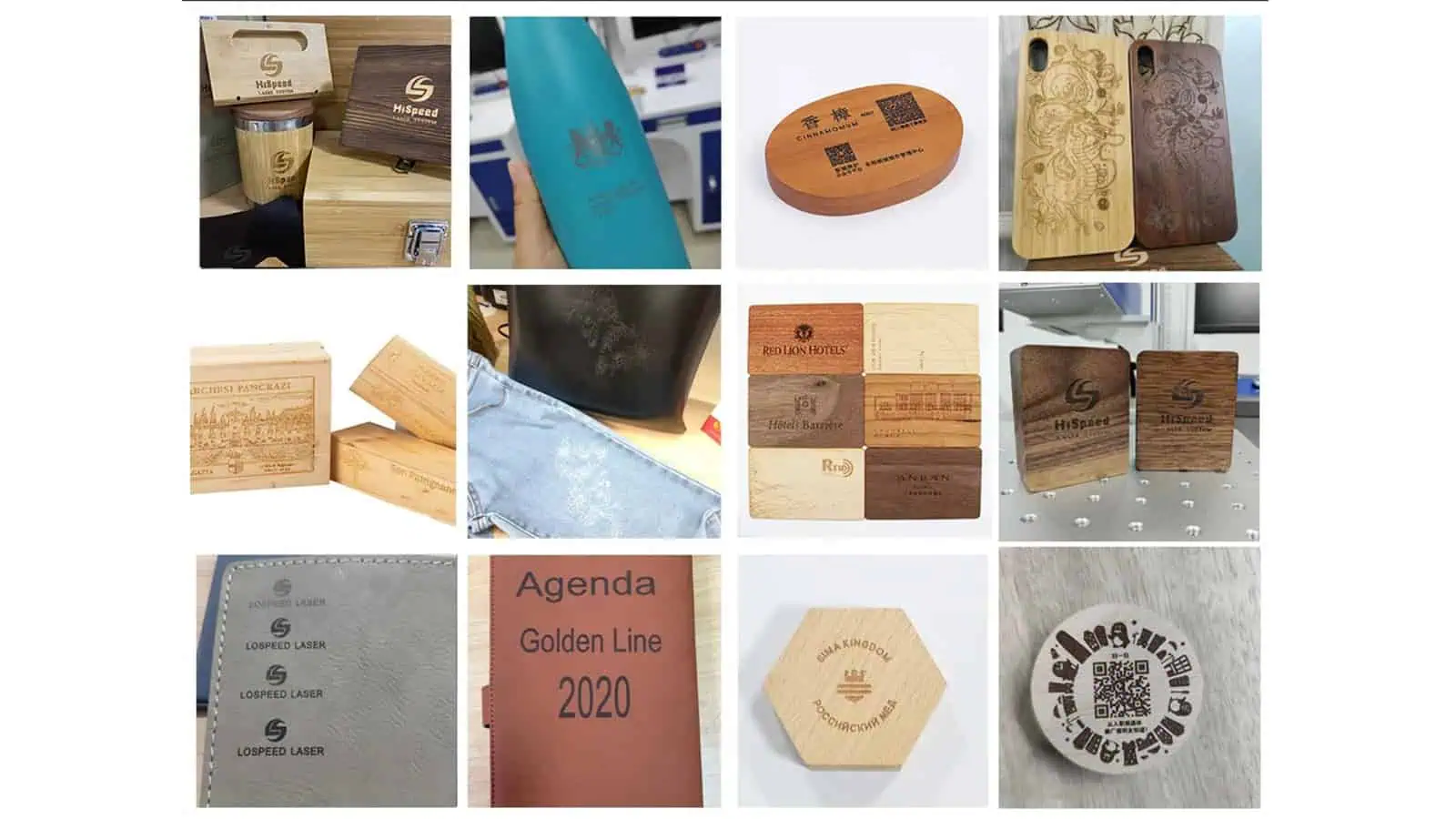
The table should be treated as an orientation map rather than a universal compatibility guarantee. For material-specific guidance on wood, leather, paper, cardboard, and textiles, continue to the organic materials marking guide.
Wood, paper, and cardboard are among the most intuitive CO₂ applications because localized heating can readily produce visible contrast or controlled removal. Their apparent simplicity can be misleading, however. Wood species, grain, resin content, moisture, paper coating, recycled content, and board construction can all change how the surface responds. One attractive sample therefore does not establish a process window for every batch or supplier.
Acrylic is another well-established CO₂ material because it can absorb long-wave infrared energy strongly enough to produce a characteristic frosted or engraved appearance. Even here, “acrylic” is not a complete engineering specification. Grade, thickness, pigment, additives, and manufacturing route can influence the result.
Rubber introduces a different concern. The material may accept a visible mark relatively easily, while the production problem becomes smoke, odor, carbonaceous residue, formulation variation, or excessive heat damage. The engineering question is therefore not merely whether the rubber can be marked, but whether the resulting mark and byproducts are acceptable.
Plastics and films require particular caution when making broad compatibility claims. Two products both described as “plastic film” may have different polymer chemistry, fillers, pigments, flame retardants, coatings, or layer structures. Technical work on alternate CO₂ wavelengths demonstrates why this matters: PET, polypropylene, polycarbonate, and other substrates can respond differently when wavelength changes.
Textile response likewise depends first on fiber composition, but the complete construction matters. Weave, dyes, coatings, backing layers, adhesives, moisture, and production tension can change how heat develops at the surface and therefore affect melting, edge quality, contrast, and repeatability. A clean result on one polyester textile should not be treated as proof that the same process will transfer unchanged to another fabric construction.
Leather should also be treated as a complete material system rather than a single substrate category. Natural and synthetic constructions can respond differently, while pigments, protective finishes, backing layers, and thickness can alter contrast, material removal, scorch behavior, and odor. The actual production leather is therefore more meaningful evidence than a generic claim that a machine is “leather compatible.”
Glass can be marked with CO₂, but its mechanism requires a different acceptance mindset. KEYENCE’s CO₂ marking guidance describes a white or frosted result associated with localized surface microfracturing. That same mechanism explains why a visually good mark does not automatically prove that the surface condition is acceptable for a strength-sensitive glass component.
What Types of Marks Can a CO₂ Laser Produce?
Understanding the physical marking mechanism is more useful than memorizing a list of compatible materials because the visible mark is only the final consequence of how the substrate responded to absorbed energy.

Carbonization and Thermal Darkening
Wood, paper, cardboard, leather, and some other organic materials can darken when absorbed laser energy raises the local temperature enough to change the surface. The useful outcome is controlled contrast. The failure mode develops from the same thermal process: useful darkening can progress into excessive charring, edge spread, discoloration outside the mark, or material damage. More energy therefore does not automatically produce a better result.
Ablation and Material Removal
When enough energy is absorbed to remove a thin layer of material, the result becomes an etched or engraved feature rather than only a color change. The same principle can be used to remove paints, inks, or coatings and expose a contrasting layer underneath. In these applications, selectivity becomes critical: the process must remove enough of the intended layer without causing unacceptable damage to the substrate below.
Polymer Foaming, Melting and Surface Modification
Some polymers develop contrast through localized melting, foaming, restructuring, or color change rather than simple carbonization. This is another reason why the statement “CO₂ can mark plastic” is too broad. Two polymers may both accept a visible mark while reaching that result through different physical changes and therefore having different quality limits.
Frosted Marking on Glass
Glass behaves differently again. Localized thermal stress can create very small surface fractures that scatter light and appear white or frosted. This can produce a permanent visible mark, but the desired visual mechanism and the damage mechanism are closely related. Excessive interaction can push the surface beyond acceptable cosmetic or mechanical limits.
Across these mechanisms, the useful principle is the same: the mark is created by the material response, not by the laser source alone. A photograph labeled only as a “CO₂ laser sample” therefore provides limited engineering evidence unless the substrate and resulting surface mechanism are also understood.
Where Is CO₂ Laser Marking Commonly Used?
Packaging and variable-data coding are among the most established industrial uses of CO₂ technology. Cartons, labels, bottles, films, foils, coated packaging, and other substrates may carry manufacturing dates, expiration dates, lot numbers, traceability codes, barcodes, 2D codes, or branding created directly by the laser. For application-specific examples, see packaging and coding applications.
Packaging also shows why a general “CO₂ compatible” label is not enough. Paperboard, PET, polypropylene film, coated cartons, and glass containers are very different material systems. Wavelength-specific application studies show that changing CO₂ wavelength can materially change the response of particular PET or polypropylene applications, so the real packaging substrate remains part of the technology decision.
Wood products commonly use CO₂ marking for branding, identification, graphics, decorative patterns, and shallow engraving. Natural variation matters here: grain, resin, surface finish, and moisture can cause visible differences even when the equipment itself is stable.
Leather and textile applications include logos, labels, decorative patterns, surface effects, and identification. These are valid CO₂ applications, but their success depends heavily on the actual construction rather than simply the words “fabric” or “leather.” Fiber type, finish, backing, coatings, tension, scorch, fraying, and handling remain important application variables without defining CO₂ technology as a whole.
Acrylic, rubber, and selected plastics can support branding, codes, graphics, and surface modification when their absorption behavior is suitable. Glass bottles, containers, and flat-glass products form another common application group where a permanent frosted mark is acceptable.
The unifying factor across these industries is not the product category. It is the presence of a surface that absorbs CO₂ energy strongly enough to create a controlled, useful, and repeatable change.
What Are the Main Limitations of CO₂ Laser Marking?
CO₂ performs well on many non-metallic materials, but that does not make it the default laser for every non-metal application.
The clearest boundary is direct bare-metal marking. For common industrial metals such as stainless steel, carbon steel, aluminum, and titanium, Fiber laser technology is generally the more natural starting route. A painted, coated, anodized, or laser-reactive metallic surface can behave differently because the laser may be interacting mainly with the upper layer rather than directly with the bare metal. Bare-metal interaction and coating interaction should therefore not be treated as the same application.
Heat sensitivity creates another boundary. CO₂ marking commonly relies on thermal interaction. If the acceptance requirement permits almost no melting, deformation, discoloration, swelling, or surrounding heat effect, a UV source may deserve evaluation even when the substrate could technically produce a CO₂ mark.
Material variability can narrow the process window as well. This is especially relevant to polymers, textiles, leather, coatings, natural materials, and multilayer packaging. A process qualified on one formulation may not transfer reliably to another, even when both products carry the same broad commercial description.
Glass is a further example of a material that can be marked but still requires a clear acceptance boundary. A frosted mark may be visually correct while introducing more microfracturing or surface damage than the particular product can tolerate.
The final limitation is commercial rather than purely physical: markable does not necessarily mean manufacturable. A visible sample can still fail if its readability varies, marking takes too long, material batches change the contrast, excessive residue develops, extraction becomes impractical, or the result cannot be reproduced under the intended production conditions.
A useful feasibility decision therefore has to go beyond whether the laser can make a visible mark.
What Risks and Precautions Should Be Considered with CO₂ Laser Marking?
Technical suitability and safe processing are different questions. A substrate may accept a high-quality CO₂ mark while the process still creates unacceptable emissions, fire risk, contamination, laser-access risk, or product damage.
Material Identification and Process Emissions
Unknown plastics, synthetic leather, films, coatings, adhesives, foams, and multilayer products should not be identified from appearance alone. Thermal decomposition products depend on the real material chemistry.
NIOSH research on CO₂ laser processing of fabrics and polymers detected material-dependent particulate and volatile emissions and found that local exhaust ventilation was important for contaminant control in the evaluated system. That research involved laser cutting rather than ordinary low-removal marking, so its measured concentrations should not be transferred directly to every marking process. The useful conclusion is narrower: laser-generated emissions depend on both material and process intensity, so the safety of an unknown polymer should not be guessed.
Extraction should therefore be considered part of process design. In addition to controlling airborne contaminants, effective extraction can remove smoke and odor, reduce residue on the workpiece, and help limit contamination of optics and surrounding equipment. The required extraction capacity still depends on what is being processed and how aggressively material is being modified. For deeper implementation guidance, see the fume extraction guide.
Heat, Combustible Materials and Fire Risk
Wood, paper, cardboard, textiles, foams, leather, and some polymers can char or ignite if localized heating becomes excessive. This is not merely a cosmetic defect. It affects enclosure design, supervision, residue management, extraction, emergency stopping, and the way the complete machine is operated.
Material that marks successfully under one condition can also become less stable when processing density, dwell time, contamination, or residue accumulation changes. Production validation should therefore consider whether the process remains controlled under foreseeable operating variation, not just whether one sample looks acceptable.
Laser Radiation and Machine-Level Protection
Industrial laser sources can present high optical hazards, but the source classification and the accessible hazard of a complete machine are not automatically the same. A high-hazard source can be incorporated into an enclosed, interlocked machine that prevents hazardous beam access during normal operation.
OSHA laser-safety guidance describes enclosure and interlock controls as part of the engineering-control approach for embedded higher-hazard laser sources. The relevant safety judgment therefore belongs at the complete-system level and should consider the enclosure, access openings, interlocks, beam path, service access, emergency controls, operating procedures, and applicable local requirements.
Product Damage Is Also a Risk
Risk review should include the workpiece as well as the operator. A visually acceptable mark can still be rejected because it weakened glass, melted a textile edge, scorched paper outside the code, distorted a thin film, penetrated a coating too deeply, or generated excessive residue. These failure conditions should be defined before testing so that a good-looking sample is not mistaken for a qualified process.
CO₂ vs Fiber vs UV Laser Marking: What Is the Difference?
CO₂, Fiber, and UV should not be understood as three power levels of the same marking tool. Their different wavelengths change how materials absorb the laser energy, which is why their most natural application areas differ.
| Laser Family | Typical Starting Point | Why It Is Commonly Considered |
|---|---|---|
| CO₂ | Wood, paper, leather, textile, acrylic, rubber, glass, packaging and selected plastics | Useful absorption and thermal interaction across many organic and non-metal surfaces |
| Fiber | Stainless steel, steel, aluminum, titanium and many other industrial metals | Common first route for direct industrial metal marking |
| UV | Selected plastics, sensitive substrates, fine features and applications with strict thermal limits | Short wavelength can provide strong absorption with reduced unwanted thermal influence in suitable materials |
This is a first-pass selection map rather than a universal compatibility chart.
Plastic illustrates why a simple classification fails. Depending on the resin formulation and required result, CO₂, Fiber, or UV may all be credible candidates. Glass also crosses technology boundaries because different applications may prioritize frosting, fine surface modification, contrast, or lower surface damage. Coated metals provide another example: the laser may be interacting mainly with the coating rather than the metal underneath.
The first decision is therefore which laser family provides the most credible starting point. The second and more important decision is whether that source produces the required result on the actual substrate without violating the application’s quality or safety limits.
For a deeper technology comparison, continue to Fiber vs CO₂ laser marking or UV vs CO₂ laser marking. For the purpose of this page, the important principle is that wavelength, material response, and required mark should be evaluated together.
How Do You Know If CO₂ Is Right for Your Application?
A useful selection process begins with the workpiece rather than the laser specification sheet.
First, identify the material as precisely as the project allows. “Plastic,” “fabric,” “leather,” or “coating” may be adequate for an initial discussion, but they are rarely enough for a final engineering judgment. Resin family, fiber composition, surface finish, pigment, coating, backing, adhesive, and layer construction can all change the response.
Next, define the physical result the application actually needs. A dark logo, a white frosted code, shallow engraving, coating removal, a decorative pattern, and a high-readability DataMatrix are different process objectives. A substrate may support several of them, but not necessarily through the same laser family or marking mechanism.
The reject criteria are equally important. A project that permits moderate darkening has a very different process window from one that permits no melting, cracking, halo, residue, burn-through, swelling, or visible color change around the code. Without these limits, a technically impressive sample may still fail the real application.
At that point, laser-family selection becomes more meaningful. Organic materials and many non-metal surfaces often make CO₂ a strong starting candidate. Direct bare-metal marking generally moves the initial evaluation toward Fiber. Highly heat-sensitive materials, fine features, or applications where surrounding thermal change must be minimized may justify UV evaluation.
Production conditions then determine how much confidence can be placed in a laboratory sample. A manually loaded flat sheet, a curved bottle, a moving carton, a continuous film, and a tensioned textile web can create different focus, positioning, handling, extraction, and repeatability requirements even when the material itself has already been shown to mark successfully.
Once CO₂ appears technically credible, the next question should therefore not be “which wattage should I buy?” It should be:
Can the real substrate produce the required mark, within the defined reject limits, under conditions representative of production?
That is the point at which general material compatibility becomes an evidence-based application decision.
What Should Be Verified in a CO₂ Laser Sample Test?
A useful sample test should answer a defined production question rather than simply prove that the laser can create a visible mark. The strongest test uses production-representative material, defines the required effect before testing, records what counts as rejection, and evaluates whether the result is relevant to the intended manufacturing condition.
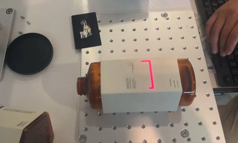
For a meaningful review, the sample package should ideally establish five things:
- The actual material: the relevant grade or formulation, color, coating, finish, thickness, backing, adhesive, or layer construction.
- The real marking requirement: the artwork, code type, mark size, smallest critical feature, desired appearance, contrast, and any readability requirement.
- The reject criteria: unacceptable scorch, melting, cracking, burn-through, residue, swelling, coating damage, color shift, deformation, or loss of mechanical integrity.
- The intended production condition: whether the product is stationary or moving, manually loaded or automated, and whether normal material or batch variation must be represented.
- The acceptance method: how success will actually be judged, such as visual appearance, machine readability, durability, dimensional condition, or another agreed inspection criterion.
The test itself should answer a real decision rather than produce a random collection of settings. If the concern is whether 10.6 μm causes too much swelling on a particular resin, an appropriate wavelength comparison can test that hypothesis. If the concern is whether a glass mark produces unacceptable cracking, inspection must evaluate the damage boundary rather than contrast alone. Manufacturer application data can help define these questions, but settings demonstrated on another material or machine should not be copied as universal recipes.
A successful sample review should ultimately establish three things: the required mark can be produced, it can be produced without unacceptable material or safety consequences, and the evidence is relevant enough to the intended production environment to justify the next stage of machine selection.
That distinction is important. A good-looking sample establishes much less than a validated application. The purpose of testing is to move from “CO₂ appears suitable” to one of three useful conclusions: CO₂ is suitable under the tested conditions, further validation is required, or another laser family should be evaluated.
If CO₂ appears to be the right starting technology, include the actual material, target mark, reject criteria, and intended production condition in your inquiry so the application can be reviewed before machine selection. Request a Quote.