
355 nm UV Laser Marking
UV Laser Marking Machines
Explore desktop, split, enclosed, CCD, flying and 3D UV laser marking machine configurations for plastics, glass, coated surfaces, electronics and other precision marking applications.
Send your part, marking requirement and production method to review the right UV machine route before quotation.
- 355 nm UV marking route for fine-detail applications
- Desktop, split, enclosed, CCD, flying and 3D configurations
- Sample-first machine selection and application review
UV machine families
Compare UV laser marking machine structures and functional configurations
The families below are not all mutually exclusive categories. Some describe the machine body, while others describe a cooling, vision, 3D or production-line configuration. Use them to narrow the equipment architecture before finalizing the source and optics.
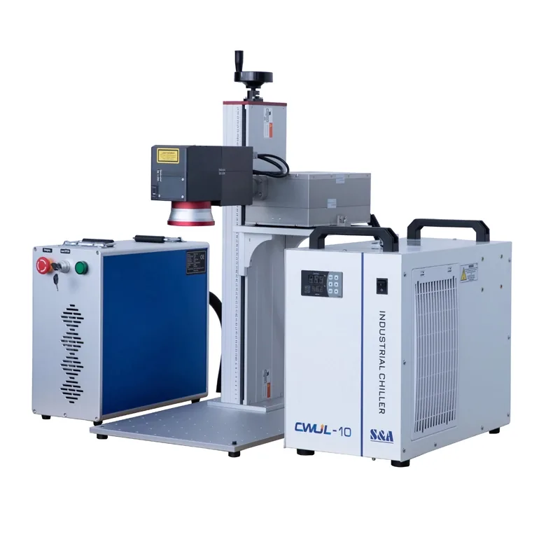
3D optical configuration
3D UV Split Laser Marking Machine
Designed for parts with curved, stepped or variable-height surfaces where a conventional flat-field setup may not keep the complete marking area in focus.
See selection factors >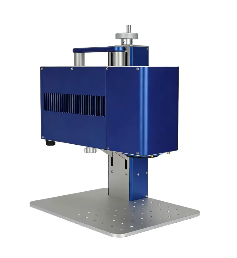
Cooling configuration
Air-Cooled UV Laser Marking Machine
A compact UV route for applications where the selected UV source supports air cooling and the machine needs to fit a smaller workstation or integration space.
Compare selection factors >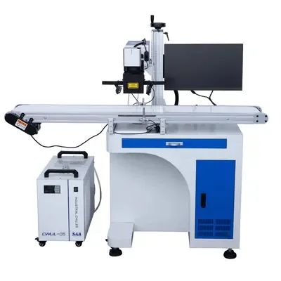
Vision configuration
CCD UV Laser Marking Machine
Uses camera-based positioning when parts do not always arrive in one fixed position or when the marking process needs visual location before marking.
See vision selection factors >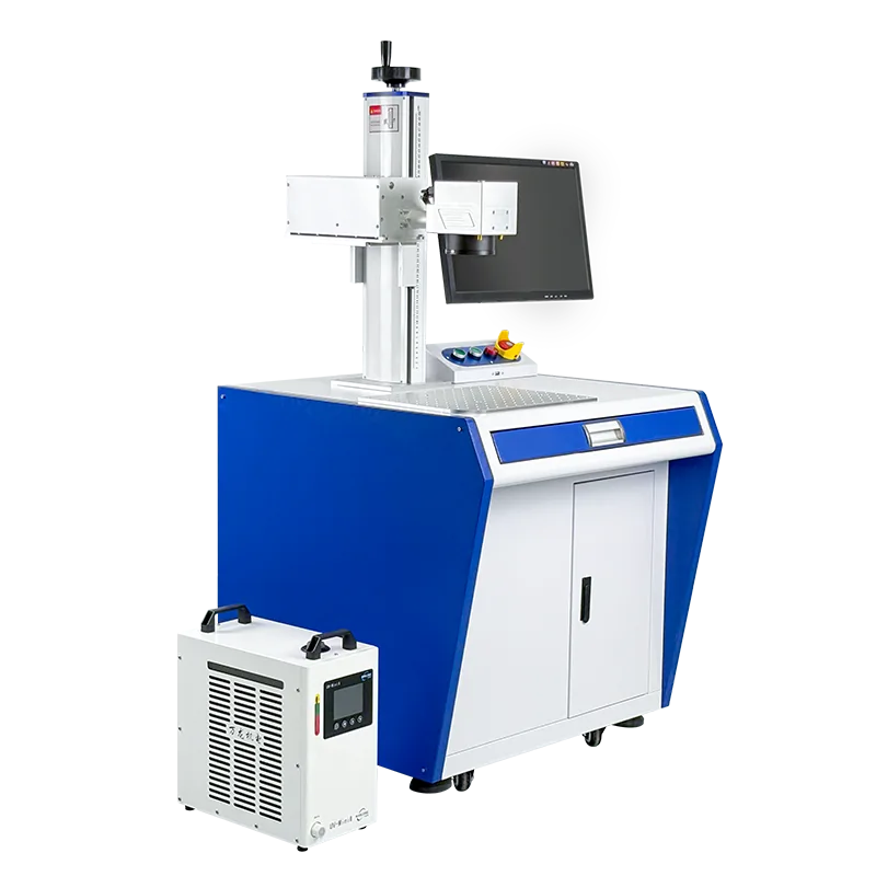
Machine structure
Industrial Desktop UV Laser Marking Machine
A self-contained workstation format for manual loading, fixture-based positioning and repeatable daily production in a dedicated work area.
Compare workstation structures >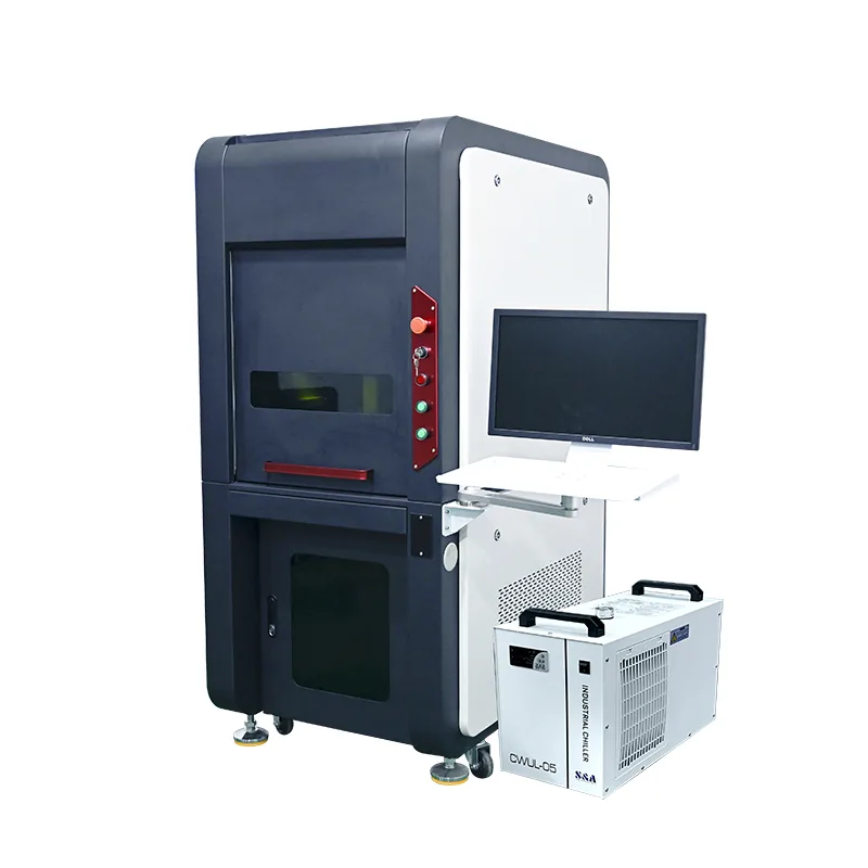
Machine structure
Enclosed UV Laser Marking Machine
Adds a guarded work area around the marking process and is useful where operator access, fume extraction and a defined machine boundary need closer control.
See enclosure considerations >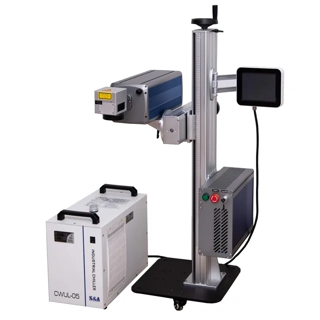
Production integration
Flying UV Laser Marking Machine
For online coding where products move through the marking position and the machine must coordinate trigger, encoder, product spacing and data with the production line.
View flying marking solution >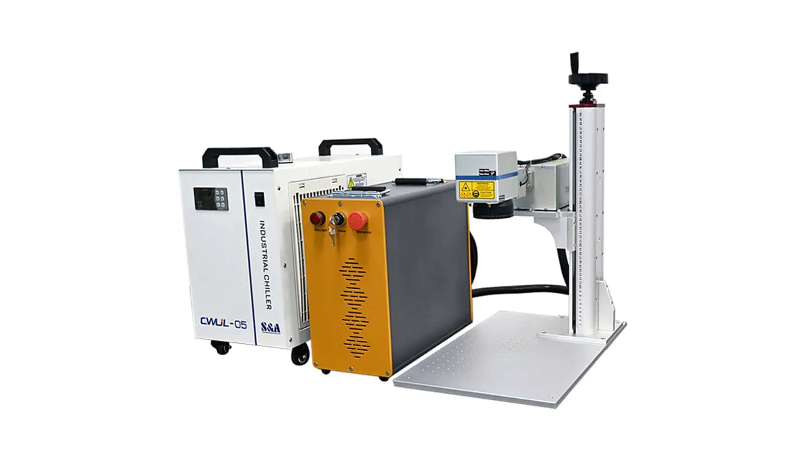
Machine structure
Split UV Laser Marking Machine
Separates the marking head from the main equipment cabinet, making it easier to work around custom fixtures, larger parts or an existing workstation.
Compare split and table structures >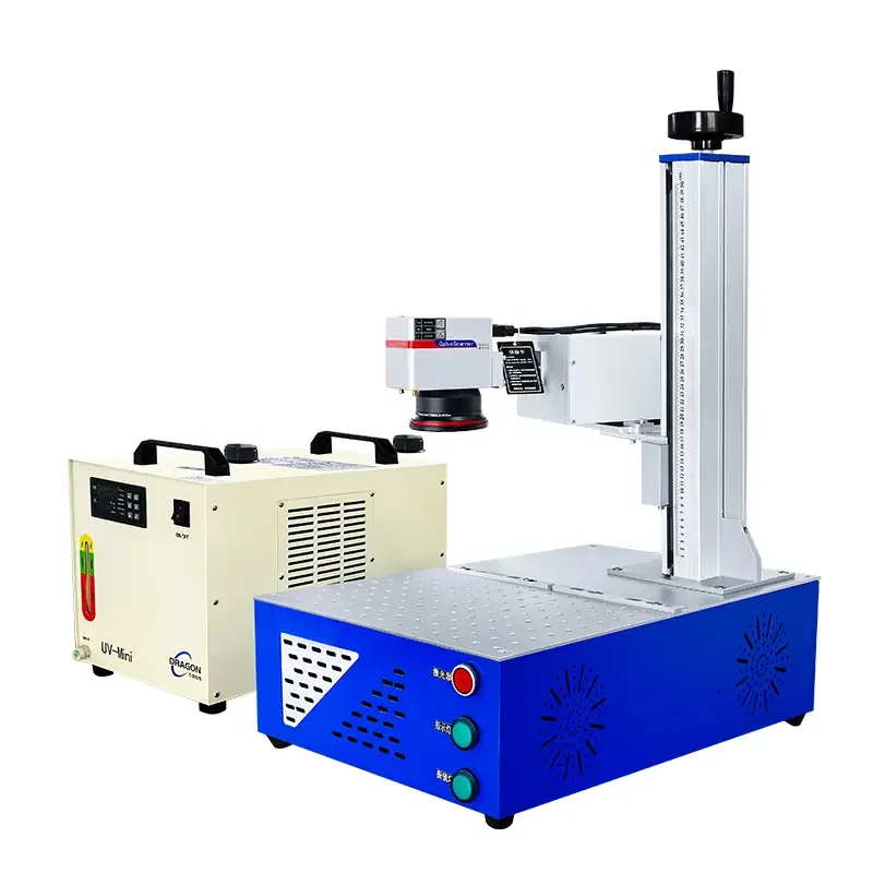
Machine structure
Table UV Laser Marking Machine
Combines the UV marking system and operator work surface into one workstation for fixture-based loading, repeatable setup and general production use.
Compare workstation structures >Structure comparison
Choose the machine structure from loading, positioning and production flow
Machine structure should follow how the part is presented to the laser. A good UV optical result can still become difficult to use in production if the fixture, access, focus adjustment or line interface is wrong.
| Machine route | Use it when | Main advantage | Main engineering checks |
|---|---|---|---|
| Desktop / Table | Operators manually load parts into a defined work area. | Simple workstation layout and repeatable fixture positioning. | Work area, Z travel, fixture height, operator access and guarding. |
| Split | The marking head must fit around a custom fixture, large part or existing equipment. | More flexible equipment placement. | Head support, cable reach, vibration, focus adjustment and safety boundary. |
| Enclosed | A guarded workstation and controlled access are required. | Better separation of the marking zone from the operator area. | Door access, interlock design, extraction and complete-system safety review. |
| CCD Vision | Part position varies or visual location is required before marking. | Reduces reliance on a single fixed part position. | Camera field, datum definition, lighting, calibration and software logic. |
| 3D UV | The marking surface has significant height variation, curvature or steps. | Better focus control across non-flat geometry. | Part geometry, usable 3D field, fixture, optical path and mark distortion. |
| Flying / Online | Products move continuously or index through a production line. | Integrates marking into production flow. | Line speed, trigger, encoder, data source, spacing, verification and reject logic. |
How to choose
Do not choose a UV laser marking machine from wattage alone
A UV machine is a combination of laser source, optics, mechanics, cooling and production handling. The right configuration starts with the finished part and the acceptance criteria.
- Material and surface: polymer formulation, glass type, coating, ink, laminate, adhesive, pigment, finish and surface condition.
- Target mark: contrast, frosted effect, dark mark, coating removal, fine text, logo, QR code, Data Matrix or cosmetic detail.
- Part geometry: flat, curved, recessed, transparent, thin-wall or multi-level surfaces can change the optical and mechanical route.
- Marking field: choose the field from the part and mark size; do not increase field size without considering spot size and detail requirements.
- Production method: manual loading, fixture-based batch work, camera positioning, indexed automation or continuous line marking require different machine structures.
- Acceptance criteria: appearance, readability, durability, cycle time and repeatability should be defined before the final configuration is approved.
Materials and application direction
Where UV laser marking is commonly evaluated
UV is often considered when fine detail and lower thermal loading are important, but the final result still depends on the exact substrate, additives, coatings and target mark. Sample testing is the safest way to confirm suitability.
Plastics & Polymers
Useful to evaluate for fine identification, high-contrast marking and applications where excessive melting or heat distortion should be minimized.
Explore material guidance >Glass & Transparent Parts
Can be evaluated for fine surface marking or frosting effects, with process settings selected to control appearance and reduce unwanted damage.
Explore material guidance >Coated & Printed Surfaces
Useful where the marking task involves a coating, ink or layered surface and the objective is controlled surface modification rather than deep material removal.
Explore application guidance >Electronics & Precision Parts
Often considered for small text, identification codes and fine marks on electronic housings, components and other parts with limited tolerance for thermal impact.
Explore application guidance >Configuration and sample test
Match the UV machine to the sample before finalizing the equipment
Zhuorui’s role is to assemble, configure, debug, test and supply the complete laser marking machine. For UV applications, the most useful selection process is to start from the real part and then confirm the laser, optics and machine structure around the required result.
Review the material and surface
Identify the substrate, coating, color, geometry and the exact area that needs to be marked.
Define the target mark
Confirm the required contrast, detail, code quality, appearance, durability and available cycle time.
Select source, optics and structure
Match the UV source route, optical field, focus adjustment, cooling, fixture and machine structure to the application.
Validate with the real sample
Use the finished or representative part to confirm that the proposed configuration can meet the actual marking requirement before purchase.
FAQ
UV laser marking machine questions
What is a 355 nm UV laser marking machine used for?
355 nm UV laser marking is commonly evaluated for plastics, glass, coated surfaces, electronics and other applications where fine detail and reduced thermal impact are important. The exact result depends on the material formulation, surface condition and process settings.
Is UV laser marking a completely cold process?
No. UV is often described as a low-heat or cold-processing route because its shorter wavelength can reduce heat-affected behavior in many applications, but the process still involves energy transfer. Pulse conditions, speed, focus and the material itself determine the final thermal effect.
How should I choose UV laser power?
Do not choose power in isolation. The right source depends on material response, target mark, optical field, processing speed, duty cycle and the acceptable process window. A sample test is more reliable than selecting a machine from wattage alone.
How do I choose the marking area?
Start from the actual mark size and part geometry. A larger field can cover more area, but it can also change spot size and fine-detail performance. The field lens should therefore be selected together with the required mark quality.
When should I choose CCD vision or 3D UV marking?
Choose CCD vision when part position varies and the system needs camera-based location before marking. Choose a 3D route when the marking surface has meaningful height variation or curvature that cannot be handled well by a conventional flat-field setup.
When is a flying UV laser marking machine appropriate?
Flying UV is appropriate when products move through a production line and marking must synchronize with product position, trigger signals, encoder feedback and production data. Line speed and product spacing must be reviewed as part of the system.
Can Zhuorui test my material before machine selection?
Send the actual or representative part, material information, surface condition, mark file, target appearance, mark size and production requirement. These inputs allow the UV configuration and sample-test route to be evaluated more accurately.
Next step
Send your part and marking requirement for UV machine selection
Include the material, surface condition, mark file, mark size, target result, part geometry, loading method and expected cycle. Zhuorui can then review the suitable UV machine structure and the configuration items that need to be confirmed before quotation.