
PC Material Compatibility
Polycarbonate Laser Marking
Polycarbonate can be laser marked, but the usable process window depends on the actual PC grade, transparency, additives, molded stress, surface condition and the result you need. This guide helps you decide what to test first, what can go wrong, how to validate the real part and how the sample result translates into machine configuration.
Request a Quote OEM & Custom InquiryQuick Answer
Yes, PC Can Be Laser Marked — but the Grade and Stress State Decide the Window
For clear, white, fine-detail or appearance-sensitive PC, UV is commonly a practical first route to evaluate. Fiber or MOPA can be useful on selected opaque, colored or laser-responsive PC grades when the material absorbs effectively at the test wavelength. CO2 may create a frosted or engraved surface effect, but thermal discoloration, melt and haze require careful review.
The decision is not simply whether a laser can make a visible mark. The mark must also meet the required contrast, code readability, surface appearance and durability without unacceptable damage to the final molded part.
Material Inputs
Which Polycarbonate Variables Change Laser Marking Results?
The name “polycarbonate” is not enough for process selection. Two PC parts can respond differently because of formulation, optical state, surface finish and molding history.
Transparency & color
Clear, translucent, natural, white, black and colored PC can differ in absorption and visible contrast. Transparent parts also need controlled lighting and background conditions during inspection.
Additives & formulation
UV stabilizers, flame retardants, pigments, fillers, recycled content and laser-sensitive additives can change absorption, mark color and thermal behavior.
Molded-in stress
Gate areas, weld lines, thin walls, sharp corners, snap features, bosses and bent regions can be more sensitive to whitening, cracking or local deformation.
Surface condition
Hard coatings, printed layers, protective films, texture and gloss can change whether the process interacts with the PC itself or primarily removes or modifies a surface layer.
Part thickness
Thin sections can tolerate less local heat before visible distortion or stress effects appear. Thick sections may be more thermally stable but still need surface and optical review.
Acceptance requirement
A visible logo, a cosmetic mark and a machine-readable Data Matrix do not have the same acceptance threshold. Define the pass/fail criteria before sample approval.
Products & Use Cases
Where Is Polycarbonate Laser Marking Used?
PC is used where impact resistance, transparency, dimensional stability or molded detail matters. Laser marking is typically considered when the part needs durable identification, traceability or product information without adding a separate label.
Marking Content
What Is Usually Marked on Polycarbonate?
The content being marked changes the process requirement. A large logo can tolerate a different edge quality and contrast window from a small code that must be read reliably by a scanner.
Identification
Part numbers, model numbers, serial numbers and product identifiers.
Traceability
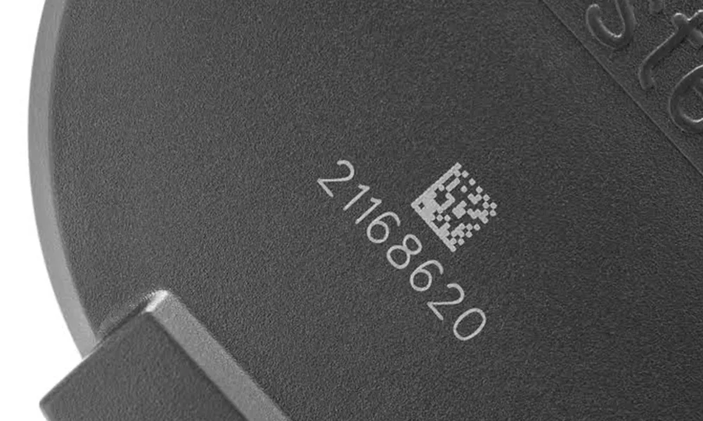
Lot codes, batch codes, date codes, QR codes, Data Matrix and barcodes.
Product information
Symbols, operating identifiers, logos and assembly marks.
Inspection-critical codes
Small machine-readable codes where edge definition, quiet zone and scanner setup matter.
Desired Marking Result
What Result Do You Need on the PC Part?
Choose the acceptance target before the laser route. Contrast, tactile change, optical appearance and code readability create different process windows.
Dark visible mark
Typical for light or natural PC identification.
- Watch for
- Brown halo, excess heat and weak contrast.
- Test focus
- Material response, pulse strategy and heat accumulation.
Light / frosted mark
Useful on dark, colored or transparent PC.
- Watch for
- Haze, viewing-angle dependence and surface texture.
- Test focus
- Inspect under the real lighting and background condition.
Fine low-tactile mark
For cosmetic housings, covers and small text.
- Watch for
- Surface disturbance and soft edge definition.
- Test focus
- Prioritize a controlled fine-marking window over visible depth.
QR / Data Matrix
For traceability and identification.
- Watch for
- Cell definition, contrast and scanner inconsistency.
- Test focus
- Validate with the intended scanner and inspection setup.
Shallow engraving
For non-optical surfaces where tactile change is acceptable.
- Watch for
- Melt, roughness, discoloration and edge quality.
- Test focus
- Confirm that added depth is actually required.
Subsurface / internal effect
A specialized route for selected transparent applications.
- Watch for
- Optical-path suitability and unintended internal damage.
- Test focus
- Do not assume standard surface-marking capability applies.
Part Geometry
How Do Shape, Wall Thickness and Part Size Change PC Laser Marking?
A process that looks stable on a flat coupon may behave differently on the final molded part. Geometry changes local stress, heat tolerance, focus and positioning requirements.
Thin walls & edges
Thin sections, edges and narrow ribs can be more sensitive to local heat, deformation and stress whitening. These areas should be included in the real-part sample test.
Gates, bosses, snaps & stressed zones
Molded-in stress can make some areas more vulnerable to microcracking. For transparent molded PC, polarized-light stress inspection can be useful when residual stress is a concern.
Curved or height-varying surfaces
Curvature and height variation change focus and spot size across the mark. Stable production may require a fixture, controlled part orientation, focus compensation or evaluation of a 3D marking approach.
Large parts & restricted mark areas
Part size affects machine access, working distance, marking field and lens choice. Large PC parts may also need dedicated positioning or fixturing even when the mark itself is small.
Transparent PC
Clear Polycarbonate Needs Defined Viewing Conditions
A mark on transparent PC can look different with background color, transmitted light, reflection and viewing angle. For lenses, covers and windows, the inspection method is part of the process.
Control the background
Check the mark against the light and dark backgrounds used in real inspection. A frosted mark may look strong in one condition and weak in another.
Protect optical areas
Review haze, scatter, distortion and surface texture around the mark. Effects tolerated on a housing may be unacceptable on an optical or viewing zone.
Verify code reading
For QR or Data Matrix marks, define scanner type, lighting, angle and whether the code is read directly or through the transparent part.
First-Test Laser Route
Which Laser Should You Test First on Polycarbonate?
Do not choose by wattage alone. Start with the PC formulation, optical state, target effect and acceptable thermal damage, then compare only the routes that make sense for that part.
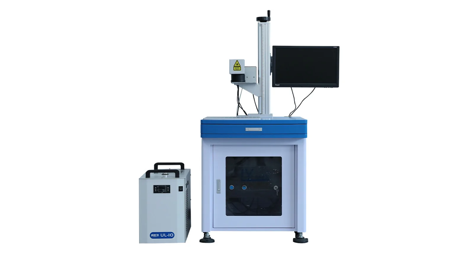
UV laser marking is commonly a practical first route to evaluate. Confirm contrast, haze and stress response on the real part.
Compare UV with fiber or MOPA fiber when the material shows useful absorption and contrast. Do not assume every unmodified PC grade will respond well at 1064 nm.
Green laser can be a secondary comparison route when the UV or 1064 nm result does not meet the target. Suitability is sample-dependent.
CO2 marking or engraving can be evaluated where tactile or surface change is acceptable, with particular attention to yellowing, browning, melt and haze.
Use a small comparative sample matrix rather than locking a machine route from the polymer name alone.
Risks & Failure Modes
What Commonly Causes a PC Mark to Fail?
A readable mark can still be unacceptable if the surrounding PC changes color, becomes hazy, melts or cracks. Failure review should include the material, the mark zone and the final inspection condition.
| Risk | Typical symptom | What to check | Process response |
|---|---|---|---|
| Yellowing or browning | Warm-colored halo or degraded-looking edge around the mark | PC grade, heat input, pass count, focus and thermal route | Reduce accumulated heat, compare a different pulse or source route, and retest on the final sample |
| Surface haze | Unwanted cloudy area on clear PC | Background, lighting, optical function and affected area around the mark | Define a visual acceptance condition and protect optical zones |
| Bubbling or melt | Raised, glossy, rough or locally deformed surface | Power density, dwell time, overlap, focus and wall thickness | Reduce local energy accumulation and retest the process window |
| Microcracking | Fine cracks near the mark, edge or stressed molded feature | Gate, weld line, snap, boss, bend, thin section and residual stress | Move the mark if possible, reduce heat input, support the part and review stress-sensitive zones |
| Weak readability | Mark is visible only at certain angles or scans inconsistently | Transparent substrate, code size, contrast, background and inspection lighting | Use a fixed inspection setup and verify with the intended scanner |
| Fume and residue | Odor, particles or polymer residue during marking | PC safety information, additives, coatings and amount of material removed | Use suitable local extraction and filtration; review unknown materials before processing |
Real-Sample Validation
How Do You Confirm the Result on the Actual PC Part?
A single “good-looking” mark is not enough to lock the process. Use a controlled sample matrix and judge the result against the same appearance, readability and durability requirements used in production.
Run a parameter matrix
Compare several controlled settings instead of approving the first visible mark. Record the combinations that produce acceptable contrast without unacceptable damage.
Inspect visible damage
Check yellowing, browning, halo, melt, bubbling, roughness, whitening and unintended frosting around the marked area.
Check transparent PC separately
Inspect against the real light and dark backgrounds, viewing angles and transmitted-light conditions used in the product.
Review stress-sensitive zones
Include gates, weld lines, snaps, bosses, corners, thin walls and bent regions. Polarized-light inspection may help reveal residual stress in transparent molded parts.
Verify code readability
For QR or Data Matrix, use the intended scanner, lighting and code size rather than relying only on a photo of the mark.
Test only relevant durability
Where the application requires it, confirm rubbing, cleaning, heat, UV exposure, chemical contact or sterilization resistance under an agreed method.
Machine Configuration
How Does the PC Sample Result Become a Machine Configuration?
The sample result determines more than the laser source. Final configuration should also reflect mark size, part geometry, positioning, production handling and safety requirements.
| PC requirement | Configuration implication |
|---|---|
| Clear, fine or appearance-sensitive marking | Evaluate UV first and confirm the required field size, working distance and optical acceptance window. |
| Opaque or laser-responsive PC | Compare UV with fiber/MOPA only when the material response supports a stable contrast window. |
| Large flat component | Confirm marking field, lens choice, part clearance and how the mark area will be positioned. |
| Curved or height-varying surface | Review fixturing, focus tolerance and whether height compensation or 3D marking evaluation is needed. |
| Small repeated molded parts | Fixture design and repeatable orientation may be more important than increasing laser power. |
| Variable orientation or location | Vision can be evaluated for identification and positioning, but it does not automatically solve focus or height variation. |
| High throughput or short takt time | Define the target cycle time or parts per hour and evaluate marking time, loading/unloading and the full production cycle separately. Higher laser power alone does not guarantee the required throughput. |
| Smoke, odor or residue | Include suitable extraction and filtration in the system review. |
| Operator exposure control | Review enclosure, interlock and complete-system safety configuration rather than assuming enclosure alone defines the final laser class. |
Related Material Pages
Comparing PC with Other Plastics?
If the resin family is still being selected, compare PC with nearby plastics based on the actual formulation, surface and marking target rather than assuming the same laser route will transfer directly.
Plastics & Polymers
Use the plastics material hub when the resin family is not final or several plastic types need to be screened.
ABS Laser Marking
Compare with ABS for molded housings and covers where formulation, contrast response and thermal behavior differ from PC.
Polypropylene Laser Marking
Compare with PP when the application uses lightweight molded parts, caps or packaging components with different absorption behavior.
FAQs
Polycarbonate Laser Marking Questions
Can clear polycarbonate be laser marked?
Yes, but clear PC needs sample testing. UV is commonly a practical first route to evaluate for fine or appearance-sensitive marking, and the result should be checked under defined lighting and background conditions.
Why does PC sometimes turn yellow or brown during laser marking?
Yellowing or browning can indicate excessive thermal effect or material degradation. The risk changes with laser source, pulse behavior, accumulated heat, pass count, focus and the PC formulation.
Is MOPA fiber suitable for polycarbonate?
It can be suitable for selected opaque, colored or laser-responsive PC grades where 1064 nm absorption and pulse tuning produce an acceptable result. It should not be assumed to work well on every clear or unmodified PC part.
Can laser marking crack polycarbonate?
It can when the material or molded part is stress-sensitive and the local process window is too aggressive. Gates, weld lines, edges, snap fits, bosses, thin walls and bent regions deserve particular attention during sample validation.
Should I choose a 3W, 5W or higher-power laser for PC?
Do not select the machine from wattage alone. First confirm the laser route and acceptable marking window on the actual PC part, then size the source, field, lens and machine configuration around the required mark and production task.
PC Sample Review
Send the Exact Polycarbonate Part Before Choosing the Machine
Zhuorui Laser can review the PC grade, optical state, mark target, part geometry and acceptance requirement, then compare suitable laser routes and translate the approved sample result into a practical machine configuration.
Request a Quote Contact Us- Actual molded PC part
- Grade / supplier if known
- Mark artwork or code
- Required mark size
- Pass / fail criteria
- Part dimensions
- Target cycle time / parts per hour