
Laser Marking Machine Applications – Metal Pipe & Tube
Metal Pipe and Tube Laser Marking
Metal pipe and tube marking is an application decision about geometry, mark placement and handling. The requirement may be a fixed mark along the length, a circumferential mark around the outside diameter, or a repeatable mark on a rotating or moving line. The right setup depends on how the tube is presented, not on the word “metal” alone.
- Lengthwise and circumferential placement
- Diameter, roundness and focus variation
- Rotary, static and online presentation
- Application scope separated from materials and solution cases
Application Task
Mark the tube where its geometry creates the acceptance risk
This page owns the product task: what must be marked on a pipe or tube, where the mark sits, how the part is presented and what the customer must accept. It covers metal tubes, pipes and round hollow sections without turning the page into a metal-material guide or a rotary-system case study.
- Product form: straight pipe, cut tube, long-length product, short section, bundle-fed part or a tube presented one at a time.
- Mark location: along the length, around the circumference, across a defined arc, or at a repeatable axial position.
- Surface condition: bare, polished, brushed, oxidized, coated, plated, oily or otherwise prepared for marking.
- Acceptance target: readable content at the required viewing angle, stable placement and no unacceptable surface or dimensional damage.
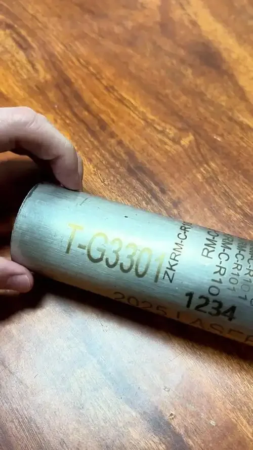
Geometry Decision Gates
Circumference, length and diameter change the marking window
A flat-looking sample is not enough for a round product. The pipe diameter, usable arc, mark height, axial position, surface runout and focus relationship all affect whether the code stays legible and in the intended location.
Circumferential marking
Use when text, a code or an identification band must follow the outside diameter. Confirm the required arc or full circumference, start position, overlap behavior and how the tube is indexed.
Lengthwise marking
Use when the mark follows the pipe axis. Confirm the available straight run, product support, focus stability, mark orientation and whether the tube moves through the marking window.
Diameter and runout
Roundness, diameter variation and wobble can move the surface away from focus or shift the mark position. Measure the actual product range before treating a recipe as repeatable.
Application boundary: this page owns the geometry and placement question. The detailed rotary axis, chuck, rollers, encoder, trigger and synchronization design belongs to the relevant solution route.
Mark Content
The code and its position define what the pipe process must prove
A short logo and a long traceability string create different marking windows. Define the message, code type and placement before comparing equipment directions.
| Requirement | Examples | What to validate |
|---|---|---|
| Content | Logo, grade or size identifier, lot, date, serial number, QR or Data Matrix code | Character height, cell size, message length, data change and reader distance |
| Placement | Axial line, circumferential band, defined arc or end-region mark | Reference edge, start angle, axial offset, repeatability and allowable drift |
| Product range | One diameter or multiple diameters and wall constructions | Recipe changeover, focus range, support method and worst-case sample |
| Downstream exposure | Handling, bending, forming, cutting, cleaning, coating or installation | Readability after the actual process and any visual, dimensional or surface criteria |
Part Presentation
Choose the presentation around the pipe movement, not a generic rotary label
The same pipe task can be presented as a stationary part, a rotated part or a continuously moving product. Each presentation changes the information required for a feasible review.
Static with controlled rotation
Suitable when the pipe can be located and rotated before or during marking. Review diameter range, support, datum, rotation indexing and the required circumferential coverage.
Review rotary and circumferential solution →Lengthwise static marking
Suitable when the product is held in a repeatable position and the mark follows the axis. Review the usable straight area, focus height, fixture clearance and mark orientation.
Review fiber machine direction →Moving or online pipe marking
Suitable when the pipe travels through a line or process station. Review speed range, product detection, trigger reference, spacing, line direction and recovery behavior.
Review flying and online solution →Do not over-read the route: a link to a solution or product page is a handoff for method and specification. It is not a promise that every pipe geometry is supported without sample testing.
Scope Boundary
Pipe application, metal behavior, system method and machine specification stay separate
A pipe inquiry can touch several page families. Keeping the ownership clear makes the next decision more useful and prevents an application page from claiming a material result, an integration case or a product specification.
Applications
This page owns the product task. Mark content, circumference or lengthwise placement, diameter and handling context, throughput inputs and acceptance requirements.
Back to Wire, Cable & Tubing →Materials
Materials own substrate behavior. Steel, stainless steel, coatings and other surface conditions need their own response review and sample record.
Browse metal materials →Solutions & Products
Solutions own the method; products own specifications. Rotary mechanics, online synchronization, source options, power, field size and confirmed machine data belong to those routes.
Open solution route →Technology Direction
Start with the metal surface, mark effect and geometry before selecting a source
Fiber is often a direction considered for metal pipe work, but the application decision should be made from the actual surface, effect and presentation. CO2 or UV may be relevant for selected coatings, treated surfaces or special requirements. The final direction remains sample dependent.
| Direction to evaluate | When it may be relevant | Application checks | Ownership handoff |
|---|---|---|---|
| Fiber / MOPA | Common direction to evaluate for selected bare or treated metal surfaces and durable identification marks. | Surface state, required contrast, mark width, heat effect, curvature, focus and downstream exposure. | Product pages own confirmed machine specifications; material pages own substrate response. |
| CO2 | Selected coatings, paints, labels or non-metal surface layers when the available wavelength is absorbed appropriately. | Layer response, residue, coating removal target, smoke/fume handling and readability after exposure. | Material and coating behavior must be checked on the real surface. |
| UV | Special surface or heat-sensitive marking requirements where a smaller affected area may be useful. | Absorption, contrast, edge quality, affected area, curvature and production presentation. | Requires sample testing; do not infer a production result from source category alone. |
Sample Validation
Validate the pipe range and presentation, not only one attractive mark
A feasibility review should reproduce the geometry and handling that the production process will use. One flat or hand-positioned sample cannot prove a rotating or online application.
- Representative parts: include the smallest and largest diameter, actual surface state, wall construction and any coating variation.
- Geometry: confirm mark arc or length, axial position, start angle, orientation, focus height and allowable placement drift.
- Presentation: test static, rotating or moving conditions as applicable, including support, wobble, product spacing and line speed range.
- Content: use the longest message, smallest feature, real code data and required reader or inspection setup.
- Downstream test: check readability and surface condition after the handling, forming, cutting, cleaning or coating process that follows.
- Release record: document sample ID, recipe version, acceptance criteria, changeover rules and any open evidence gap.
What Zhuorui needs: pipe drawings or photos, outside diameter and length range, surface/coating details, sample pieces, mark file, target location, static/rotary/online presentation, speed or rotation range, available line signals and acceptance tests.
These inputs support a quotation and feasibility review. They do not replace a documented sample result or turn a generic machine direction into a unsupported production result.
FAQ
Metal pipe and tube marking questions
Can a laser mark around the full circumference of a metal pipe?
It may be possible when the pipe can be rotated or presented through a suitable marking system. The required arc, diameter range, start position, surface condition, mark content and acceptance tolerance must be tested on representative parts.
What is the difference between lengthwise and circumferential marking?
Lengthwise marking follows the pipe axis, while circumferential marking follows an arc around the outside diameter. They create different focus, positioning, indexing and support requirements, especially when diameter or runout varies.
Does the material page or this page decide whether steel can be marked?
This page owns the pipe application and its geometry, content and acceptance needs. The relevant metal or coating page owns substrate behavior. Feasibility is confirmed by testing the actual grade, finish and surface condition.
Do I need a rotary axis for pipe marking?
Not every pipe task needs the same rotary arrangement. A controlled rotation route may be relevant for circumferential marks, while an axial or online presentation may suit lengthwise marking. The correct method depends on product handling and the required mark path.
Can metal pipes be marked while moving?
They may be, when the line provides a stable product reference and the marking window is compatible with speed, spacing, position and content. Trigger, encoder, PLC and synchronization details belong to the Flying & Online Laser Marking Solution route.
What should I send for a pipe marking review?
Send pipe samples, drawings or photos, diameter and length range, surface or coating information, mark content and dimensions, target position or arc, presentation method, speed or rotation range, inspection method and downstream acceptance tests.
Next Step
Start with the pipe, the mark path and the presentation
Share the actual pipe geometry and acceptance conditions before committing to a machine direction. Zhuorui can review the application inputs, identify the required solution handoff and structure a sample test without claiming an unsupported result.
Prepare for review: pipe samples, diameter and length, grade or surface/coating details, mark file and size, circumference or lengthwise location, static/rotary/online presentation, speed or rotation range, product support, inspection method and downstream exposure.