
Rotary Marking · Coating Removal · Personalized Drinkware
Tumbler and Cup Laser Marking
Plan laser marking for tumblers, cups and cylindrical drinkware by defining the workpiece, surface, required mark, rotary geometry, production pattern and acceptance criteria before sample testing determines the final machine configuration.
Product / Workpiece Scope
What Kind of Tumbler or Cup Are You Marking?
Start with the physical drinkware, not the laser. Define two separate dimensions first: the body geometry that controls positioning and rotation, and the surface construction that controls how the laser interacts with the finished cup.
Body Geometry
Define the shape and obstructions before deciding how the cup will be supported, oriented and rotated.
Straight-sided tumblers and travel cups
These are the simplest rotary workpieces, but the actual marking diameter, runout, surface friction and axial stop still control positioning and focus consistency.
- Measure the diameter at the real marking zone
- Define the usable axial marking height
- Identify a stable loading and stop reference
Cups with changing diameter
A tapered wall changes the surface relationship through the marked height. The taper must be treated as a workpiece input before wrap artwork or rotary motion is approved.
- Provide top and bottom diameter of the marked zone
- State marked height and angular coverage
- Define permitted graphic distortion
Workpieces with clearance constraints
Handles, weld seams, lids, bases and raised features can restrict rotation or define the visible front of the product. Their position must be repeatable during loading.
- Define the customer-facing front
- State handle and seam position
- Confirm rotary and fixture clearance
Surface Construction
Define the actual layer the laser must change and the layer that must remain acceptable after marking.
Coated, painted, anodized, bare or polymer surfaces
Powder coating, paint, anodized finishes, bare metal and polymer surfaces do not require the same process. Record the actual surface layer, color, supplier and batch when they can change the result.
- Identify the substrate when known
- Identify the surface finish or coating
- Test the finished cup rather than a flat coupon
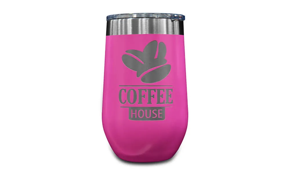
Why Mark
Why Are Tumblers and Cups Laser Marked?
The marking task should be defined by what the finished drinkware must do or communicate. The laser process is then selected to create that result on the actual surface.
Names, initials and custom artwork
One-off and short-run drinkware often needs variable names, monograms, logos or event graphics. The process must preserve spelling, orientation, scale and repeatability while the artwork changes from item to item.
Logos and decorative graphics
Retail, corporate and promotional drinkware may need a controlled surface mark or selective finish removal. The target is not simply visible contrast; edge quality, exposed surface appearance and placement must also be acceptable.
Codes, batches and variable data when required
Some drinkware projects include QR codes, batch references or other identifiers. When machine-readable content is used, the data source, code size, curved placement and verification method become part of the application.
Marking Content
What Is Commonly Marked on Tumblers and Cups?
| Marking task | Typical use | Production input | Acceptance check |
|---|---|---|---|
| Name, initials or monogram | Individual personalization | Font, spelling, size, orientation and usable zone | Correct artwork, position and appearance |
| Logo or brand graphic | Retail, corporate or promotional drinkware | Vector artwork, minimum feature, finish and placement reference | Edge quality, completeness and consistency |
| Partial-wrap artwork | Large decorative graphics | Angular start, coverage angle and distortion tolerance | Continuous appearance across the marked arc |
| Full-circumference design | Wraparound personalization | Circumference, start/end relationship, join rule and rotary reference | Join alignment, focus consistency and no visible closure step |
| QR code, batch or asset identifier | Optional traceability or campaign content | Data source, code size, reader and verification rule | Correct data and required readability on the curved surface |
Result Variables
What Determines the Laser Marking Result?
A tumbler is not defined by material name alone. The result comes from the interaction between the surface construction, geometry, artwork and production requirement that the sample test must reproduce.
Substrate, coating and finish
Record the substrate when known, coating or finish type, color, supplier and relevant batch variation. Coating thickness, pigment, cure, adhesion and the underlying finish can change removal behavior and exposed appearance.
Diameter, taper and obstruction
Geometry determines whether the cup can remain centered, in focus and correctly aligned through the marking motion. Diameter, taper, runout, obstructions and support are examined in detail in the rotary-geometry section below.
Coverage, detail and target effect
Define whether the job is a local name, fine logo, partial wrap, full circumference, code or coating-removal graphic. Include minimum features, mark size and the intended surface appearance.
Volume, cycle and changeover
State order mix, batch size, target cycle, changeover frequency, loading method, operator involvement and inspection requirement. These inputs affect the final system just as much as the laser-on time.
Target Result
What Should an Acceptable Tumbler or Cup Mark Achieve?
Define the acceptance standard before comparing laser routes. A visually strong first sample is not enough if the artwork, alignment, exposed surface or repeatability does not meet the real production requirement.
Artwork accuracy
Define: correct file, spelling, variable data, scale and minimum feature.
Check: graphic completeness with no wrong-name or wrong-data release.
Position & orientation
Define: the datum relative to handle, seam, logo, rim, base or fixture stop.
Check: repeatable location and orientation across multiple loads.
Edge & detail quality
Define: required small-detail retention and edge definition.
Check: no unacceptable ragged edge, missing detail or excessive redeposition.
Surface appearance
Define: the desired contrast or exposed-surface appearance.
Check: no unacceptable haze, discoloration, residue, texture or substrate change.
Wrap continuity
Define: coverage angle and permitted start/end mismatch.
Check: continuous appearance with acceptable join alignment.
Use durability
Define: the relevant handling, wiping or cleaning requirement.
Check: the mark again after the agreed handling or cleaning test.
Code readability, when required
Define: reader, code size and verification rule. Check: required readability on the actual curved surface rather than on a flat reference.
Cup Geometry
How Do Diameter, Taper and Obstructions Affect Rotary Marking?
Use a stable rotational reference
A straight-sided tumbler is the simplest rotary case, but nominal diameter alone is not enough. Measure the actual marking diameter and check runout, surface friction and axial location on the finished product.
- Measure at the real marking zone
- Identify a repeatable axial stop
- Check for slippage during rotation
Account for changing diameter
A tapered wall changes the surface relationship across the marked height. Provide the diameters at the upper and lower limits of the marking zone, then test artwork mapping and focus consistency on the real cup.
- Provide both marking-zone diameters
- Provide marked height and coverage angle
- Approve permitted graphic distortion
Protect clearance and orientation
Handles, weld seams, lids, bases and raised features can limit rotation or define the visible front. Loading must keep those features clear and reproduce the same orientation for each part.
- Define the customer-facing front
- State handle and seam position
- Confirm support and rotary clearance
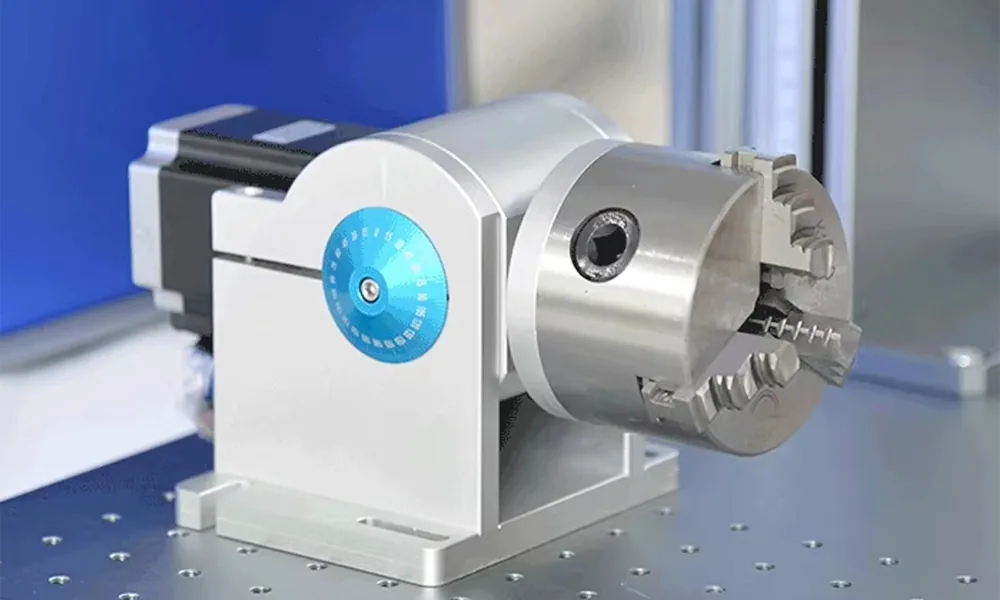
First-Test Laser Route
Which Laser Should Be Tested First?
Do not choose a laser from the word “tumbler” alone. Start from the layer that must be changed, the layer that must be preserved and the result that must be accepted. When the coating stack is uncertain, a short comparative screen is more reliable than assuming one universal source.
| Workpiece / target | First test direction | Why start there | What decides whether to continue |
|---|---|---|---|
| Bare stainless steel or other metal; direct surface mark | Fiber / MOPA fiber | Start with direct metal interaction and use pulse control, where available, to tune the required contrast and surface effect. | Contrast or appearance, heat tint, edge definition, usable process window and cycle requirement |
| Powder-coated or painted metal; remove the outer finish and preserve the base surface | Screen CO2 and/or Fiber/MOPA according to the coating stack | The target layer is the coating rather than the word “metal.” If coating composition or thickness is uncertain, compare selective removal behavior on the real cup instead of assuming one route. | Complete removal, clean edge, residue level, exposed-surface appearance and absence of unacceptable substrate change |
| Heat-sensitive polymer or plastic drinkware; fine surface mark | UV as an early screen when low visible heat effect is important | The first test should prioritize the required surface response and detail without assuming that all plastics behave alike. | Contrast, edge quality, discoloration, melting or deformation, odor/residue and required cycle |
| Nonmetal surface or decorative layer with uncertain response | Compare UV and CO2; include Fiber/MOPA only when the substrate or target effect justifies direct 1064 nm interaction | Unknown coatings and polymers should be screened by actual response, not selected from a generic material label. | Stable appearance across representative samples, acceptable thermal effect and sufficient production margin |
Failure Diagnosis
What Commonly Goes Wrong in Tumbler and Cup Marking?
A failed sample is useful when the visible symptom is connected to the variable that should be checked next. Diagnose the workpiece, process and rotary setup separately instead of increasing power by default.
| Observed problem | Likely variables to check | What to verify next |
|---|---|---|
| Patchy or incomplete coating removal | Coating thickness, pigment, cure, focus, energy delivery and scan overlap | Compare representative colors/batches and confirm whether the process window removes the coating without overworking the base surface |
| Exposed metal is darkened, hazy or visibly changed | Excess interaction with the substrate, pulse condition, repeat passes or focus | Reduce unnecessary substrate exposure and reinspect the cleaned surface under the same lighting standard |
| Edges are ragged or fine details disappear | Spot size, focus, artwork feature size, pulse/scan overlap and coating behavior | Run a controlled detail test before approving the production artwork |
| Wrap start and end do not align | Actual circumference, artwork mapping, rotary slippage, datum and start position | Measure the real cup, confirm rotational repeatability and repeat the closure test |
| Focus or line quality changes through a tapered marking zone | Changing diameter, marked height, support alignment and rotary motion | Test the upper and lower limits of the actual marked area rather than only the center |
| Correct mark quality but wrong name, logo or orientation | File selection, variable-data control, loading reference and changeover procedure | Verify job release, part identification and first-piece inspection before continuing the batch |
Production Workflow
What Must the Production Marking Workflow Include?
Production readiness is more than laser-on time. The repeatable cycle starts with the correct cup and artwork, controls loading and orientation, verifies the finished mark and defines what happens when the product or personalization changes.
Release the job
Confirm cup variant, artwork version, spelling or variable data, mark size and order quantity.
Why: prevents the wrong file or wrong product from entering the marking cycle.
Load and orient
Locate the cup against the defined stop and orient the handle, seam or visible front.
Why: creates a repeatable position before rotation or marking starts.
Set the process condition
Confirm diameter/taper input, focus, rotary reference and the approved process setting.
Why: separates setup control from the mark itself and makes changeover reproducible.
Mark and inspect
Check artwork completeness, position, edge quality, surface condition and wrap alignment.
Why: stops a process problem from continuing through the batch.
Clean or handle as required
Apply the agreed post-mark cleaning or handling check when it is part of acceptance.
Why: confirms the approved appearance remains acceptable after the relevant use step.
Accept, reject or rework
Define first-piece approval, reject criteria, rework rule and the trigger for a new setup check.
Why: turns inspection into a usable production decision rather than a visual comment.
Sample Qualification
How Should Representative Tumbler Samples Be Qualified?
A sample test should represent the real order mix, not only one easy cup. The qualification set must cover the conditions that can change marking quality, rotary stability or production repeatability.
1. Build a representative set
Include each relevant cup shape, marking diameter, taper, coating or finish, color, supplier/batch variant and obstruction that can change the result.
2. Test real artwork and data
Use the actual logo, smallest required details, names or variable data, mark size, orientation and partial- or full-wrap coverage. Compare process conditions in a controlled matrix.
3. Inspect result and repeatability
Check appearance, edge quality, position, wrap closure, exposed surface, handling or cleaning response when relevant, then repeat on more than one representative workpiece.
4. Lock the accepted condition
Keep an approved master sample and record the accepted workpiece, process window, rotary setup, inspection rule, changeover requirement and measured cycle before equipment is finalized.
Final Machine Configuration
How Do Sample-Test Results Determine the Final Machine Configuration?
The final system should be a consequence of the accepted sample process. Each important test finding should map to a laser, rotary, fixture, data-control or production requirement instead of being converted directly into a model number.
| What the sample test establishes | What it determines in the final configuration |
|---|---|
| Which laser route creates the required surface effect | Laser source family and required pulse-control capability |
| The usable process window and cycle margin | Required power/control range, optics and production headroom rather than selecting by nominal wattage alone |
| Actual diameter, taper, runout and workpiece length | Rotary method, chuck/roller/support arrangement and fixture adjustment range |
| Handle, seam, lid or base interference | Loading orientation, clearance, support and fixture design |
| Local mark, partial wrap or full circumference requirement | Whether simple fixed positioning is enough or controlled rotary motion is required |
| Frequency of cup-size, coating or artwork changeover | Fixture adjustability, setup method, saved recipes and operator changeover procedure |
| Personalized or variable data workflow | File/data input, job-selection control and any verification step required before release |
| Measured complete production cycle | Manual, semi-automatic or more automated loading direction and the required productivity margin |
| Positioning and inspection tolerance | Fixture precision and, when the workflow requires it, additional positioning or verification functions |
Next Step
Prepare a Tumbler or Cup Marking Test
Share the actual drinkware, surface finish, artwork, geometry, production pattern and acceptance standard. The sample test should identify the workable laser route, prove the rotary and fixture condition, establish repeatability and provide the inputs needed for the final machine configuration.
Prepare: representative cup samples; substrate and coating/finish information; actual marking diameter and taper; handle or seam position; final artwork and personalization data; mark size and coverage; batch size and changeover pattern; target complete cycle; inspection, handling or cleaning requirements; destination and voltage.