
PV Module Frames · Junction Boxes · Durable Identification
Solar Component Laser Marking
Define a laser marking process for PV module frames, rails, junction-box housings and selected related hardware by starting with the real surface, mark requirement, part geometry, production flow and acceptance criteria. The goal is not simply to make a visible mark, but to qualify a repeatable identification process that can survive the component’s expected handling and service conditions.
Product Scope
Which Solar Components Does This Page Cover?
This page focuses on permanent identification and traceability tasks on PV module frames, rails, junction-box housings and covers, plus selected brackets, plates and related hardware. These parts can share a qualification workflow, but they do not share one universal laser setting because the substrate, coating, geometry and required mark effect are different.
PV module frames and rails
Typically aluminum profiles with bare, anodized, painted or other treated surfaces. Marking tasks can include part identity, lot or serial information, orientation and a code associated with the assembled module.
Junction-box housings and covers
Usually compact molded polymer parts with limited marking zones around cables, connectors, seals and electrical interfaces. Resin, color, additives and surface texture can change the laser response.
Selected related hardware
Brackets, plates, nameplates and other identification areas can follow the same decision path when the mark must remain readable without interfering with assembly or function.
Why Mark
Why Are Solar Components Marked?
The marking task normally exists because a component must be identified, assembled correctly, linked to production data or recognized later in inspection and service. Laser marking is evaluated only after that business and production requirement is clear.
Marking Content
What Information Is Usually Marked?
Freeze the information requirement before process development. A high-contrast mark is not useful if the payload, code size, position or verification rule is still changing.
| Content type | Typical use | What must be defined before qualification |
|---|---|---|
| Human-readable text | Part number, supplier code, model, date, lot or installation reference. | Character height, font, final position, inspection distance and minimum acceptable readability. |
| QR or Data Matrix | Serial, lot, work-order or production-record lookup. | Payload, physical code size, cell size, quiet zone, production scanner and verification method. |
| Polarity or orientation | Reduce assembly ambiguity at electrical or mechanical interfaces. | Approved symbol, orientation relative to the finished assembly and protected keep-out areas. |
| Customer or compliance identification | Required component information where a drawing or specification calls for permanent identification. | Approved wording, location, ownership of logos or marks, and the required permanence test. |
Result Variables
What Determines the Marking Result?
The component name alone does not define the process. The qualification sample must represent the production material, surface, code geometry and handling condition because each of these variables can change contrast, edge quality, durability and cycle time.
| Variable | PV frame / rail | Junction box / related part |
|---|---|---|
| Material and surface state | Aluminum grade and whether the mark zone is bare, anodized, painted, powder-coated or otherwise treated. | Polymer family, color, additives, molded texture, label or coating condition. |
| Required mark effect | Surface contrast, controlled layer change, shallow engraving or another customer-defined result. | Color change, foaming, surface modification or another acceptable effect without unacceptable melting or charring. |
| Code and feature size | Text height, line width, 2D-code size and required marking field. | Small characters, Data Matrix cell size, spacing and readability near molded features. |
| Geometry and focus | Long profile length, datum, flatness, height variation, number of mark positions and edge distance. | Curvature, molded ribs, connector or cable protrusion, available flat zone and part orientation. |
| Keep-out and downstream interfaces | Fasteners, bonding areas, seals, inspection surfaces and assembly contact zones. | Cable exits, connectors, seals, terminals and customer-defined no-mark areas. |
| Production demand | Volume, takt time, loading method, indexing distance and changeover frequency. | Tray or fixture loading, orientation control, code data handoff, inspection and reject handling. |
Target Result
What Should a Qualified Mark Achieve?
The acceptance criteria should be defined before the laser is selected. Qualification is based on whether the real part reaches the required result, not on whether a sample simply looks dark immediately after marking.
Geometry & Loading
How Do Part Shape and Loading Change the Marking Setup?
A process can make a good mark on one sample and still fail in production if the real part cannot be located, supported, focused or moved repeatably.
Stationary component
Setup questionCan the fixture reproduce the datum, orientation and mark-zone position for every part?
Configuration impactFixture design, working distance, marking field and operator access.
Long frame or rail
Setup questionHow is the profile supported, indexed or moved while keeping the mark zone inside the qualified focus and field?
Configuration impactTable length, support, Z clearance, linear/indexing motion and multiple-position strategy.
Junction box with cables or protrusions
Setup questionCan the housing be located without cable, connector or seal interference?
Configuration impactNest/fixture design, workstation clearance, Z travel, working distance and possible vision assistance.
Variable orientation or mark location
Setup questionIs a fixed datum sufficient, or must the system locate the actual part or code zone before marking?
Configuration impactMechanical poka-yoke, camera positioning, recipe control and verification.
Inline production
Setup questionHow are parts triggered, presented, marked and removed within the required takt time?
Configuration impactMotion, sensor/PLC interface, scanner placement, reject handling and automation level.
First-Test Laser Route
Which Laser Direction Should Be Screened First?
Use the actual component and target effect to choose the first screening route. The purpose of the first trial is to eliminate unsuitable process directions quickly, not to assume that one source will cover every frame and junction box.
| Condition | First screening direction | What the trial must answer |
|---|---|---|
| Bare or treated aluminum frame / rail | Start with an appropriate fiber-laser trial for the required metal or surface-layer effect. If the acceptance window benefits from greater pulse-width control or a wider controllable process window, compare a suitable MOPA fiber configuration. | Can the required contrast or surface change be produced without unacceptable heat tint, coating damage, depth or cycle-time penalty? |
| Heat-sensitive or very small polymer code | Include a UV trial early when minimizing the affected area or preserving fine feature definition is a key requirement. | Does UV improve edge definition and surface quality enough to justify the required configuration and cycle time? |
| Polymer formulated to respond to near-IR marking | Include a suitable fiber-laser trial on the exact resin, color and additive combination instead of selecting only by the word “plastic.” | Is the color change or surface effect stable across representative molded parts without excessive melting, charring or weak contrast? |
| CO2-responsive polymer, label or surface layer | Evaluate CO2 only where the actual material and desired effect make it a plausible process route. | Does the result meet detail, readability and surface-damage requirements better than the alternative routes? |
| Good mark quality but unstable placement | Do not change the laser source first. Check fixture datum, focus recovery, part orientation and whether vision positioning is needed. | Is the failure caused by process physics or by locating and handling the workpiece? |
Failure Modes
Where Can Solar Component Marking Fail?
Diagnose the observed failure before increasing power or changing machines. Similar-looking defects can come from different causes, so the fastest route is to separate surface-response problems from positioning, data and production-control problems.
| Failure group | Observed symptom | Evidence that helps separate the cause | First check |
|---|---|---|---|
| Frame surface | Low or inconsistent contrast across nominally similar frames. | Compare actual anodized/coated condition, supplier batch, cleaning state and the same parameter set on retained samples. | Confirm the production surface before changing laser settings. |
| Frame surface | Halo, heat tint, excessive layer removal or depth. | Inspect the affected zone, coating boundary and cross-part repeatability; compare lower-energy or different pulse-control trials. | Determine whether the process window is too aggressive for the required surface effect. |
| Junction-box polymer | Weak contrast, uneven color change or batch-to-batch variation. | Record resin family, color, additive package, molded texture and supplier/batch differences. | Re-test representative production molding instead of assuming one polymer result transfers to another. |
| Junction-box polymer | Melting, charring, foaming or closed 2D-code cells. | Inspect feature edges and code cells under the same magnification; compare wavelength and process-window candidates. | Separate excessive thermal effect from insufficient optical response. |
| Position / focus | Mark quality changes by location or the code drifts outside the approved zone. | Check datum repeatability, part height, working distance, indexing position and fixture play. | Verify location and focus before changing source power. |
| Data / production | Correct-looking marks contain wrong, duplicate or unverifiable data. | Trace the data source, trigger, recipe, scanner result and exception log for the affected parts. | Check data handoff and verification logic, not the optical mark alone. |
| Post-exposure durability | The mark passes initial inspection but loses readability, contrast or surrounding-surface integrity after the required UV, thermal, moisture, cleaning or handling exposure. | Compare the same representative sample before and after each specified exposure, including images or scanner results, and separate true mark degradation from contamination or a change in the surrounding coating. | Identify which exposure or cleaning step correlates with the degradation before changing the laser source or process window. |
| Cycle time | Sample quality passes but the process misses takt time. | Separate actual marking time from loading, positioning, data, verification and motion time. | Identify the station bottleneck before increasing laser power or adding automation. |
Production Workflow
What Must the Production Marking Workflow Include?
Moving from a good sample to a production process means controlling part presentation, data, marking, verification and exceptions as one sequence.
Load and present
Support the frame, rail, housing or related part so the production mark zone is accessible without interfering with cables, seals or fixtures.
Confirm identity and orientation
Use mechanical features, operator confirmation, sensors or vision as needed so the correct part and side are presented.
Locate the mark zone
Recover the datum, working distance and focus, then position or index the part so the approved zone is inside the qualified field.
Receive data and mark
Load the correct part code, serial, lot, work-order or other approved payload and execute the qualified marking recipe.
Verify and route the part
Check required readability, code verification, position or other acceptance items and define what happens to a failed part.
Record and change over
Store the required result or traceability record, then control recipe, fixture, datum and first-off confirmation when the product changes.
Traceability is a workflow, not just a code
If the mark must connect a component to a work order, assembled module, inspection record or service history, define the data source, handoff, verification and exception path before finalizing the machine.
Where a project requires deeper data integration, review the traceability data integration solution.
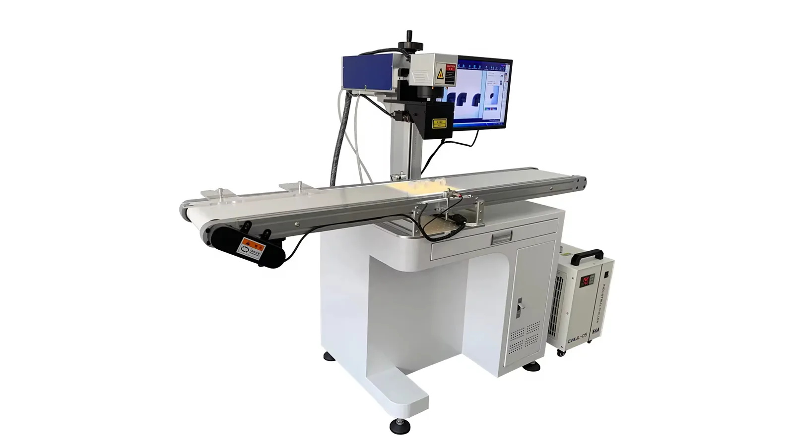
Sample Qualification
How Should Representative Solar Components Be Qualified?
Qualification should reproduce the production surface, real mark content, actual mark zone and the checks that matter after marking. It should also show whether the process remains acceptable after the exposures defined for the application.
- Collect representative parts. Include the production material, coating or resin state, plus meaningful supplier, batch or color variation where it exists.
- Freeze the proposed mark. Use the real text or code size, mark zone, keep-outs and intended production scanner or inspection method.
- Screen candidate process windows. Change one relevant variable at a time and record the source, optics, settings, fixture and observed result.
- Inspect the initial result. Check readability, code quality where required, position, edge definition, residue, heat effect and any surface damage.
- Apply required durability or environmental exposure. Depending on the customer’s specification and service environment, this may include UV exposure, temperature or thermal cycling, humidity/moisture, cleaning/wipe procedures, abrasion or handling.
- Re-inspect after exposure. Re-check human and machine readability, contrast, mark-zone integrity and any change to the surrounding surface.
- Confirm repeatability. Repeat the selected process on representative parts, positions and changeovers rather than approving a single best-looking sample.
- Freeze the qualified sample and process window. Record the acceptance criteria and use the result to define the production machine configuration.
No universal outdoor test threshold
UV hours, temperature cycles, cleaning agents, abrasion levels and pass/fail limits should come from the customer requirement, product specification or validated service condition. This page defines what must be checked; it does not invent one durability threshold for every solar component.
Part drawings or photos, material/coating or resin details, mark content, code size, approved keep-outs, part envelope, expected volume, takt time, loading method, scanner target and required downstream or environmental checks.
Final Machine Configuration
How Do Test Results Determine the Final Machine Configuration?
Do not choose the final machine from the component name alone. Each qualified test result should resolve a specific configuration decision.
| What the test establishes | Configuration decision it drives |
|---|---|
| Which wavelength and pulse behavior produce an acceptable mark on the real surface | Laser source and pulse-control requirement, including whether a standard fiber route, MOPA fiber, UV or another qualified source is needed. |
| Required detail, code cell size, marking field and working distance | Lens / optics / marking field and the working distance needed to keep the part inside the qualified process window. |
| Part datum and repeatable mark position | Fixture design, poka-yoke features and whether a fixed mechanical location is sufficient. |
| Part height, frame profile, cable protrusion and largest workpiece envelope | Z travel, workstation clearance, table layout and loading access. |
| Long frames, multiple mark positions or moving parts | Indexing, linear motion, rotary/motion strategy or online synchronization as required by the production flow. |
| Position variation that cannot be controlled reliably by fixture alone | Vision positioning and the camera field / correction strategy required for the approved mark zone. |
| Machine-readable code and required verification method | Scanner or vision verification, including where verification occurs in the cycle and how failed reads are handled. |
| Dynamic serial, lot, work-order or module data requirement | PLC / MES / database interface, trigger logic, recipe/data handoff and traceability record requirements. |
| Measured marking time plus loading, positioning, verification and handling time | Throughput and automation level. The final station should be sized from the total cycle, not from laser scan speed alone. |
Solar Component Review
Define the part, target result and qualification method before selecting the machine
Share the actual PV frame, rail, junction box or related component together with its material or surface, proposed mark, keep-outs, part envelope, volume and acceptance requirement. The sample result can then be used to define the laser source, optics, fixture, motion, verification and production configuration.