
Cable Identification · Connector Traceability · Readability Validation
Aerospace Cable and Connector Laser Marking
Define the marked part, identification purpose, material and surface, usable zone, inspection method, handling sequence and production requirement before selecting a laser. Representative sample testing should then determine the source, optics, fixture, motion, vision and data functions required for production.
Quick Answer
Start with the actual cable, sleeve, connector or finished harness—not the laser model. Define the identification purpose, material/surface, usable mark zone, production state, inspection rule and required handling or exposure, then use representative samples to qualify the process and final machine configuration.
Product Scope
What Aerospace Cable and Connector Parts Are Being Marked?
Start with the actual workpiece and its production state. The same identification requirement can behave differently on a loose wire, a finished harness, a polymer sleeve or a plated connector shell.
Insulated conductors and jacketed cable
Single wires, jacketed cables and other wire constructions where identification is applied directly to the insulation or outer jacket.
Heat-shrink and external markers
Sleeves used when direct jacket marking is unsuitable, when a dedicated readable zone is needed or when identification is applied at a termination.
Connector shells and backshells
Metal, plated or coated hardware with curved surfaces, keyways, threads, seals and mating interfaces that constrain the usable mark zone.
Cable and harness assemblies
Completed assemblies where bend, bundle position, connector orientation and inspection access can change whether the final identifier remains readable.
Why Mark
Why Are Aerospace Cables and Connectors Marked?
The mark is part of identification, assembly, inspection and maintenance control. It should help a person or system identify the correct wire, circuit, connector or assembly without creating an unacceptable change to the product.
Installation and circuit identity
Wire and cable identifiers help installers relate the physical wiring to the drawing, circuit or harness position and reduce ambiguity during assembly.
Maintenance and replacement
Readable part and circuit identification helps technicians confirm the correct item during inspection, troubleshooting or replacement instead of relying on appearance alone.
Traceability and inspection
Part, serial, lot, orientation or assembly references can connect the physical component to inspection and production records where the controlling program requires that relationship.
For scope context, NASA-STD-8739.4A includes permanent cable/harness and connector identification requirements for NASA workmanship, while FAA AC 43.13-1B discusses wire identification in aircraft inspection and repair. These are context-specific references, not universal specifications for every aerospace program.
Mark Content
What Information Is Usually Marked?
Freeze the actual field definitions before testing. Appearance, data correctness and record association should be reviewed together; a visually clean mark with the wrong identifier is still a failed identification process.
| Marked object | Typical content | What the content supports |
|---|---|---|
| Wire or cable jacket | Wire ID, circuit reference, part number, lot/date code, repeated identification | Installation, circuit recognition, maintenance and production association |
| Identification sleeve | Harness position, terminal reference, part number, serialized or replacement information | A readable identification zone when direct jacket marking is unsuitable or inaccessible |
| Connector shell / backshell | Part number, mating reference, serial number, orientation mark, compact code | Hardware identification, orientation and traceability |
| Completed harness / assembly | Harness, batch, inspection or replacement reference | Association between the finished assembly and its production or inspection record |
Result Variables
What Determines the Laser Marking Result?
“Aerospace cable” or “connector” is not enough information to select a process. The result depends on the actual material system, geometry, mark requirement, production state, production requirement and inspection method.
| Variable | What to define | Why it changes the result |
|---|---|---|
| Material and surface | Polymer family, pigment, additives, jacket construction, base metal, plating, anodizing, paint or other coating | Changes absorption, contrast mechanism, thermal response and whether the surface may be altered |
| Mark requirement | Text, code, minimum feature, line spacing, contrast, depth or prohibited surface change | Determines the process window and whether a visually acceptable effect is functionally acceptable |
| Geometry | Cable diameter, curvature, knurling, keyways, threads, recesses and available zone | Changes focus, optical access, character distortion and fixture requirements |
| Production state | Continuous wire, cut length, loose connector, terminated cable, finished harness or installed orientation | Changes presentation, datum control, motion and the point at which readability must be verified |
| Production requirement | Batch size, production volume, line speed, required takt, changeover range and automation level | Determines whether the qualified process can remain stationary or needs flying, indexed, fixture-based or automated handling without sacrificing the accepted process window |
| Post-mark process | Shrinking, cleaning, termination, bending, bundling, mating, abrasion or specified environmental exposure | A mark that looks acceptable immediately after marking can fail after the real production or service sequence |
| Inspection and data | Human-readable criteria, reader/lighting, decoded data, variable-data source and reject rule | Defines how the result is measured and prevents a cosmetic appearance check from replacing functional verification |
Target Result
What Should an Acceptable Aerospace Mark Achieve?
The target is not simply a darker mark. Acceptance should combine legibility, correct information, material integrity, durability under the required sequence and repeatability across the approved variants.
Readable and correct
- Human-readable text: freeze minimum text height, spacing, orientation, contrast and viewing condition; verify complete characters remain legible after the required handling or exposure.
- Machine-readable data: freeze code content, size, quiet zone where applicable, reader, lighting and reject rule; verify correct decoding under the agreed condition. One successful scan is not production qualification.
- Identification correctness: confirm the data source, field format and association to the correct cable, connector or harness, with a defined response to unreadable or incorrect marks.
Safe and repeatable
- Material and surface integrity: define prohibited melting, charring, insulation damage, plating removal, coating lift, seal/thread damage or other unacceptable change, then verify none occurs on the actual part.
- Durability through the required sequence: recheck the mark after the specified shrinking, cleaning, bending, bundling, mating, abrasion or environmental exposure rather than judging the fresh mark alone.
- Production repeatability: confirm the accepted process window across approved diameters, colors, suppliers, finishes, positioning methods and production presentations.
SAE ARP5607B is specifically concerned with legibility of human-readable markings on aerospace wire and cable and distinguishes mark-related variables from viewing/environmental variables. It does not cover bar codes or other machine-readable symbols, so code verification still needs its own reader and acceptance rule.
Geometry and Handling
How Do Cable Diameter, Connector Geometry and Assembly Affect Marking?
Cable and wire jackets
Small diameter, curvature, color variation and limited character height can reduce clarity. Test the actual jacket construction and the smallest production diameter, not only a flat sample.
Readability should be checked in the state that matters: after bending, bundling, termination or installation when those steps are part of the qualification requirement. Mark interval and direction also affect whether an identifier remains visible on the finished harness.
Connector shells and backshells
Knurling, threads, keyways, shoulders, coatings and curved zones can limit optical access and usable marking area. The fixture must reference a repeatable datum without damaging mating, sealing or electrical interfaces.
Sleeves and mixed assemblies
Define whether identification is applied before or after shrinking, termination, cleaning, connector assembly and final inspection. A process qualified in the wrong production state may not represent the finished part.
First-Test Laser Route
Which Laser Route Should Be Tested First?
Select the first test route from the controlling wire or part requirement and the actual material construction. Do not treat every polymer cable jacket as interchangeable, and do not force one laser source to cover both polymer wire and metal connector hardware before each mark family is qualified.
Start with the specified UV route
When the drawing, wire specification or supplier documentation identifies the construction as UV-laser-markable, start with a UV laser marking qualification. SAE AS5649B applies specifically to UV laser marking of aerospace vehicle electrical wire and cable.
- Use the actual wire construction, color and diameter
- Confirm legibility and insulation integrity after the required sequence
- Do not transfer settings from an unrelated polymer coupon
Evaluate from the actual construction
For sleeves or polymer constructions that are not governed by a UV-laser-markable wire requirement, compare candidate processes from the resin, pigment, additives, geometry and prohibited thermal effect. A CO2 laser can be evaluated where the material and controlling requirement permit it, but it should not be presented as an equal default to UV for UV-markable aerospace wire.
- Test every relevant color and supplier construction
- Define allowed surface change before testing
- Reject a route that gains contrast by unacceptable damage
Evaluate a fiber route on the finished surface
For metal connector shells and backshells, evaluate a fiber laser marking route according to base metal, plating or coating, desired effect, available zone and protected interfaces. MOPA is a pulsed fiber option, not a separate wavelength family.
- Protect seals, threads and mating areas
- Confirm fixture datum and optical access
- Approve the actual finished surface, not bare base metal alone
Failure Modes
Where Do Aerospace Cable and Connector Marks Fail?
Use the failure appearance to decide what to check next. Increasing power is not a universal fix; the wrong wavelength, material assumption, focus, geometry, data workflow or production sequence can all create different failure modes.
| Observed problem | Likely variables to check first | Next verification |
|---|---|---|
| Good contrast on one jacket color but weak or unstable contrast on another | Polymer construction, pigment/additives, supplier variant, wavelength response | Repeat a controlled matrix on each production color/construction before widening the approved process window |
| Readable mark but unacceptable melting, charring or insulation change | Wavelength/material interaction, energy density, thermal accumulation, prohibited-effect definition | Re-evaluate the route and inspect the actual jacket after the required handling/exposure; do not approve on contrast alone |
| Characters clip or distort on small-diameter cable | Diameter, focus, character height, field geometry, cable presentation | Test the smallest production diameter in its real orientation and adjust optics or mark layout as needed |
| Connector mark is complete on one side but weak on another | Curvature, rotation, fixture datum, surface height, optical access | Check repeatable positioning and whether the mark zone exceeds the usable optical field on the curved surface |
| Code looks acceptable but reader verification is inconsistent | Cell size, contrast, curvature, lighting, reader angle, data quality | Verify with the production reader/lighting condition and a defined reject rule rather than visual judgment alone |
| Loose wire is readable but the assembled harness hides or distorts the mark | Mark direction, interval, bend, bundle position, sleeve/connector assembly sequence | Inspect the identifier after representative assembly and revise mark location or interval if needed |
| Correct-looking mark is associated with the wrong part or serial record | Variable-data source, job selection, verification logic, reject/redo workflow | Challenge the data workflow with controlled samples and confirm record association before production release |
Production Workflow
How Does the Marking Process Move into Production?
The production architecture follows the workpiece flow. Continuous wire needs controlled feed and mark spacing; connector hardware needs repeatable locating and orientation. Both need a defined verification and reject response.
Continuous wire or cable
- Load the correct wire construction and production job.
- Control feed, line presentation, mark interval and orientation.
- Apply the approved laser process within the qualified window.
- Verify legibility or encoded data at the agreed inspection point.
- Stop, segregate or otherwise handle an unreadable/incorrect mark according to the production rule.
- Record required batch, job or serialized information.
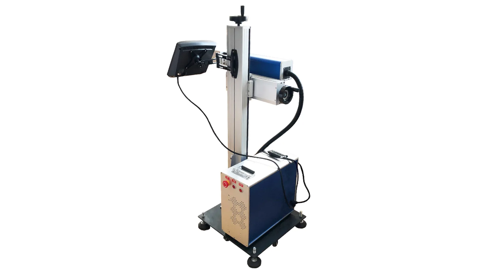
Where continuous motion is required, evaluate flying / online marking only after the stationary sample process and real line-speed requirement are understood.
Connector, backshell or batch assembly
- Load the correct part and recipe.
- Locate a repeatable datum and control rotation or presentation.
- Protect mating, sealing, threaded and electrical interfaces.
- Apply the approved mark and verify human-readable or machine-readable output.
- Separate accepted and rejected parts with the data association preserved.
- Confirm the cycle can meet production takt without narrowing the approved quality window.
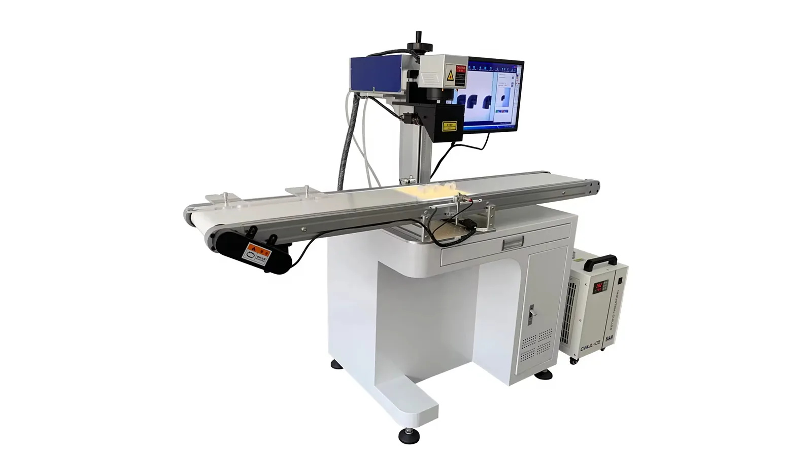
Use vision positioning or traceability data integration only when the production presentation or data flow actually requires it.
Sample Validation
How Should Representative Aerospace Samples Be Qualified?
Qualification should reproduce the real mark data, representative material variants, actual geometry, production sequence, required handling or exposure and agreed inspection method. The goal is to define an accepted process window, not to select the best-looking one-off sample.
- Freeze the requirement. Provide the controlling drawing or specification, final data, mark zone, minimum feature, prohibited effects, reader/inspection rule and the exact handling or exposure that applies to the program.
- Test real variants. Include the relevant jacket colors, diameters, supplier constructions, sleeves, base metals, plating and coatings that can change the result.
- Run the process matrix. Change the variables that need qualification while holding the sample definition and inspection method consistent. Record which combinations pass, fail or need narrower limits.
- Apply the required handling and exposure. Use only the conditions called for by the controlling requirement; aerospace does not have one universal sequence for every cable and connector program.
- Assembly: bending, bundling, pulling, termination, mating and normal tool contact where required.
- Fluids: only the cleaners, fluids or chemical exposures specified for the program or service condition.
- Temperature: the defined aging or temperature sequence, checked at the required point.
- Wear: abrasion or contact conditions that represent actual harness routing, handling and inspection access.
- Integrity: no unapproved damage to insulation, shielding, plating, coatings, seals, threads or mating features.
- Reinspect and record the accepted process window. After the full sequence, verify data correctness, human-readable legibility, machine-readable performance where applicable, material integrity and repeatability, then record the limits that may be transferred into production.
Final Machine Configuration
How Do Sample-Test Results Define the Final Machine Configuration?
The sample test should convert a marking requirement into hardware and workflow decisions. Select the machine only after the accepted process window, geometry, inspection method and production rate are known.
| Sample-test finding | Configuration decision | What still needs to be confirmed |
|---|---|---|
| UV-laser-markable wire passes across the required colors and diameters | Confirm the UV source family, optics and qualified process window | Smallest feature, field size, handling state, repeatability and production speed |
| Finished connector surface passes with a fiber process | Confirm fiber source/pulse-control requirement, optics and allowed surface effect | Plating/coating variants, curved zone, protected interfaces and production repeatability |
| Small characters or codes are marginal at the current field size | Reconsider optics, focal spot, field size and mark layout before increasing energy | Whether the revised optical setup still covers the required work area and takt |
| Cable orientation or connector rotation changes mark quality | Add or redesign cable guidance, fixture, rotary control or datum strategy | Changeover range, repeatability and operator loading method |
| Part presentation varies but the mark zone is visually identifiable | Evaluate vision positioning rather than relying on manual alignment | Height variation, field of view, cycle time and false-detection/reject behavior |
| Machine-readable or serialized data must be verified | Add the required reader, lighting, verification and data-integration functions | Data source, duplicate prevention, unreadable-code response and record retention |
| Approved mark quality cannot meet required takt | Reassess source/optics, motion architecture, loading strategy or parallel process design | Do not trade away the accepted material-integrity or readability window simply to gain speed |
Standards Context
Technical Standards and Qualification References
Use each reference only within its scope. The controlling drawing, customer specification and representative sample remain the basis for the actual project; these documents are not interchangeable approvals for one universal laser process.
- SAE International — AS5649B, Wire and Cable Marking Process, UV Laser. Revised May 2025. Applies specifically to UV laser marking of aerospace vehicle electrical wire and cable, including fiber-optic cable, and is the most directly relevant process reference for wire that is specified as UV-laser-markable.
- SAE International — ARP5607B, Legibility of Print on Aerospace Wires and Cables. Provides recommendations for human-readable legibility and the variables that influence it. It is generic to marking method and does not cover bar codes or other machine-readable symbols.
- NASA — NASA-STD-8739.4A, Workmanship Standard for Crimping, Interconnecting Cables, Harnesses, and Wiring. Relevant to NASA cable/harness workmanship. Its identification requirements are useful context for permanent, legible cable/harness and connector identification within NASA work; they should not be generalized to every aerospace program.
- Federal Aviation Administration — AC 43.13-1B, Aircraft Inspection and Repair. Includes wire-identification guidance for aircraft maintenance and repair context, including legibility and avoiding identification methods that impair wiring characteristics. It is not a universal new-production laser-marking process specification.
- U.S. Department of Defense — MIL-STD-130, Identification Marking of U.S. Military Property. Applies to identification marking criteria for U.S. military property. Use it only when the applicable DoD contract or program invokes it; it is not an aerospace cable laser-marking process standard.
Engineering Review
Prepare an Aerospace Cable and Connector Marking Review
Share representative cables, sleeves, connector shells or backshells with the controlling requirement, final mark data, readable zone, inspection method, production sequence and required takt. Zhuorui Laser can use the samples to define the first test route and translate accepted results into a machine configuration.
Prepare: drawing or specification · jacket and connector variants · material/surface details · final data · mark zone · smallest feature · reader and inspection rule · handling/exposure sequence · production state · volume and takt · destination and voltage.