
Small Characters / Curved Temples / Mixed Frame Materials
Eyewear Frame Laser Marking
Define the eyewear product, frame material and finish, marking zone, mark content, target result, part geometry, loading method and production requirement first. Then use representative frame samples to screen the laser route and determine the final marking-machine configuration.
Product / Workpiece Scope
Which Eyewear Products and Workpiece States Need Laser Marking?
This page is for marking the frame or frame components of eyeglasses and sunglasses. The first distinction is the product and workpiece state; the second is the exact zone that will be marked.
Typical eyewear products
- Prescription eyeglass frames
- Reading-glass frames
- Sunglass and fashion-eyewear frames
- Other frame styles where the actual material, finish and marking requirement can be defined
This page concerns frame marking. Lens marking needs a separate material, optical and process evaluation.
Workpiece state before marking
- Loose left and right temples before final assembly
- Frame fronts or other separate frame components
- Complete assembled frames with hinges, lenses or decorative parts nearby
- Multiple colors, finishes, sizes or supplier batches that share one production line
Loose and assembled parts can require different fixtures, focus clearance, protection and production sequences even when the artwork is identical.
Frame Zones
Where on the Eyewear Frame Will the Mark Be Placed?
Small text in a narrow usable zone
The inside of a temple commonly carries model, size, color, origin or other controlled text. Taper, curvature, hinge hardware and the finished edge can limit the usable mark height.
- Measure the real usable area
- Set minimum text and spacing
- Keep clear of hinge and contact zones
Branding with cosmetic acceptance
Outer-temple logos are visually sensitive. Position, contrast, edge quality and left-right consistency normally matter more than maximum engraving depth.
- Define open or closed orientation
- Approve the actual finish variants
- Protect polished, plated or coated surfaces
Restricted access near assembled features
Small frame areas can add height change, obstruction and sensitive adjacent parts. A loose-component result may not transfer directly to an assembled frame.
- Identify nearby lenses and hardware
- Confirm focus and head clearance
- Test the actual assembly state
Why Mark
Why Are Eyewear Frames Laser Marked?
Brand and product identity
Apply logos or controlled brand marks where a stable position, clean edge and consistent cosmetic appearance are required.
Model, size and variant identification
Keep model, frame size, color or other variant information on the correct left or right component and linked to the correct production recipe.
Customer or market text
Apply buyer-approved wording, origin text or other specified information in the required location. The customer remains responsible for the applicable content requirement.
Production traceability
Add batch, serial or compact machine-readable data when the production system requires item or lot identification and verification.
Marking Content
What Is Commonly Marked on Eyewear Frames?
| Marking content | Typical examples | Define before testing | Acceptance focus |
|---|---|---|---|
| Brand or logo | Logo, symbol or short brand name | Artwork, mark width, marked side, orientation and target appearance | Complete shape, clean edges and consistent placement |
| Model and color information | Model number, style code, color code | Data source, character set, revision rule and left-right assignment | Correct data, readable characters and no variant mix-up |
| Frame size information | Customer-specified size notation and separators | Exact notation, minimum character height, stroke and spacing | Legibility by the agreed inspection method |
| Customer or market text | Buyer-approved wording, origin text or other required information | Approved wording, placement, market applicability and revision control | Exact content and location on the finished frame |
| Batch, serial or compact code | Lot ID, serial number, small 2D code where required | Data format, uniqueness rule, code size and verification method | Correct data and readable result at the required inspection level |
Result Variables
What Determines the Eyewear Frame Marking Result?
The result is controlled by a combination of surface, mark design, workpiece geometry and production handling. Define these inputs together before comparing laser routes.
Start with the actual finished surface
Base material, coating, plating, polish, pigment, additive package and layered construction can change absorption, contrast, melting and edge behavior.
Define the smallest feature that must survive
Character height alone is not enough. Stroke width, spacing, line count, logo detail, code size and total mark width affect the process window.
Usable area and nearby features matter
Hinges, decorative parts, frame edges and lens proximity can restrict the mark position, focus clearance and allowable heat or residue.
Curvature, taper, twist and datum control focus
The same temple design can mark differently if the workpiece rolls, bends or sits at a different height in the fixture.
Loose parts and assembled frames are not equivalent
Assembly changes access, clearance, protection needs and the risk of damaging lenses, hinges, pads or decorative components.
Throughput and changeover affect the machine concept
Batch size, variants per shift, target takt time, loading method, inspection level and required automation determine whether a simple fixture or a more controlled workstation is justified.
Target Result
What Should an Acceptable Eyewear Frame Mark Achieve?
Define success before testing. A readable mark is not acceptable if position, cosmetic finish or frame integrity falls outside the agreed requirement.
Readable information
Small text, symbols and codes remain complete enough for the agreed eye, magnification, camera or scanner inspection method.
Controlled visual contrast
The result reaches the approved visual appearance without assuming that every color, coating or polymer formulation will respond identically.
Clean cosmetic quality
Edges, surrounding finish and visible surfaces remain within the agreed cosmetic limit without unacceptable halo, burning, melting or discoloration.
Repeatable position
The mark stays within the defined tolerance from a named datum on both left and right parts and after normal production changeovers.
Frame integrity
The marking and fixture process does not create unacceptable deformation, scratches, clamp marks or damage to nearby components.
Required durability and process repeatability
Where cleaning, perspiration, abrasion or another exposure check is specified, the mark remains acceptable after that test and the approved result can be reproduced across representative production samples.
Small Characters
Small-Character Eyewear Marking Needs a Defined Readability Test
Small-character feasibility depends on the complete mark, not text height alone. Stroke width, spacing, contrast, curvature and the inspection method must be evaluated together on the finished frame.
Define before testing
- Smallest character, thinnest stroke, line count, spacing and total mark width
- Marked side, orientation, fixed versus variable data and the required reading method
- Allowable cosmetic variation around the smallest features
Confirm on representative finished frames
- Use the real material, coating, color and assembly state when geometry or finish can affect readability
- Check the complete mark across curvature rather than approving only the easiest center area
- Compare relevant left-right parts, colors, cavities or supplier batches before approval
Geometry and Loading
How Do Curved Temples and Loading Affect Marking?
Keep the complete mark inside the usable focus range
Temples may be straight near the hinge, curved through the marking zone or tapered toward the ear. The actual height change across the artwork determines whether a fixed-focus setup is sufficient.
- Map height across the artwork
- Choose one loading datum
- Use dynamic focus only when the measured geometry justifies it
Control roll as well as X-Y position
A temple can change width, thickness and surface angle over a short distance. The fixture must prevent the part from rotating or flexing enough to distort small text.
- Reference stable frame features
- Avoid cosmetic clamp marks
- Control left-right orientation
Protect lenses, hinges and decorative parts
Assembled marking can reduce handling but adds obstruction, clearance and protection requirements. Loose temples may simplify access but change the production sequence.
- Choose loose or assembled marking deliberately
- Shield sensitive adjacent components where required
- Prevent frame deformation during clamping
First-Test Laser Route
Which Laser Route Should Be Evaluated First?
Choose the first laser route from the actual marking surface and target result. Geometry then determines the fixture, focus strategy and workstation features. Do not choose a complete machine only from the base-material name.
| Actual marking surface | Target / concern | First evaluation direction | Confirm on the real frame |
|---|---|---|---|
| Exposed titanium, stainless steel or other metal | Fine text, cosmetic contrast, surface change, coating or plating effects | Start with a fiber-laser evaluation when the laser is interacting with exposed metal. Compare pulse behavior on the actual finish; MOPA-style pulse-width control is relevant only when testing shows a benefit for the required appearance. | Alloy and finish, contrast, heat tint, edge quality, mark depth if required and cosmetic acceptance |
| Cellulose acetate or layered decorative sheet | Color change, melting, edge quality, fumes and layer variation | Screen UV and, where the material and target justify it, CO₂ rather than assuming a metal-marking route will transfer. | Actual sheet, color, layered structure, residue, deformation and extraction need |
| Nylon-family, TR90-type supplier formulations, polycarbonate or other thermoplastic frame | Fine features, heat sensitivity, additives, contrast and deformation | UV is a practical first screening route for many fine polymer-marking tasks, but the formulation still controls whether acceptable contrast and surface quality are achievable. | Exact formulation or supplier batch, color, smallest feature, warping and surface change |
| Painted, plated or coated frame | Top-layer color change, controlled removal or substrate exposure | Define the intended layer interaction first. Then test the source against the real coating stack instead of choosing from the substrate alone. | Coating thickness/variation, edge quality, exposed substrate, halo and cosmetic limit |
| Mixed-material assembled frame | Different responses and risk to adjacent parts | Restrict testing to the defined marking zone and evaluate protection, focus and residue control before increasing process complexity. | Nearby lenses, hinges, pads, decorative parts, clearance and actual assembly state |
Selection ruleThe laser source is screened by the actual surface and required mark. Fixture, focus strategy, vision, extraction, workstation clearance and automation are then determined from geometry and production conditions.
Machine Features to Evaluate
Which Geometry or Production Conditions May Trigger Additional Machine Features?
Do not finalize these features yet. Use them as screening questions, then retain only the functions that the representative-frame tests and production requirement justify.
Start with a dedicated non-marring fixture, flat-field optics and fine Z adjustment.
Evaluate dynamic focus / 3D only if fixture correction cannot keep the complete mark inside the usable focus range.
Evaluate vision, recipe control or data verification when they address a demonstrated loading or changeover problem.
Evaluate extraction, enclosure clearance and workstation access around the tested material and actual open/assembled frame condition.
Failure Modes
Where Does Eyewear Frame Marking Commonly Fail?
Treat the visible defect as a diagnostic clue. Check geometry, fixture, surface and process condition before changing laser power blindly.
| Observed problem | Likely causes to separate | Check first | What a useful retest should confirm |
|---|---|---|---|
| Text is sharp in the center but soft, incomplete or uneven toward the edges | Curvature, fixture tilt, height variation or artwork extending beyond the usable focus range | Measure height across the mark and verify the loaded part against the chosen datum | Whether fixture correction is sufficient or dynamic focus is actually needed |
| Left and right temples show different rotation or placement | Mirror-part orientation, datum choice, fixture play or recipe assignment | Check left-right loading logic and the physical locating features before changing process parameters | Repeatable placement after multiple reloads and side changes |
| Polymer or acetate shows melting, rough edges, burn marks or deformation | Excess local heat, unsuitable source/process route, repeated passes, focus error or formulation sensitivity | Reconfirm the exact material/finish and compare lower-thermal-load test conditions or an alternate source route | Required contrast/readability without unacceptable surface or dimensional damage |
| Coated or plated surface shows halo, uneven removal or unwanted substrate exposure | Incorrect target definition, coating variation, excessive energy or unstable focus | Confirm whether the intended result is color change, controlled coating removal or substrate marking | A stable layer interaction across representative finished parts |
| Fixture marks, scratches or frame deformation appear after marking | Excess clamping force, hard contact points, poor support or loading variation | Inspect the fixture-contact pattern and whether the frame is being twisted to reach the marking position | Stable location without cosmetic or geometric damage |
| Residue, odor or contamination affects finish quality or nearby components | Material decomposition products, insufficient extraction or an unsuitable processing condition | Observe the actual residue path and confirm extraction close to the tested marking zone | Acceptable cleanliness and no damage or contamination around the finished frame |
Production Workflow
What Must a Repeatable Eyewear Frame Marking Workflow Include?
A production-ready eyewear marking process must control more than the laser cycle itself. The correct frame must be loaded, positioned, marked, inspected and changed over without data mix-ups or cosmetic damage.
Load the correct workpiece
Separate left and right parts, model/size variants and loose versus assembled frames. Use a loading method that does not scratch or distort the frame.
Locate from a stable datum
Seat the frame against repeatable locating features and control roll, height and orientation before the cycle begins.
Run the approved recipe and data
Call the correct artwork, source parameters and variable fields for the actual material, finish and product variant.
Check what the requirement actually controls
Inspect content, readability, position, cosmetic condition and any code verification required for the production lot.
Prevent defects from re-entering production unnoticed
Define how wrong data, unreadable marks, position errors and cosmetic damage are segregated, reviewed and dispositioned.
Control recipe, fixture and variant changes
Document the approved sample/program revision and verify the first part after a material, color, fixture, artwork or batch change when that change can affect the result.
Sample Acceptance
How Should Representative Eyewear Frame Samples Be Qualified?
Use a qualification procedure that proves the Target Result can be reproduced on representative finished frames. The purpose here is not to redefine acceptance criteria, but to show how those criteria are verified before production.
- Build the representative sample set
Include the actual material, finish and color combinations, relevant left/right temples, the intended loose or assembled state, and difficult supplier batches or cavities where they can change the result.
- Run the real artwork and data
Test the smallest required characters or strokes, actual logo/code content, correct marked side and orientation, using the candidate process window and production-style fixture.
- Inspect against the defined Target Result
Use the agreed visual, magnified, camera or scanner method and record whether readability, cosmetic condition, position and frame integrity meet the already-defined requirement.
- Perform only the specified exposure checks
If cleaning, perspiration, abrasion or another exposure is part of the customer or product requirement, apply that defined test and reinspect the same acceptance items afterward.
- Repeat loading, side and changeover conditions
Reload representative parts, switch left/right or relevant variants, and confirm that fixture location, recipe selection and variable data remain repeatable rather than approving a single best-case sample.
- Retain the accepted production reference
Keep the approved sample, process window, fixture state, optics/focus setup and program revision so the production configuration can be reproduced and future changes can be compared against a known reference.
Test Result → Final Machine Configuration
How Do Sample-Test Results Determine the Final Machine Configuration?
The final machine should be the simplest configuration that reproduces the accepted sample across the required geometry, variation and production rate. Each major feature should answer a result observed during testing rather than being added by default.
| What the sample test shows | Configuration decision | Why |
|---|---|---|
| Exposed metal reaches the target contrast, edge quality and throughput with the tested fiber process | Confirm the tested fiber source and a power/pulse configuration that reproduces the accepted process; use MOPA pulse control only when the validated result requires it | The source decision comes from the actual surface and accepted result, not from “metal eyewear” alone |
| Acetate or polymer requires a different wavelength/process route to avoid unacceptable thermal damage | Adopt the validated UV or CO₂ route and size the extraction and optics around that tested process | Polymer formulation, color and surface response can change the usable process window |
| The smallest required characters and strokes are acceptable only with the tested scan-optics setup | Retain the validated F-theta / scan-optics configuration, marking field and working distance in the final machine | Small-character readability depends on the tested optical field and focus condition as well as the laser source |
| The complete artwork stays within focus after repeatable fixturing | Use a standard flat-field setup with a dedicated fixture and fine Z adjustment | There is no value in adding dynamic focus when geometry can be controlled mechanically |
| Acceptable marking cannot be maintained across the required height variation with fixed focus | Evaluate a dynamic-focus / 3D marking configuration using the measured height range | The 3D feature solves a demonstrated focus problem rather than a generic “curved part” assumption |
| Most position errors come from left-right orientation, variant mix-up or inconsistent loading | Improve the fixture and, when justified by production variation, add vision/orientation verification | More laser power will not correct a datum or loading problem |
| Residue or fumes are significant on the accepted polymer/coating process | Specify extraction close to the marking zone and ensure the workstation protects nearby optics and finished surfaces | Extraction becomes part of the validated process environment |
| Manual loading meets quality but not the required takt time or changeover target | Evaluate dual-station, indexing, recipe control or project-specific automation based on the measured cycle and handling bottleneck | Automation level should respond to a quantified production constraint, not production volume alone |
| Assembled frames create clearance or protection problems | Size the enclosure, fixture, Z clearance and operator access around the actual open/closed frame condition | Workstation geometry is part of final configuration, not an afterthought after source selection |
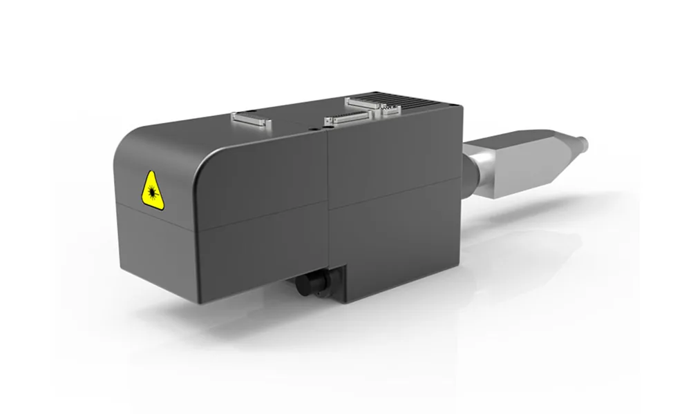
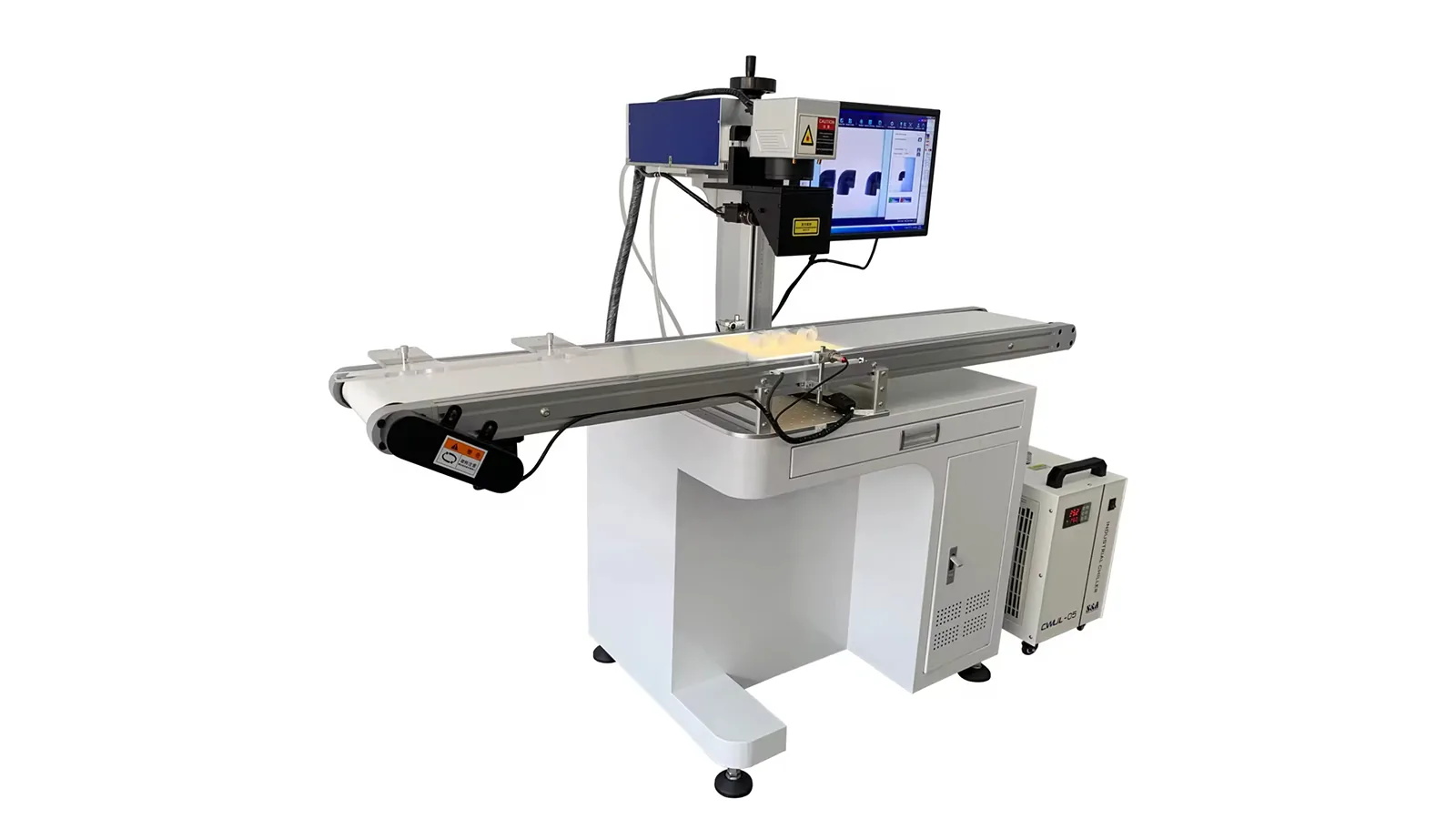
Configuration examples: These images illustrate two functions that may be retained after testing: dynamic focus for demonstrated height variation and CCD vision for demonstrated orientation or positioning control. They are equipment examples, not eyewear qualification samples.
Sample-Test Input
What Information Is Needed Before Eyewear Frame Sample Testing?
Representative frames
Supply finished frames that cover the actual material, coating, color, left-right condition, assembly state and relevant supplier/batch variation.
Marking file and zone
Provide vector artwork or controlled text, smallest characters/strokes, exact dimensions, marked side, orientation and a photo or drawing of the required location.
Target result and acceptance rule
Define readability, contrast, cosmetic limits, placement, allowable frame damage, code verification and any required cleaning, perspiration or other exposure test.
Production requirement
State batch size, variants per shift, target takt time, loading method, loose/assembled condition, inspection method and expected automation level.
From Sample to Configuration
Send the actual frame, marking requirement and production target before selecting the machine.
Representative eyewear samples make it possible to screen the laser route, verify small-character readability and cosmetic quality, test fixture repeatability, and then decide whether the final system needs standard flat-field marking, dynamic focus, vision, extraction or additional production automation.