
Metal and Plastic Pens · Small Batches · Repeatable Placement
Pen Laser Marking
Pen laser marking starts with the finished pen. The marked material and finish, usable barrel or clip area, artwork size, pen geometry, batch mix and loading method determine which laser route should be tested and whether the result can be repeated in production.
Use this guide to turn “I want to mark this pen” into a testable requirement: define the pen and mark zone, the result you need, how the part will be located, what can fail, how a representative sample should be accepted and which machine functions the test result actually justifies.
Define the job before choosing the machine
Which Pen Products and Marking Areas Are Being Evaluated?
This application covers finished promotional, gift, OEM, retail and personalized pens when the mark is placed on the barrel, cap, clip or decorative trim. Ballpoint, rollerball, fountain, stylus and similar pen formats can share the same marking task, but their construction and finish still need to be checked on the actual product.
Barrels and Caps
Metal or plastic barrels may be bare, anodized, painted, plated, lacquered, textured or otherwise coated. Define the exact marked zone rather than describing only the whole pen.
Clips and Metal Trim
Clips, bands and trim can provide a useful orientation datum, but they can also block access, reduce the available mark area or require a different fixture from the barrel.
Finished and Mixed-Material Pens
Assembled pens can combine a metal clip, plastic body, rubber grip, plating, decorative coatings, ink cartridge and springs. Test the finished construction when nearby components or cosmetic surfaces may be affected.
Why Are Pens Laser Marked?
The purpose of the mark determines what information is needed, how accurately it must be placed and what should be checked during sample qualification.
- Branding and promotional identityApply logos or brand names to corporate gifts, promotional pens and OEM products without adding a separate printed label.
- PersonalizationMark names, initials, short messages or event-specific content in small batches where artwork or text changes frequently.
- Product or batch identificationAdd model, batch, serial or order information when the pen needs controlled identification beyond decoration.
- Digital lookupUse a QR or Data Matrix code when the available area, curvature and final code size still allow reliable reading with the intended scanner.
What Information Is Usually Marked on Pens?
Mark content should be defined together with its final physical size and location. A small logo, fine name text and a machine-readable code place different demands on focus, line definition, curvature and inspection.
| Marking content | Typical use | Input required | Acceptance check |
|---|---|---|---|
| Logo or brand name | Promotional branding, OEM identity or corporate gifts | Approved vector artwork, target size, orientation and position | Shape fidelity, contrast, placement and finish consistency |
| Name, initials or short message | Personalized gifts and short-run orders | Final spelling, font, text height, order mapping and proof rule | Correct data, small-character legibility and repeatable alignment |
| Model, batch or serial identifier | Order control, inventory or traceability | Data source, format, sequence and duplicate-control method | Correct value and association with the intended pen |
| QR or Data Matrix code | Digital lookup or controlled data access | Code content, physical size, quiet area and intended reader | Readability on the actual curved surface after normal handling |
What Determines the Laser Marking Result on a Pen?
The word “pen” does not determine the process. The result comes from the interaction between the actual marked surface, the required mark, the barrel geometry, the way the pen is located and the production pattern that has to repeat the result.
| Variable | What it can change | What to define before testing |
|---|---|---|
| Material and finish | Contrast, coating response, heat sensitivity and edge quality | Known alloy/resin plus anodized, plated, painted, lacquered, soft-touch, textured or other finish |
| Mark content and feature size | Detail, readability and marking time | Logo size, smallest text/line, code size and total mark area |
| Target effect | Dark/light contrast, color change, coating removal or engraving | Define the acceptable visual and physical result, not only “permanent” |
| Barrel geometry and focus | Focus variation, distortion and usable marking arc | Diameter, taper, mark length, wrap angle, obstructions and usable zone |
| Positioning and loading | Placement repeatability, scratch risk and operator dependence | Datum, clip orientation, axial stop, contact points and loading direction |
| Batch mix and data workflow | Changeover, wrong-job risk, data errors and automation need | Batch size, variants, artwork/name changes, personalization frequency and target cycle |
What Should an Acceptable Pen Mark Achieve?
Define the acceptance target before comparing laser sources. A sample that looks good once is not enough if the final order needs small text, repeatable placement, clean coating edges or fast model changes.
- AppearanceThe required dark, light, engraved or exposed-substrate effect is clear and consistent on the intended finish.
- Fine detailSmall names, logo lines and other fine features remain legible without obvious blur, melting or ragged edges.
- PlacementThe mark stays in the agreed position relative to the clip, seam, cap, grip or other locating reference.
- Surface integrityNearby paint, plating, polished areas, grips or decorative parts do not show unacceptable discoloration, residue or fixture damage.
- ReadabilityHuman-readable text remains clear at the final size, and QR or Data Matrix codes are checked with the intended reader when used.
- Durability and repeatabilityThe mark passes the customer’s defined handling or rub requirement and repeats across representative pens from the real batch.
How Do Pen Geometry, Fixturing and Loading Affect the Process?
A pen is a narrow, often tapered workpiece with clips, seams and decorative features that define how it can be located. The setup should be based on the real usable mark zone and a repeatable datum, not only on the overall barrel length.
Barrel Diameter, Taper and Marking Arc
A short side logo on a nearly straight barrel may stay within an acceptable focus range in a fixed nest. A longer design that extends around the barrel creates more height change and may require indexed repositioning, rotary motion or another controlled-focus approach. State the required marking arc before the fixture is selected.
Clips, Seams and Decorative Features
Clips, cap seams, bands and raised decoration can reduce the markable area or create orientation errors. Use a stable datum such as the clip centerline or a repeatable cap/barrel feature, while keeping the laser path and fixture clear of protrusions.
Fixed Nest, Indexed Fixture or Rotary Motion
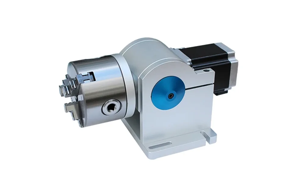
Start with the simplest handling method that can repeat the mark. A fixed nest often suits one short side mark. Manual indexing or a multi-position fixture can improve output for repeated flat-side marks. Rotary motion becomes relevant when the artwork extends beyond the usable tangent area or controlled angular positioning is required; it is not automatically necessary for every round pen.
Protect the Finished Surface
Hard fixture contact, excessive clamping or an uncontrolled loading path can scratch a finished pen even when the laser result is acceptable. Soft contact surfaces, controlled clamping and a repeatable loading sequence should be included in the sample review.
Which Laser Route Should Be Tested First?
Choose the first test from the actual marked surface and target result. The table below is a screening direction, not a universal machine selection or parameter recipe. MOPA is a fiber-source subtype, so it should be compared within the fiber route when its wider pulse-control range is relevant to the required result.
| Pen surface or task | First route to evaluate | What the sample must decide |
|---|---|---|
| Bare or exposed metal barrel, cap or clip | Start with a fiber route; include MOPA fiber in the comparison when pulse control may improve the required appearance or process window | Contrast or engraving effect, edge quality, heat/surface change, smallest detail and repeatability |
| Anodized, plated or otherwise finished metal | Begin with a fiber/MOPA comparison appropriate to the real layer and target effect rather than treating the finish as bare metal | Whether the required layer changes cleanly, whether the substrate is exposed, and whether surrounding finish remains acceptable |
| Heat-sensitive or fine-detail plastic barrel | UV is often a useful first comparison; other sources should be considered only after checking the real resin, color, additives and target effect | Contrast, line definition, melting or gloss change, surface texture and production repeatability |
| Paint, lacquer, soft-touch or decorative coating | Select the test route from the actual coating/substrate stack and whether the goal is color change, controlled removal or substrate exposure | Removal edge, residue, exposed color, coating integrity and effect on the underlying material |
| Unknown or mixed-material pen | Do not choose a source from appearance alone; separate the real marked zones and test representative finished variants | Which surface actually limits the process and whether one configuration can cover the required product mix without unacceptable compromises |
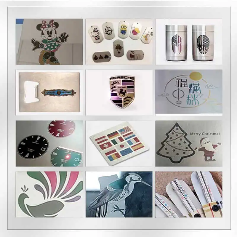
If the first route is close but unstable, isolate whether the limiting variable is the material/finish, process window, focus, fixture repeatability or incoming pen variation before adding more hardware.
What Commonly Goes Wrong When Laser Marking Pens?
A failed sample should be diagnosed by the visible symptom. Increasing laser power alone can hide the real problem when the limiting variable is the resin, coating, focus, curvature, fixture or data workflow.
| Observed problem | What to check first | What the next test should isolate |
|---|---|---|
| Weak or uneven contrast | Material/finish variation, contamination, focal height and process window | Run controlled comparisons on the same representative pen before changing multiple variables at once |
| Plastic looks melted, glossy or rough | Resin/additives, energy density, overlap, dwell and whether the selected laser route is suitable | Whether a lower-thermal-impact process window or a different laser route is required |
| Coating edge is ragged or the wrong layer is exposed | Coating thickness, target effect, energy input and focus | Whether the process can change only the intended layer without damaging adjacent finish or substrate |
| Mark shifts relative to the clip or seam | Datum choice, fixture clearance, rotational play and loading direction | Whether the error comes from the fixture or from operator presentation of the pen |
| First pen looks good but the batch drifts | Diameter/taper variation, finish variation, focus recovery and fixture repeatability | Separate incoming part variation from process-window instability |
| Small names or logo lines lose definition | Final text size, field/lens choice, focus, curvature and line density | Whether the feature is realistic at the required physical size on the real barrel |
| QR or Data Matrix looks acceptable but scans poorly | Physical code size, curvature, distortion, contrast, quiet area, reader and lighting | Test the intended reader on the finished pen rather than judging the code visually |
| Correct mark goes on the wrong pen, name or order | Job selection, variable-data mapping, variant identification, quantity tracking and part separation | Whether the error comes from data association, operator selection or changeover control |
| Pen surface is scratched during handling | Fixture contact material, clamp force, loading sequence and rejected-part handling | Redesign the contact and loading method before blaming the laser process |
How Should Small-Batch Pen Marking Move Into Production?
Small personalized orders often change names, colors, pen models or artwork more frequently than the laser recipe itself. Production therefore needs a controlled changeover and error-proofing sequence, not unnecessary automation.
Confirm the pen model/color, customer order, fixed artwork and variable-data source before loading parts.
Use the fixture, axial stop and clip/orientation datum assigned to that pen model, then recover the approved focus position.
Check names, numbering sequence, code content and order mapping before the first mark. Keep fixed artwork separate from changing data.
Check placement, spelling/data, appearance and small-detail legibility before releasing the rest of the batch.
Keep unmarked, accepted and rejected pens clearly separated so pieces are not skipped, duplicated or mixed between orders.
Reconfirm fixture insert, job file, focus/Z position, orientation and first-off approval whenever the pen model, finish or artwork changes.
How Should Representative Pen Samples Be Qualified?
A sample test should convert the target result into a reproducible process window. Use real pens from the intended production variants rather than approving one ideal coupon or one visually good piece.
- Select representative samples: include the actual pen models, colors, finishes and suppliers that may appear in production.
- Use final artwork and data: test the real logo size, smallest text, code dimensions, orientation and variable-data format.
- Compare a controlled process window: use a controlled test matrix, change variables deliberately, record each tested combination and avoid changing several unknown conditions without tracking them.
- Inspect against the defined target: check appearance, fine detail, placement, surface integrity, readability and any required rub or handling test.
- Repeat across several pens: verify that material/finish variation, barrel diameter and normal loading do not make the accepted result disappear.
- Run the real handling sequence: include loading, orientation, data selection, marking, inspection, rejection and model/artwork changeover when those steps affect production.
- Freeze the accepted condition: record the approved sample, process window, fixture/datum, focus position, artwork version and known limits that must carry into the machine configuration.
How Do Sample-Test Results Determine the Final Machine Configuration?
The final machine should be the consequence of the accepted mark and the real production method. Use the sample result to justify only the source, optics, fixture, motion, software and workstation functions that the pen application actually needs.
| Test or production finding | Configuration decision | Why it matters |
|---|---|---|
| A fiber, MOPA-fiber, UV or other tested route is the only one that reaches the accepted surface result | Laser source family and pulse-control capability | The selected source must reproduce the approved mark on the real pen material and finish |
| The mark is acceptable only inside a narrow process window or at the required batch speed | Power range, pulse/repetition capability and scan strategy appropriate to the tested route | Nominal wattage should follow the demonstrated process margin rather than be chosen first |
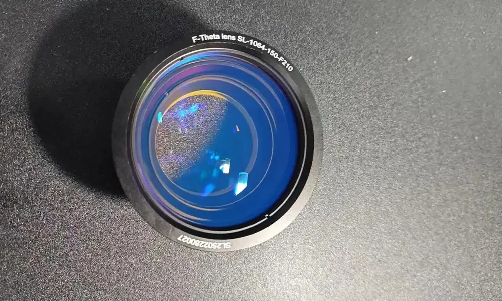
| Small names, codes or logo features require tighter detail while the mark area remains limited | Marking field, F-theta lens and optical setup | Field size and feature size must be balanced so the required detail remains readable |
| Barrel taper or height variation moves the mark outside a reliable focal range | Focus strategy, Z adjustment or controlled-focus option when justified | The optical setup must keep the required mark area inside an acceptable focus range |
| The logo extends around the barrel or needs controlled angular placement | Rotary axis, indexed motion and the related chuck/fixture arrangement | Rotary hardware is justified by the actual marking arc and positioning need, not by the fact that a pen is round |
| Mark position must repeat relative to the clip, seam or cap | Dedicated nest, locating datum, soft-contact fixture and changeable inserts | Stable part location prevents a good laser process from producing a poorly positioned mark |
| Many names, serials or short-run artwork variants are required | Software recipe structure and variable-data workflow | Correct data association and changeover control become part of the production requirement |
| Manual loading or single-piece marking cannot meet the required batch output | Multi-position fixture, indexing table or higher automation level | Automation should solve a measured handling or cycle-time limit rather than be added by default |
| Plastic or coating marking creates residue, particles or fumes | Extraction, enclosure and operator-access configuration appropriate to the actual process | A cosmetically good sample does not replace the need to configure process emissions and access safely |
| The pen length, fixture, rotary device or focusing position creates a physical fit problem | Workstation size, usable Z travel and fixture/rotary clearance | The approved process still has to fit inside the real machine work area without collisions or awkward loading |
Zhuorui Laser assembles, configures, tests and supplies complete laser marking machines. Standard machines can be matched with appropriate source, optics and workholding options, while fixture, rotary, software or higher-level automation requirements should be confirmed from the actual sample and production brief.
What Information Should You Send for Pen Marking Evaluation?
A useful recommendation requires more than “metal pen” or “plastic pen.” Send the inputs that define both the mark and the way the order will be produced:
- Actual pens, supplier/model information or clear photos of every production variant.
- Known material, coating and finish of the intended mark area.
- Mark location, available area, orientation and relationship to the clip, seam, cap or grip.
- Vector logo, final text list, numbering format or code content.
- Required mark size, smallest text/graphic feature and desired visual or physical effect.
- Barrel diameter, taper, overall pen length and any clearance limits that affect a fixture or rotary device.
- Batch quantity, number of variants, frequency of name/artwork changes and target production pace.
- Appearance, readability, rub/handling resistance and inspection method required for acceptance.
- Preferred loading method, operator expectations, destination and electrical requirements.
Discuss Your Pen Marking Requirement
Send representative pen samples, artwork, mark location, batch mix and acceptance criteria. Zhuorui Laser can use the sample result to narrow the laser route, fixture or rotary need, optical field, data workflow and workstation configuration before a standard or custom machine is confirmed.