
Energy Connector Application
Laser Marking for High-Voltage Energy Connectors, Busbars and Housings
Plan battery connector laser marking around the real assembly: conductive copper parts, insulated plastic housings, restricted functional zones, readable traceability codes and the fixture or automation needed to present every part consistently.
- High-voltage connector housings
- Copper busbars and terminals
- Mixed-material assemblies
Application Answer
Energy connector marking starts with the exact part, surface and function
A high-voltage connector can combine a molded housing, bare or plated conductors, seals, clips and fastening features. The marking task therefore has to define which component receives the code, what surface is actually being marked, which functional areas must remain unchanged, how the part is located and how the result will be qualified.
Use this page to turn a general connector-marking request into a testable application brief: part and surface, marking purpose, code content, target result, keep-out zones, geometry and loading, first-test laser direction, failure checks, production workflow, sample qualification and the machine features driven by the test result.
Part Families
Which energy connector parts are commonly marked?
Start by identifying the exact physical part that receives the mark. A high-voltage connector project may include insulated housings, conductive links, terminals, shields, covers or a completed mixed-material assembly.
High-voltage plastic housings
Molded connector bodies, protective housings and covers are common marked parts when the identification has to remain visible on the insulated exterior of the assembly.
Copper busbars and conductive links
Flat busbars, conductive links and similar current-carrying metal parts may have a dedicated marking face separate from the plastic housing.
Terminals and mixed assemblies
Plated terminals, shields, covers and completed assemblies can also be the marked object when identification is required on a specific component or on the finished connector assembly.
Why Mark
Why are energy connectors marked?
The mark should support a manufacturing or identification task on the physical connector, not exist only as a visible graphic.
Traceability through production
Part numbers, lot identifiers, serial data and supplier information can keep the physical housing, busbar or terminal associated with the correct manufacturing record as it moves through assembly and inspection.
Assembly and orientation control
Polarity marks, cavity identifiers, terminal positions and orientation symbols help distinguish similar variants and support the correct assembly or inspection step when the drawing requires visible identification.
Quality, rework and service identification
A verified code can give downstream teams a stable physical identifier for quality records, rework history or service information when the customer’s traceability system is designed around that identifier.
Marking Content
What information is usually marked on energy connectors?
The station must reproduce customer-defined content at the approved size and position, then support the required visual or scanner check.
| Content | Typical location | Engineering question |
|---|---|---|
| Part number or connector family | Plastic housing or cover | Is the mark readable across color, texture and molded draft? |
| Lot, date or supplier code | Housing, shield or busbar | How is variable data tied to the correct physical part? |
| Data Matrix or QR code | Flat housing panel or prepared metal zone | What code size, quiet zone, verification method and reader angle are required? |
| Polarity, terminal or cavity identifier | Near the relevant feature | Can the mark remain visible without entering a seal, latch or contact keep-out? |
| Logo, rating or warning symbol | Approved external face | Does the drawing define contrast, durability and inspection criteria? |
The exact content, size, location and verification method should come from the customer drawing and quality plan so the sample test reproduces the real production requirement.
Result Variables
What determines the marking result?
The connector name alone does not define the process window. Record the variables below before comparing laser sources or recipes.
- Material and surface stateFor housings, record resin grade if known, color, additives, reinforcement and texture. For conductors, record base metal, plating or coating, finish, oxidation and contamination state.
- Code and mark requirementDefine the content, minimum character or cell size, available mark area, required contrast, reader method and whether the mark is fixed or variable data.
- Geometry and optical accessCurvature, recess depth, surface angle, local height and surrounding features affect focus, field access and whether the full code can be marked without distortion.
- Datum and part presentationFixture repeatability, molded references, terminal position and variant-to-variant location drift determine whether a fixed nest is enough or feature-based positioning should be evaluated.
- Functional zones and downstream exposureKeep the process away from contacts, sealing tracks, joining areas and function-critical coatings, and define any cleaning, handling, assembly or environmental exposure the mark must survive.
- Production requirementTarget volume, takt time, loading method, variant mix, changeover frequency, verification method and reject handling affect the station even when the laser mark itself is already qualified.
Target Result
What should the finished mark achieve?
A pass result is more than a dark or visible mark. Define the acceptable result before the first sample is run so laser selection and later qualification use the same target.
- Correct content and positionThe code, symbol or identifier matches the approved artwork or variable data and lands inside the drawing-defined mark zone.
- Readable under the intended inspection conditionHuman-readable text or machine-readable code has enough contrast and geometry for the intended lighting, reader angle and inspection method.
- Acceptable surface responseThe result avoids unacceptable melting, residue, deformation, flaking, coating damage or other surface change for the specific part.
- Functional surfaces remain protectedElectrical contacts, sealing features, controlled fits, joining areas and function-critical coatings remain outside the qualified process area.
- Required downstream durabilityThe mark remains usable after the cleaning, handling, assembly or environmental exposure defined by the customer’s process or product requirement.
- Repeatability across expected variationThe process stays acceptable across representative part, surface and production variation rather than passing on one ideal sample only.
Functional Protection
Define the mark zone and keep-out zones before testing
A high-contrast code is not acceptable if it changes a functional surface or interferes with the next manufacturing step.
Candidate mark zones
- Dedicated label or code panel on the molded housing
- Non-contact metal face approved by the product drawing
- Accessible cover, shield or flange outside sealing features
- Surface that remains visible at the inspection point
Typical keep-out zones
- Electrical contacts, mating faces and conductive interfaces
- Weld, braze, crimp, solder or ultrasonic joining areas
- Seals, O-ring tracks, latch surfaces and controlled fits
- Areas where coating or plating condition is function-critical
Geometry & Handling
How do connector geometry and loading change the marking station?
Repeatable part presentation controls code position, focus and cycle consistency, while part envelope and loading access determine whether the station can handle the real production workpiece.
| Part or production condition | What must be controlled | Configuration direction |
|---|---|---|
| Flat housing panel in a tray | Repeatable datum and part seating | Standard station with manual, tray or pallet loading |
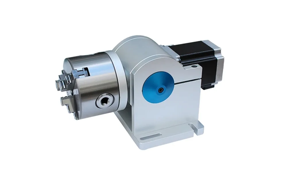
| Curved body or cylindrical terminal | Angular position and surface presentation | Rotary marking evaluation or an indexed nest |
| Variants with position drift | Feature location relative to the actual mark surface | Vision positioning evaluation when fixture repeatability alone is not enough |
| Deep recess or obstructed surface | Line of sight, working distance and focus access | Angled presentation, fixture redesign or optical-access review |
| Large or multi-level assembly | Workpiece envelope, height range, table clearance and operator/loading access | Workstation size, table, Z travel and enclosure clearance must be selected around the real assembly |
| High-mix variants and frequent changeover | Fixture, datum, recipe and data selection must return to the correct state | Quick-change tooling, recipe control and first-off verification |
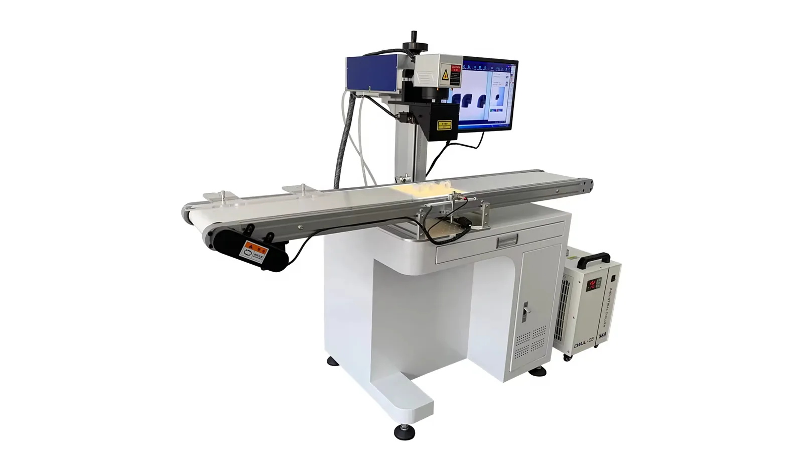
| Inline or takt-controlled production | Part arrival, stop position, cycle time and reject handling | Automatic cell or online marking after the process window is qualified |
First-Test Laser
Which laser should be tested first for each marked surface?
Do not select one laser for the whole connector by product name. Qualify the plastic housing, bare conductor and plated surface as separate marking problems whenever they differ in material or surface condition.
Plastic connector housings
UV is a practical first screening direction when heat input, edge quality or a small code on a sensitive molded surface is the main concern. Some laser-markable resins may also respond to a conditioned fiber process. Resin grade, pigment, additives, reinforcement, color and texture must be tested on the actual housing.
Bare copper and conductive busbars
Fiber or MOPA fiber is commonly evaluated first for bare conductive metal when the approved mark zone is outside functional contact or joining areas. Copper alloy, finish, oxidation, contamination, required contrast and acceptable surface change determine the usable process window.
Plated terminals and coated conductors
Identify the plating or coating before testing and define whether that layer may be altered. A process that is acceptable on bare copper cannot be assumed acceptable on tin-, nickel- or other plated surfaces. Screen the actual plated part separately and keep the test away from function-critical contact, joining and sealing areas.
If one assembly needs marks on more than one of these surfaces, qualify each surface independently first. Only then decide whether production can share a station, needs separate recipes and optics, or requires separate laser sources or stations.
Failure Modes
Where do energy connector marking trials fail, and what should be checked first?
A failed sample should narrow the next test. Separate material response, surface condition, geometry, positioning and verification problems instead of treating every failure as a power problem.
| Observed problem | Variables to isolate | Next check |
|---|---|---|
| Plastic code is too weak or uneven | Resin formulation, pigment, additives, texture, wavelength and energy density | Compare representative housings from the expected material/color range before changing the station design. |
| Housing melts, browns or deforms | Heat accumulation, pulse/scan strategy, focus and material sensitivity | Reduce thermal loading or screen a more suitable wavelength/process window; confirm edge quality and dimensional acceptability. |
| Bare metal contrast varies between parts | Finish, oxidation, contamination, alloy/surface variation and focus | Cleanly separate surface-condition variation from recipe variation, then repeat on representative lots. |
| Plating is visibly changed or damaged | Plating material/thickness, fluence and whether layer removal is permitted | Stop treating the plated surface like bare metal; define the allowed coating response and retest the actual plated component. |
| Code position drifts | Fixture datum, part seating, molding tolerance, variant geometry and vision reference | Measure the location error against the real datum and decide whether fixture control or feature-based positioning is needed. |
| Curved or recessed code distorts or drops out | Focus range, surface angle, optical access and marking field | Change part presentation, field/working distance or rotary/indexing method before increasing process energy. |
| Scanner reading is inconsistent | Code size, cell shape, contrast, glare, lighting, reader angle and position repeatability | Evaluate the code with the intended reader and lighting, then separate mark-quality issues from inspection-setup issues. |
| A functional or joining zone is affected | Mark-zone definition, fixture orientation and process spread | Move or tighten the approved mark area and requalify before production use. |
Production Workflow
What must the production marking workflow include?
A qualified sample only proves the marking direction. Production also has to keep the correct part, recipe, data, position, verification and reject decision associated through every cycle and changeover.
Confirm the connector variant, part presence, orientation and approved mark zone.
Load the validated recipe for that surface and the correct fixed or variable marking content.
Reference the fixture datum or verified feature and restore the qualified focus condition.
Run the qualified process on the approved surface without crossing keep-out zones.
Check presence, position and readability using the intended visual or scanner method.
Separate failed parts, retain the required record, and restore fixture, recipe, data mapping and first-off checks whenever the variant changes.
Projects that need PLC, MES, serial-number control or automated reader/reject logic can extend this workflow through traceability and data integration after the physical marking process is qualified.
Sample Qualification
How should representative energy connector samples be qualified?
The sample plan should reproduce the real material and surface, mark zone, code, fixture reference, post-mark exposure and inspection method. Different marked surfaces should not be merged into one test condition.
Sample test inputs
- Separate marked surfaces: test plastic housing, bare conductor and plated conductor as separate groups when their surface conditions differ.
- Exact variants: include representative resin/color or metal/plating combinations and expected lot variation.
- Drawing and restrictions: define the approved mark zone, keep-outs, datum and any function-critical surfaces.
- Production content: use the actual artwork, variable data and smallest required text or code.
- Loading and cycle: reproduce the intended fixture method, orientation, target takt and changeover conditions.
- Inspection method: use the intended reader or visual criteria, lighting and required post-mark exposure.
Qualification procedure
- Confirm the target resultCheck content, position, readability and the expected visual result against the predefined acceptance target.
- Inspect the marked surfaceLook for unacceptable residue, melting, deformation, coating change or other surface damage.
- Protect functional zonesConfirm contacts, sealing features, joining areas and controlled fits remain outside the qualified process effect.
- Run required downstream exposureApply the cleaning, handling, assembly or environmental exposure defined for the product or process.
- Apply product-specific functional checksWhere the customer drawing, quality plan or product specification requires it, complete the relevant electrical, mechanical or assembly verification after marking.
- Repeat across variation and changeoverConfirm the result can be reproduced across representative parts and after the fixture, recipe and data state is restored.
Product-level electrical or mechanical approval criteria must come from the customer’s own drawing, quality plan or product specification. The marking trial should verify against those criteria rather than inventing a universal connector threshold.
Final Machine Configuration
How do sample results determine the final machine configuration?
The machine should be configured from the process window and production conditions proven during testing, not from the connector name alone.
| What the test shows | Configuration decision | Why it matters |
|---|---|---|
| Plastic housing meets the target only with the UV route | UV source direction with optics selected for the required code size and field | The source choice follows the qualified surface response rather than a generic plastics rule. |
| Bare conductor requires a fiber/MOPA process window | Fiber or MOPA fiber source, power/pulse capability and recipe range selected from the validated process margin | The machine needs enough control to reproduce the qualified contrast without entering protected functional zones. |
| Plastic and metal surfaces need incompatible laser routes | Evaluate separate stations or an engineered multi-source architecture | One enclosure does not automatically mean one laser source can qualify every marked surface. |
| Small Data Matrix or tight mark area | Field lens, marking field, working distance and optical resolution selected around the real code | Code size and available area affect optics and usable field, not just laser power. |
| Part height changes between variants | Z travel, focus-setting method or height-control strategy sized to the qualified range | Focus has to be restored without sacrificing repeatability or loading clearance. |
| Mark position changes with part presentation | Improve the fixture or add vision positioning | Positioning method should address the measured source of drift. |
| Cylindrical or wrapped marking surface | Indexed presentation or rotary marking | The motion method must keep the qualified mark geometry and focus on the curved surface. |
| Deep recess, blocked access or large assembly | Fixture orientation, table size, workstation clearance, enclosure opening and Z/working-distance review | The actual workpiece envelope and access can become the dominant machine constraint. |
| High takt or repetitive loading becomes the bottleneck | Tray/pallet handling, conveyor integration or automatic marking cell | Automation should be added to meet the measured production requirement after mark quality is stable. |
| Variable data and reader verification are required | Scanner/vision, PLC or MES interface, data handshake and reject logic | The station must keep the physical part, code and verification result associated through the production cycle. |
FAQ
Energy connector laser marking questions
Can one machine mark both the plastic housing and the copper or plated conductor?
Sometimes, but only after the surfaces are qualified separately. If they need different laser sources, optics, focus conditions or cycle logic, the production answer may be separate stations or an engineered multi-source system rather than forcing one process onto both materials.
Is a readable Data Matrix enough to release the connector marking process?
No. The code also has to be in the approved location, the surface response must be acceptable, protected functional zones must remain unaffected, required downstream exposure must be passed, and any electrical, mechanical or assembly checks specified by the customer’s quality plan must still be satisfied.
Next Step
Send the exact connector parts, surfaces and acceptance requirements
Include the housing and conductor variants, material or plating information, drawing and keep-outs, code content and minimum size, loading method, target cycle, inspection method and any required post-mark functional checks. The sample result can then be mapped to the laser, optics, fixture, positioning, workstation and automation configuration.