
Functional Accessories & Attachments
Functional Laser Marking Accessories
Add motion, positioning, workholding, indexing, guarding or triggering around a laser marking machine. Start from the part and production constraint, then confirm the attachment size, load, travel, mounting and control interface.
- Motion & positioning
- Workholding & indexing
- Line, safety & environment
Available functional attachment families
Choose the function your marking process is missing.
Each accessory family below is paired with a relevant visual so users can identify the hardware or workstation function before reviewing travel, load, mounting, control and process compatibility.
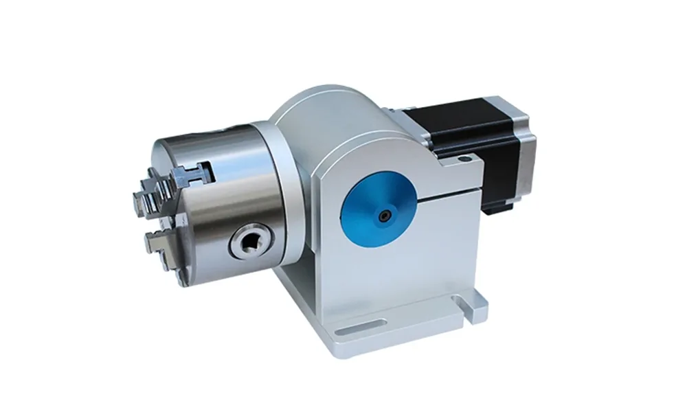
Rotary axes
Rotate rings, tubes, shafts and other cylindrical parts through a controlled angular marking path.
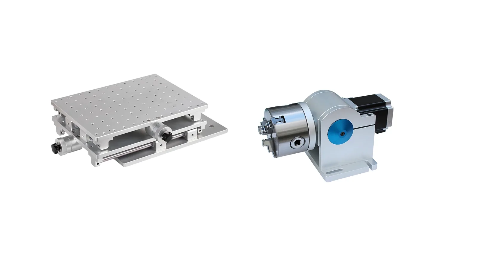
XY positioning tables
Move a workpiece or fixture through repeatable X/Y positions when one marking field is not enough.
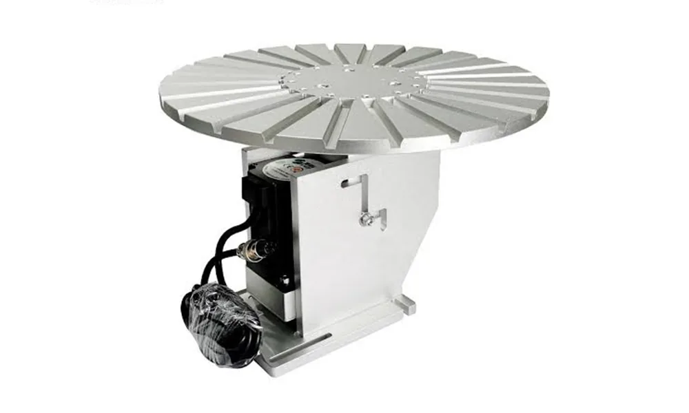
Circular rotary tables
Index multiple parts through repeated load, mark and unload positions around a circular table.
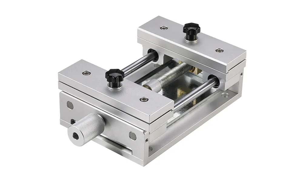
Fixtures & workholding
Create a stable datum and repeatable part orientation instead of relying on operator placement by eye.
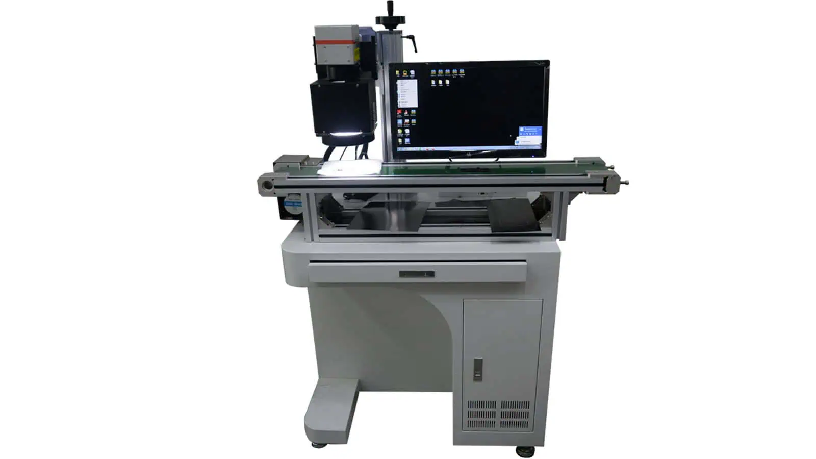
Vision positioning
Locate XY position, orientation or a visible datum when parts do not arrive in one fixed position.
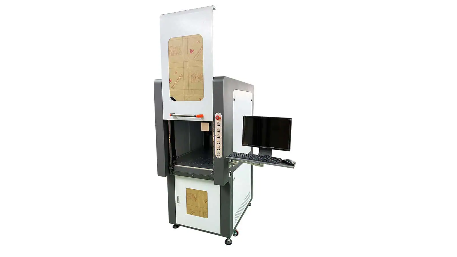
Safety & trigger devices
Add guarding, interlocks or external cycle-start signals around the marking workflow.
Selection logic
Which functional accessory should you evaluate first?
Start with the production constraint. More than one attachment may be needed, but each added function should solve a specific motion, positioning, workholding or safety/trigger problem.
Mark around a ring, tube or shaft
The mark follows a circumference or needs controlled angular access.
Evaluate → Rotary axis
Mark beyond one field
The part or fixture must move through multiple known X/Y positions.
Evaluate → XY positioning table
Part position varies in XY
Orientation or location is not repeatable enough for a fixed coordinate.
Evaluate → Vision positioning
Operator placement causes variation
The workpiece needs a repeatable datum, clamp or nest.
Evaluate → Fixture / workholding
Multiple parts cycle through one station
The process needs indexed loading, marking and unloading positions.
Evaluate → Circular rotary table
Access or triggering must be controlled
The station needs guarding, interlocks or external start signals.
Evaluate → Safety / trigger interface
Specification checklist
Confirm the fields that actually decide compatibility.
Do not select an attachment from appearance or a model name alone. Exact numbers must come from the selected accessory configuration, but the following fields define what should be checked.
Rotary axis
XY positioning table
Fixture / workholding
Vision positioning
Safety / trigger
Compatibility & integration
How does the attachment connect to the laser marking machine?
Physical fit is only one part of compatibility. The complete configuration can involve mechanical mounting, electrical power, motion control, software, I/O timing, working distance, operator access and safety functions.
Mechanical interface
- Base plate, mounting holes and available table space
- Load, center of gravity and collision clearance
- Workpiece access to the marking head and field lens
- Fixture, chuck or adapter geometry
Electrical & control interface
- Motor, driver and power requirements
- Controller or marking-software support
- PLC, sensor, encoder or trigger I/O
- Home, limit, interlock, fault and reset signals where applicable
Optical & process interface
- Working distance and focus height
- Marking field relative to part motion
- Surface geometry around the mark path
- Sample validation for the actual acceptance target
Workflow & safety interface
- Manual, indexed or continuous loading sequence
- Operator reach and maintenance access
- Guarding boundaries and service access
- Guarding and interlocks reviewed as a complete station
Common combinations
Some production problems need more than one attachment.
Combine functions only when each one solves a defined requirement in the complete marking sequence.
Rotary + fixture
Irregular cylindrical parts
The rotary provides angular motion while the fixture or jaw set establishes a stable datum.
XY table + fixture
Large or multi-position parts
The fixture establishes repeatability while the table moves through defined marking positions.
Rotary table + fixtures
Indexed multi-station loading
Fixtures hold each workpiece while the table indexes load, mark and unload positions.
Engineering confirmation
What should be confirmed before the final configuration is released?
The final accessory choice should be tied to the actual part, marking task and machine interface. A model name or product photo alone is not enough to confirm compatibility.
Request a configuration review- Part and drawingDimensions, weight, material/surface, mark position and clamping restrictions.
- Machine configurationMachine model/structure, worktable, field lens/working distance and mounting space.
- Motion and interfaceTravel, rotary/indexing behavior, motor/driver, I/O, PLC or software needs.
- Cycle and operator workflowLoading, positioning, trigger, mark, inspection, unloading and expected cycle behavior.
- Sample and acceptanceVerify the full setup with the real workpiece when motion, focus, timing or clamping affects the result.
FAQ
Questions to answer before buying or integrating a functional attachment.
Can a rotary axis be added to my existing laser marking machine?
It can often be evaluated, but fit depends on mounting, workpiece size/load, focus geometry, motor/driver and control support. Send the machine model and part details for confirmation.
How do I choose the correct rotary size?
Start from workpiece OD/ID, length, weight, clamping surface and the required angular marking path. Chuck/collet style and focus access are as important as the nominal model.
When should I use an XY table instead of a larger field lens?
Use XY motion when the part must move through multiple known locations. A larger field lens changes the optical field and can introduce different trade-offs, so the two options solve different constraints.
Does vision positioning replace a fixture?
Not always. Vision can locate position and orientation, while a fixture may still be required to control height, tilt, movement during marking or repeatable loading.
Can several functional accessories be combined?
Yes. Common combinations include rotary + custom jaws, XY + fixture, or rotary table + dedicated fixtures. The combined mechanical, optical and control interfaces should be reviewed as one station.
Do you provide drawings or interface information?
For a configuration review, request the available dimension, mounting and interface information for the selected accessory. Final drawings and wiring details should match the actual configuration.
What should I send for an accessory recommendation?
Send the part or drawing, material/surface, mark artwork/location, part size/weight, machine model, positioning or motion problem, target cycle, available I/O and any guarding or access constraints.
Next step
Send the part, machine model and production constraint for a functional-accessory configuration review.
We can narrow the attachment family, required size/travel/load, mounting and control interface, then confirm what still needs a sample, drawing or engineering check before final configuration.
Start an OEM & custom inquiry