
Glass Laser Marking for External Marks and Sample Validation
Glass can be laser marked on its external surface, but the usable process depends on glass type, coating, wall thickness, focus stability, desired contrast and fracture risk. This page helps process engineers evaluate UV, CO2 and selected green laser directions for surface marks only. Zhuorui Laser does not offer or target crystal subsurface engraving equipment.
Can glass be laser marked without turning this into a subsurface engraving project?
Yes, many glass parts can receive external surface marks, but the process should be treated as a material and sample validation problem, not as a one-size machine purchase.
For glass surface marking, the practical target is usually a frosted or matte mark, a coating-removal mark, a small logo, an alphanumeric code or a machine-readable code that remains legible under the intended lighting. The best first laser direction depends on whether the laser must interact with the glass itself, a coating on top of the glass or a mark-enhancing layer.
UV laser marking is often reviewed first for fine external marks on glass because it can localize energy more tightly than many longer-wavelength approaches. CO2 laser marking may be suitable for surface frosting, decorative marks or some packaging and glassware tasks. Green laser marking can be reviewed only where a standardized green-laser configuration and sample result are confirmed. Standard 1064 nm fiber marking should not be assumed to work on clear uncoated glass.
Glass type, surface state and coating decide the process window
The word glass is too broad for a reliable machine recommendation. A sample made from the same glass family, thickness and coating stack should be reviewed before final configuration.
Glass composition and surface condition change the marking response
Common container glass, flat glass, colored glass and general coated glass can respond differently because composition, surface finish, thickness and coating affect how the laser interacts with the part. Use a sample that matches the actual production glass instead of assuming one setting will transfer across different ordinary glass products.
Coated glass may mark through the coating first
Painted, mirrored, coated or printed glass may be marked by controlled coating removal rather than by directly modifying the glass body. The coating stack, adhesion and required contrast become part of the test, not an afterthought.
Shape, wall thickness and mark position can change the machine setup
Flat glass is usually easier to keep in one focal plane. Bottles, tubes and cylindrical parts may need a rotary or custom fixture, while large curved or height-varying surfaces may require a smaller marking field or controlled height strategy. Thin-wall glass and marks close to edges, holes, seams or formed features need more conservative testing because local damage can have a greater effect on part strength. For large parts with a small marking area, machine size should also be based on loading, fixture clearance and mark position—not only the overall part dimensions.
Common glass parts—and why they are marked
The application context matters because the part form, mark purpose and inspection method determine what should be tested on the real glass.
| Glass part | Why it may need marking |
|---|---|
| Bottles and containers | Batch, date, product identification, branding or traceability information. |
| Flat glass plates and panels | Symbols, identification, simple graphics, reference marks or coating-removal features. |
| Coated, painted or printed glass parts | Selective coating removal, contrast graphics, labels or identification marks. |
| General consumer glass products | Logos, simple identification, personalization or decorative surface marks. |
| Decorative and consumer glassware | Logos, personalization, decorative graphics or frosted surface effects. |
Which laser should be evaluated first for glass surface marking?
Start from the target effect and surface condition, then select the laser family. Average power alone does not define success on glass.
| Laser direction | Where it may fit | Main risk or boundary | Validation needed |
|---|---|---|---|
| UV laser marking | Fine logos, small text, code marks and lower heat input trials on selected glass and coatings. | Still can create microdamage if focus, energy density or scanning strategy is wrong. | Contrast, edge quality, microcracks, code readability and usable cycle time. |
| CO2 laser marking | Frosted surface effect, decorative marking, some bottle or glassware surface tasks. | Surface microcracking or roughness may be part of the mark, so strength impact must be reviewed. | Frost uniformity, chipping, tactile roughness, edge distance and part rejection definition. |
| Green laser marking | Special projects where the actual source, optical setup and sample result are confirmed. | Do not assume a green system is available or optimal for every glass project. | Confirmed machine configuration, contrast and thermal effect on the submitted sample. |
| Standard fiber laser | May help where the target is a coating, metalized layer or mark-enhancing surface, not clear glass itself. | Clear uncoated glass is not a default fiber-laser material. | Coating response, adhesion after marking and visible contrast under use lighting. |
- Clear, uncoated glass + fine external mark: UV is often a useful first trial, subject to the actual glass and acceptance limits.
- Frosted or matte surface effect: CO2 is often worth evaluating first, with close inspection for roughness, chipping and microcracking.
- Painted, coated, mirrored or printed glass: first identify whether the target is the coating or the glass substrate, then test the wavelength against that surface stack.
- Metalized or laser-responsive surface layer: fiber may be considered for the layer rather than assumed to mark clear glass directly.
- Unusual glass, tight cosmetic limits or special optical requirements: compare sample results before locking the machine family.
Fracture risk, focus and contrast must be tested together
A readable mark is not enough if the glass chips, cracks, weakens, fails handling or cannot be verified under production lighting.
Fracture and edge distance
Thin-wall glass, sharp edges, holes, seams and high local energy density can increase chipping or cracking risk. Testing should reproduce the real mark position, edge distance and part geometry rather than relying on a flat reference coupon alone.
Focus and field size
The useful field is not only the printed marking area. Larger fields can reduce spot quality at the edges. Curved or height-varying glass may need a fixture, rotary, smaller field or focus-check workflow. For focus setup details, use the laser focus guide.
Contrast and readability
Transparent glass can make contrast depend on background, lighting angle and viewer position. DataMatrix or QR marks should be checked with the actual reader, lighting and viewing angle. If a DPM quality grade is required, use a verifier and agreed method, module size, quiet zone and acceptance rule; a scanner read alone is not a quality certification.
What should be tested before choosing the machine?
The sample test should define what is acceptable, not just whether the laser can leave a visible mark.
Confirm the material
Send the glass type, thickness, color or tint, coating and any cleaning or post-process requirement.
Define the target mark
Provide artwork, code size, line width, contrast target, position tolerance and whether the mark can be tactile.
Check damage limits
Review chipping, microcracks, coating lift, edge damage, optical distortion and acceptable scrap definition.
Translate to production
Estimate loading, positioning, marking, verification, unloading and data handling instead of using laser scan time alone.
Do not approve a process only because the mark is visible. Re-test the laser route, focus, scan strategy or fixture if you see visible cracking or edge chipping, excessive microcracking under the agreed inspection method, coating lift or irregular removal, inconsistent appearance across curvature or part batches, unreliable code reads under normal production lighting, or an acceptable result that requires an impractical cycle time.
Final acceptance should cover five points: appearance, damage limits, readability, repeatability and total production cycle time.
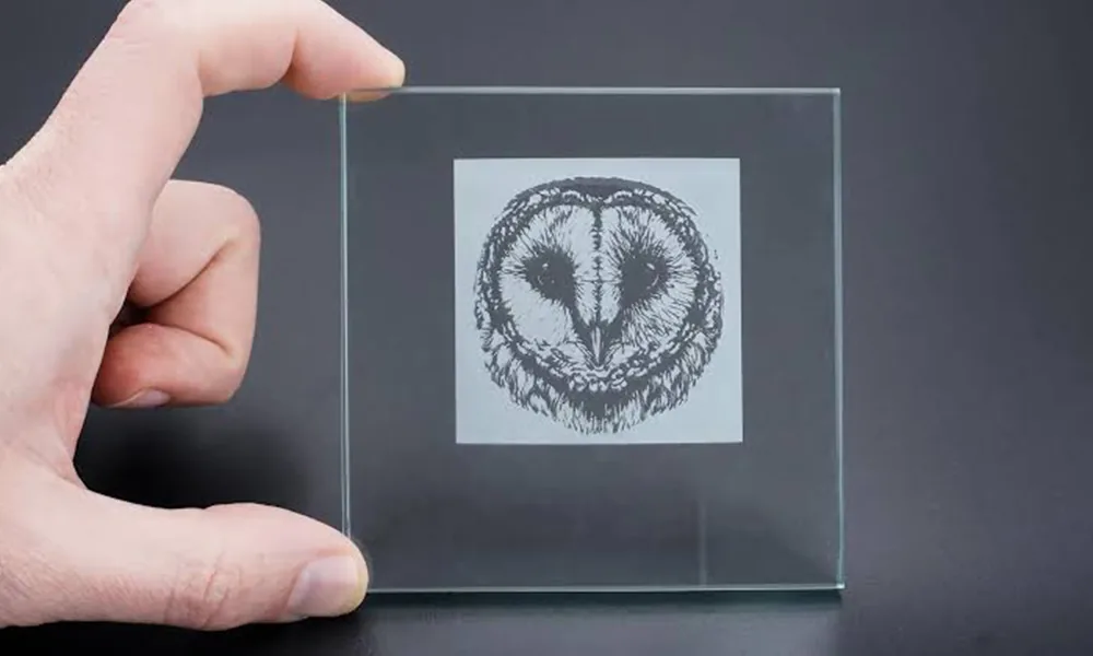
Machine setup follows the glass sample, marking target and production method
Zhuorui Laser configures complete laser marking machines by matching laser source, optics, fixture, enclosure, software and workflow needs. Product pages own detailed machine specifications; this material page explains the configuration questions.
Desktop or enclosed workstation
For small batches, samples and many offline parts, a desktop or enclosed workstation may be enough. Industrial UV, CO2, green and 1064 nm systems can involve invisible or reflected radiation, so guarded beam paths, interlocked enclosures, emergency stop, service eyewear rules and local extraction for laser-generated airborne contaminants should be evaluated as a complete system.
Fixture, rotary or positioning aid
Bottles, tubes and curved glass may need a rotary or custom fixture. Repeated location matters for small codes, logos near edges and multi-side marking.
Vision, flying or automation review
Inline marking, variable data, barcode verification or moving products require project information: part spacing, line speed, trigger signal, data source, reject logic and safety layout. Line integration is not automatically flying marking; moving-part marking needs separate validation of encoder control, focus stability, mark quality and guarding.
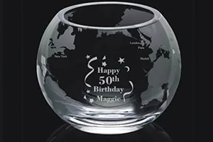
Use the actual glass part to lock the machine setup
The visual appearance of a glass part is only a starting point. Before quotation, the sample should be matched to the intended mark, its position on the part and the production method.
What this page does not offer
This page covers external glass surface marking and surface-condition review. It does not offer crystal subsurface engraving, 3D inner-glass portrait machines, anti-counterfeit inner marks or ultrafast internal glass modification systems. Those topics can require different equipment, proof standards and safety review, and they are outside Zhuorui Laser’s current product scope for this page.
For process terminology, see the resource page on laser marking vs engraving vs etching. For verified sample evidence when available, use the material sample gallery.
Glass surface laser marking questions
Can a laser make a black mark on clear glass?
Not as a universal promise. Some processes create a frosted or white matte mark; some coated glass can show dark contrast after coating removal or coating reaction. If a dark mark is required, the exact glass, coating and viewing conditions must be tested.
Is UV always safer for glass than CO2?
No single laser is automatically safe for every glass part. UV is often reviewed for fine marks and lower localized heat input, while CO2 may fit frosted surface effects. Both can damage glass if focus, energy density, scan strategy or fixture setup is wrong.
Does this guide cover every type of glass?
No. This guide focuses on general external surface marking on ordinary glass. Glass with specialized composition, strengthening treatment or application-specific performance requirements should be evaluated under the dedicated material route for that glass family.
Do you provide crystal subsurface engraving machines?
No. This page does not offer or target crystal subsurface engraving equipment. Zhuorui Laser can review external surface marking on glass samples and recommend a suitable marking-machine direction when the material, mark target and production requirements are clear.
What information should I send for a glass marking quote?
Send the glass type, thickness, coating, part photos or drawings, mark file, mark size, target contrast, production quantity, cycle-time target, fixture or automation needs, destination voltage and sample quantity. This helps narrow the laser source, optics, enclosure and testing plan.
Send your glass sample details before choosing a machine
A practical recommendation needs your glass type, surface condition, target mark, part geometry and production method. Zhuorui Laser can review the application and recommend a realistic machine configuration for testing and quotation.