
Borosilicate Glass Marking
Borosilicate glass can be laser marked, but the useful process depends on the exact grade, wall thickness, surface stack, part geometry and required result. Low thermal expansion does not eliminate localized laser damage, so the final route should be chosen from the real part and an agreed acceptance test rather than from a generic glass recipe.
Can borosilicate glass be laser marked?
Yes, selected borosilicate parts can receive external laser marks. The practical question is which interaction creates the required surface effect without unacceptable cracking, chipping, haze or loss of readability.
For fine logos, small text and traceability codes on clear, uncoated borosilicate, UV is often a sensible first route to evaluate because it can localize energy at the surface. CO2 can be evaluated for controlled frosted or matte effects. Green routes are project-specific. A standard 1064 nm fiber or MOPA source should not be assumed to mark clear, uncoated borosilicate directly; it becomes more relevant when a coating, printed layer, pigment, film or metalized surface is the actual target.
“Thermal-shock resistant” does not mean “immune to laser damage.” The useful result is the one that passes the final inspection, cleaning and service conditions on the real part.
What makes borosilicate different for laser marking?
Borosilicate is a material family, not a single optical or thermal recipe. The value of a separate borosilicate test is that grade, low-expansion behavior, wall geometry and surface stack can change both the marking window and the failure mode.
Do not treat every borosilicate part as 3.3
Low-expansion 3.3 borosilicate is common in technical glass, but specialty optical, amber, colored, doped and application-specific formulations can respond differently. Confirm the actual supplier grade instead of inferring it from the product type.
Low bulk expansion does not remove local crack risk
The laser creates a fast, localized energy gradient. Spot size, pulse condition, overlap, scan speed, pass count and cooling time can still produce whitening, chipping or microcracks even when the glass has good bulk thermal-shock resistance.
The glass may not be the layer being marked
Ceramic print, enamel, paint, film, adhesive, anti-reflection coating or metalized layers can absorb the wavelength differently from bare borosilicate. In those cases, the process may be controlled layer modification or removal rather than direct glass marking.
Polished, molded and contaminated surfaces do not compare directly
Surface roughness, mold release, oil, salts and cleaning residue can change contrast and scatter. Test the sample in the intended pre-mark condition and inspect it again after the real cleaning cycle.
Tell us what happens before and after marking
Forming, annealing, coating, washing, heating and chemical exposure can change the final appearance or reveal damage that is not obvious immediately after marking. These steps are test inputs rather than a universal before/after heat-treatment rule.
Clear marks depend on background and lighting
A mark that looks acceptable on a dark bench may look weak in transmitted light or on the final assembly. Define viewing angle, illumination, reader and contrast expectation before approving the process.
Where borosilicate is used—and why those parts are marked
The product context matters because it changes wall geometry, cleaning, heat exposure, optical constraints and the reason for the mark. The examples below stay at the material-decision level rather than expanding into line integration or industry compliance.
Laboratory glassware
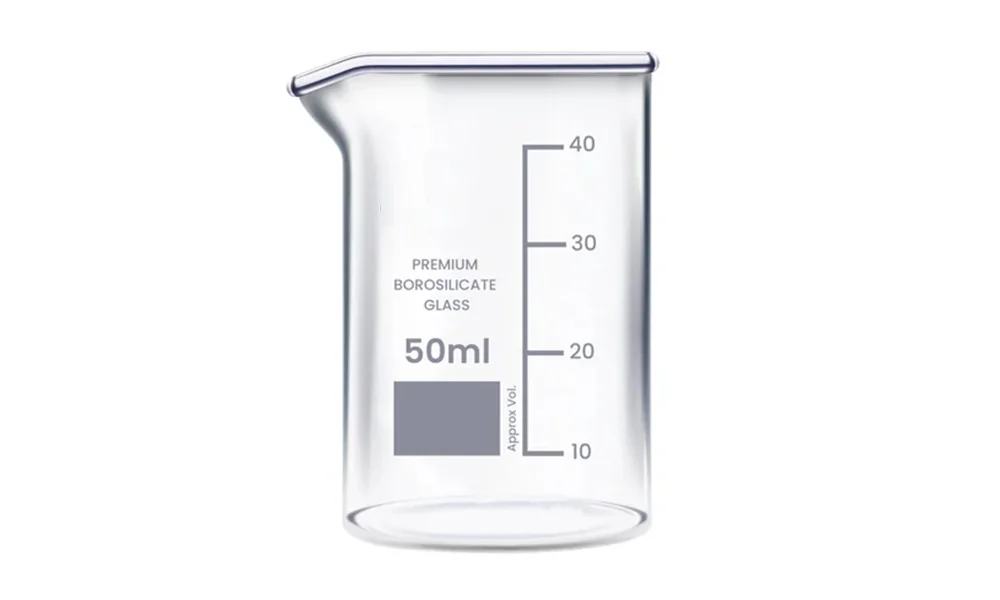
Beakers, tubes, flasks and measuring parts may need logos, volume information or traceability. Thin walls, cleaning and repeated handling make mark quality more important than first-look contrast alone.
Vials and ampoules
Curved thin-wall parts may need identification or production traceability. The laser test should focus on wall condition, fixture pressure, mark size, cleaning and readability without assuming every vial uses the same borosilicate grade.
Process sight windows
Part numbers, service IDs or orientation marks may be placed outside the functional viewing area. Thickness, edge distance, sealing surfaces and optical appearance become important acceptance inputs.
Lighting and lamp tubes
Branding or manufacturing IDs may be needed on curved glass. Diameter, tube length, support method and later heat exposure can change focus stability and fixture design.
Scientific and optical components
Identification may need to remain outside a functional aperture or preserve a specified surface condition. Mark position and optical acceptance should be defined before the laser test.
Thermal products and cookware
Branding or traceability marks may need to survive repeated heating and cleaning. A visually attractive mark should still be checked after the intended thermal and chemical exposure.
What is usually marked on borosilicate glass?
The content of the mark determines feature size, contrast demand, code-reading method and how much process variation can be tolerated.
Codes, serials and part information
- Serial numbers, lot or batch IDs
- Part numbers and service identifiers
- QR or DataMatrix codes
- Manufacturing or inspection identifiers
Scales, logos and controlled surface effects
- Logos and brand marks
- Graduation or scale information where appropriate
- Orientation or service marks
- Decorative patterns or coating-removal contrast marks
Why the mark content changes machine selection
A large simple logo can tolerate a different field, spot condition and verification method than a small machine-readable code. Send the artwork, final mark size, smallest feature and required reading distance or verifier method with the sample.
Define the result before choosing the laser route
“Can it be marked?” is too broad for borosilicate. The useful process is the one that creates the required visual or functional result and still passes the material acceptance checks.
Fine visible mark
PrioritySharp text or logo with controlled surrounding change.
CheckEdge definition, contrast, haze, microcracks and repeatability.
Frosted or matte mark
PriorityVisible surface contrast or controlled texture.
CheckUniformity, roughness, whitening, chipping, haze and later heat exposure.
QR / DataMatrix
PriorityMachine readability on the real transparent background.
CheckModule definition, lighting, reader/verifier result and stability after cleaning.
Coating or print removal
PriorityContrast created by selectively modifying the surface layer.
CheckRemoval completeness, exposed-glass condition, edge adhesion, debris and fumes.
Decorative surface mark
PriorityConsistent appearance over the required area.
CheckVisual uniformity, handling, cleaning and any later heat exposure.
How wall thickness, curvature, size and mark position change the test
A flat coupon can hide the focus drift, reflections, support pressure and working-envelope limits that appear on the real borosilicate part. Geometry should therefore be treated as a machine-selection input, not just a fixturing detail.
| Part condition | What changes in the laser test | Machine or fixture consequence |
|---|---|---|
| Small thin-wall tube or vial | Limited wall thickness, curvature and sensitivity to point pressure make focus and support more critical. | Soft support, rotary accuracy, low runout and controlled clamping may matter more than nominal source power. |
| Large-diameter or long tube | Part runout and focus variation can change across the mark path. | Review rotary capacity, secondary support, work envelope, loading access and whether height compensation is needed. |
| Thick window or block | Back-surface reflections, transmitted energy and optical-zone restrictions can become more important. | Review focus position, beam termination, fixture material and permitted mark area. |
| Mark near a rim, hole or formed transition | Edge distance and local geometry can increase chipping or crack sensitivity. | Fixture location, mark offset and reject criteria should be tested on the real feature, not a flat spare coupon. |
| Large mark or wide marking field | Spot condition and focus can vary across the field while cycle time increases. | Lens / field selection, part repositioning, multi-position fixtures or a larger motion strategy may need review. |
Which laser route should be tested first?
Choose the first test from the borosilicate condition and the required mark effect. This keeps the decision specific to the actual grade, surface layer, wall geometry and acceptance criteria.
Useful starting direction for localized external marks, small text and compact codes.
Evaluate when controlled frosting or surface texture is acceptable.
The responsive coating, print, film or metalized layer can change the suitable wavelength.
Green or another route should follow the exact source, optics and real-sample response.
| Actual condition | First route to evaluate | Why this route is screened | Do not approve until |
|---|---|---|---|
| Clear, uncoated part needing fine text, logo or small code | UV first | Useful starting direction when a localized external mark and small features are required. | Contrast, haze, microcracks, code reading, focus tolerance and cycle time pass on the real part. |
| Clear, uncoated part where a frosted or matte surface effect is acceptable | CO2 comparison | Can create a stronger surface-texture effect when controlled thermal interaction is acceptable. | Whitening, roughness, chipping, thermal exposure and optical appearance remain within the agreed limits. |
| Printed, enamelled, pigmented, filmed or metalized borosilicate | Test the responsive surface layer | The layer may absorb differently from the underlying glass; 1064 nm fiber / MOPA can become relevant for some responsive layers. | The layer change, exposed glass, adhesion, debris, fumes and final appearance are acceptable. |
| Special grade or absorption requirement not resolved by the first routes | Green or another confirmed route by project review | Only after the exact source, optics and material condition are known. | A real sample shows a repeatable advantage over simpler routes without adding unacceptable material risk. |
A higher nominal power does not automatically create a better borosilicate result. Source wavelength, pulse behavior, spot condition, overlap, field size, focus and the real part geometry determine the usable process window.
A visible mark can still be an unacceptable borosilicate result
A mark is acceptable only when it meets the required appearance or readability without creating unacceptable damage or use-related problems.
Microcracks and edge chipping
Inspect at normal and magnified scale, especially on thin walls and marks close to rims, holes, ground edges or formed transitions. A visually clean mark can still contain a damaging crack network.
Haze, whitening and roughness
Frosting can be intentional, but uncontrolled haze or roughness may interfere with optical appearance, cleaning or the agreed cosmetic standard.
Cleaning and chemical exposure
Check for residue trapping, loss of cleanability or degradation after the intended detergents, solvents or process fluids.
Thermal exposure after marking
If the part later sees heating or hot/cold cycling, include that exposure in validation. Low expansion does not guarantee that a laser-marked area will remain damage-free.
Fixture and focus sensitivity
Thin tubes and curved parts can fail because of clamp pressure, rotary runout or focus drift even when the laser parameters look acceptable on a flat coupon.
Transmission and back-surface paths
Clear borosilicate may transmit part of the incident beam at some wavelengths. Review internal and back-surface reflections, fixture reflectivity and beam termination for the exact source and optical setup.
Qualify enclosure, interlocks, beam termination and extraction for the selected process; product-specific compliance remains a separate responsibility.
Validate the result on the real borosilicate part
Use the finished or representative part whenever possible, because curvature, wall thickness, surface layers and process history can change the result.
Identify the material
Share supplier grade or datasheet, color, wall thickness, surface finish and any later forming, annealing, coating, heating or cleaning step.
Map the geometry
Provide diameter, length, height, curvature, rims, holes, mark position, edge distance and the available support or loading method.
Define the mark
Send the artwork, mark size, smallest feature, target effect, code type and the final viewing or reading condition.
Set the pass/fail rule
Define the required appearance or code reading, damage limits, any cleaning or durability exposure, quantity and complete cycle-time target.
What the sample review should return
- Documented result on the submitted borosilicate part
- Source routes compared, including rejected directions
- Observed defects and pass/fail inspection outcome
- Provisional process range, focus sensitivity and machine direction
- Open risks that still require customer validation
No Zhuorui borosilicate result is presented as verified sample evidence until the material, test condition and result are documented.
When should you re-test?
Re-test when a change can alter absorption, heat flow, focus, support or the acceptance target. Typical triggers include:
- glass supplier, grade, color or formulation
- wall thickness, tube diameter or part geometry
- coating, print, surface finish or cleaning method
- mark position, edge distance, artwork or code size
- forming, annealing, heating or chemical exposure
- laser source, lens, fixture or production method
The approved condition is the material + geometry + surface + process combination, not the word “borosilicate.”
Turn the sample result into a machine configuration and quote
Machine selection should follow the verified sample window. The test result determines the source direction first, then the optics, fixture, work envelope, safety system and production method needed to reproduce it.
Laser source
Select the route that produced the required mark with an acceptable damage margin: UV, CO2, a confirmed special route, or a wavelength matched to a responsive surface layer.
Optics and field
Use mark size, smallest feature, focus tolerance and required field to choose the lens / working-field direction instead of selecting a field only from the largest artwork dimension.
Fixture and focus control
Choose flat support, rotary, soft support, custom fixture or height-control needs from the real diameter, wall thickness, runout and permitted contact points.
Work envelope
Confirm part length, diameter, height, loading clearance, mark location and whether the part must be repositioned or supported at more than one point.
Safety and extraction
Configure enclosure, interlocks, viewing, beam termination and extraction around the selected wavelength, transmitted/reflected paths and any coating-generated fumes.
Production mode
Decide whether the job is manual, batch, rotary, vision-assisted or an inline project review based on loading, variable data, position tolerance and inspection needs.
Throughput target
Provide target parts per hour or complete cycle time, including loading, positioning, marking, code verification and unloading. Scan speed alone is not the production cycle.
Quotation package
Send the confirmed material, drawing, mark file, acceptance criteria, quantity, cycle target, fixture needs and automation scope so the machine recommendation is tied to the tested condition.
Choose the right glass marking guide for the actual material condition
This guide focuses on external surface marking of borosilicate glass and on the material variables that change its test route. For broader glass-surface behavior, use the general glass laser marking guide. If the part is thermally tempered or the main question is whether to mark before or after tempering, use the tempered glass marking guide.
Internal 3D crystal engraving, subsurface portrait equipment and ultrafast internal modification are different process scopes. For terminology, see laser marking vs engraving vs etching.
Borosilicate glass laser marking FAQs
Does a standard fiber laser mark clear borosilicate glass?
Do not assume it will. A 1064 nm fiber or MOPA source is more relevant when a responsive coating, pigment, film or metalized layer is the actual target; clear uncoated borosilicate needs a different first-test route.
Is UV always the safest laser for borosilicate?
No. UV is often a useful first direction for fine external marks, but it is not automatically crack-free or suitable. Focus, pulse conditions, wall thickness, edge distance, mark size and the required contrast still need validation.
Can CO2 make a frosted mark on borosilicate?
CO2 can be evaluated for selected frosted or matte effects, provided the surface quality and damage level remain acceptable for the intended use.
Does borosilicate thermal-shock resistance prevent laser cracks?
No. Low expansion improves bulk thermal behavior, but the laser still creates a localized gradient that can produce microdamage.
Do I need to re-test if the glass supplier or wall thickness changes?
Yes. Re-test when the glass grade or supplier, geometry, surface stack, process history, mark position, laser source, lens or fixture changes in a way that could alter the result.
What information should I send for a quote?
Send the grade or datasheet, part drawing or photos, wall thickness, diameter or overall dimensions, coating or print information, mark file and size, mark position, required result, inspection method, cleaning or durability requirement, target parts per hour or complete cycle time, fixture needs and automation scope.
Send the real borosilicate condition before choosing the machine
Include the supplier grade or datasheet, wall thickness, part dimensions, surface stack, artwork, mark position, target result, cleaning or thermal exposure, inspection method and target parts per hour. Zhuorui Laser can use those inputs to screen the laser route, fixture and machine configuration for sample testing and quotation.