
Material feasibility and risk guide
Laser Marking on Fiberglass Composites
Fiberglass is a layered composite, not a single laser response. Resin chemistry, glass reinforcement, gel coat or paint, surface color and laminate schedule determine whether a mark develops useful contrast or exposes fibers, creates dust and leaves heat damage.
Quick answer
Can Fiberglass Composite Be Laser Marked?
Often it can be screened, but the acceptable result belongs to the exact finished laminate. A beam may change the resin while leaving glass strands visible, or it may create contrast on a gel coat without reaching the reinforcement. The same trade name can therefore produce different contrast, texture, dust and heat-affected results.
Start with the final part, not a generic “fiberglass” label. Record resin family, glass percentage or fabric, gel coat/paint, color, thickness, cure state and target mark. Then compare source and parameters on representative pieces before choosing a production machine.
Material construction
What Determines Laser Marking Results on Fiberglass?
The result is governed by the resin matrix, glass reinforcement and whatever surface layer the laser actually reaches. Identify these variables before comparing laser routes, because different laminate constructions can produce very different contrast, debris and damage at the same apparent surface color.
Resin Matrix
Polyester, epoxy, vinyl ester and filled systems can darken, lighten, ablate, char or leave residue differently. Cure, pigment and filler loading shift the process window.
Glass Reinforcement
Woven fabric, chopped strand mat and roving create different surface texture and fiber orientation. Resin removal can expose strands before a readable mark is achieved.
Review fiber risksGel Coat, Paint or Skin
A pigmented or coated surface may carry the contrast, but adhesion, thickness, cure and downstream cleaning decide whether the mark remains acceptable.
Review target resultTypical products and marking reasons
Where Are Fiberglass Parts Used and Why Are They Marked?
Fiberglass-reinforced parts are used where low weight, corrosion resistance, electrical insulation or molded composite construction is useful. The marking requirement usually comes from identification, traceability, assembly control, inspection or maintenance rather than from the material itself.
Electrical and industrial housings
Enclosures, covers and molded housings
- Part identification and revision control.
- Serial or batch traceability.
- Warning, service or inspection identification.
- Durable labels where adhesive labels are undesirable or difficult to maintain.
Panels and structural composite parts
FRP panels, covers, profiles and molded structures
- Assembly position or matched-part identification.
- Manufacturing lot and process tracking.
- Maintenance, inspection or replacement reference.
- Branding or permanent product identification when the finish allows it.
Mark content
What Is Usually Marked on Fiberglass Parts?
The content should be defined before testing because feature size, code density, required readability and mark area can change the process window and machine configuration.
| Mark content | Typical purpose | What to confirm during testing |
|---|---|---|
| Part number / model | Permanent product or component identification. | Character clarity, line width, edge quality and contrast on the final finish. |
| Serial number / batch or lot code | Traceability through production, inspection, service or replacement. | Repeatability across representative batches, colors and surface conditions. |
| QR / Data Matrix / machine-readable code | Link the physical part to digital records or work instructions. | Code size, cell definition, quiet zone, scanner performance and durability after cleaning or handling. |
| Logo / text / warning or service identification | Branding, orientation, maintenance or safety-related identification where appropriate. | Appearance, readability, protected zones and whether any fiber exposure or surface change is acceptable. |
Acceptance target
What Marking Result Should You Target?
A good fiberglass mark is not simply the darkest mark. The target should combine readable identification with controlled surface change, intact reinforcement, acceptable debris, clean edges and the durability or functional checks required by the finished part.
Readable Contrast
Characters or codes should remain legible under the intended viewing, scanning and lighting conditions. Gloss, pigment and surface texture can change apparent contrast.
Controlled Surface Change
The laser should create only the surface modification needed for the mark. Excess resin recession or deep texture change is not a benefit if it exposes reinforcement or weakens the finish.
Intact Reinforcement
Where the application requires an undisturbed laminate, glass strands should remain covered and secure rather than visible, loose or frayed.
Clean Edges and Low Loose Debris
Define how much halo, residue, loose fiber or redeposited dust is acceptable after the specified extraction and cleaning process.
Required Durability
Acceptance may include abrasion, handling, cleaning, UV exposure or chemical-contact checks when those conditions matter in service.
Finished-Part Function
For functional composite parts, the mark must not compromise critical requirements such as surface integrity, insulation, sealing, bonding or another application-specific function.
Part geometry
How Do Part Shape, Thickness and Size Change the Process?
Geometry does not change the resin chemistry, but it changes focus control, heat sensitivity, fixture design, field coverage and how representative a sample really is. Test the area and part form that will be marked in production.
Flat Small Parts
Flat, rigid parts are easier to hold within the focal range and marking field. Even here, surface gloss, local resin richness and molding texture can move the acceptable window.
Curved or Contoured Parts
Curvature changes working distance across the mark. A narrow curved zone may be handled with fixture orientation or rotary motion; larger height variation can require multi-position or 3D focus control.
Large Panels and Long Profiles
The mark may be small while the workpiece is large. Field size, workpiece access, support, panel flatness, repositioning and motion strategy can become more important than nominal laser power.
Thin Walls, Edges and Functional Zones
Thin sections, edges, bonded regions, sealing surfaces and other functional zones may tolerate less heat or surface removal. Qualification should include the real production location, not only a thick central coupon.
First-test route
Which Laser Route Should Be Tested First?
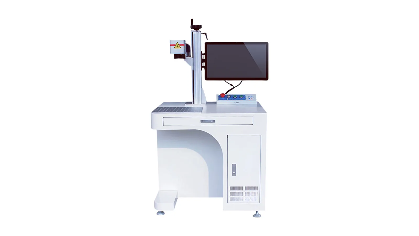
Choose the first test from the layer the beam actually sees and the result you need. The table sets a starting order, not a universal machine recommendation; the exact resin, finish, pigment, filler, thickness and acceptance target still need representative samples.
| Finished-surface condition | Route to screen first | Why it enters first | What can change the decision |
|---|---|---|---|
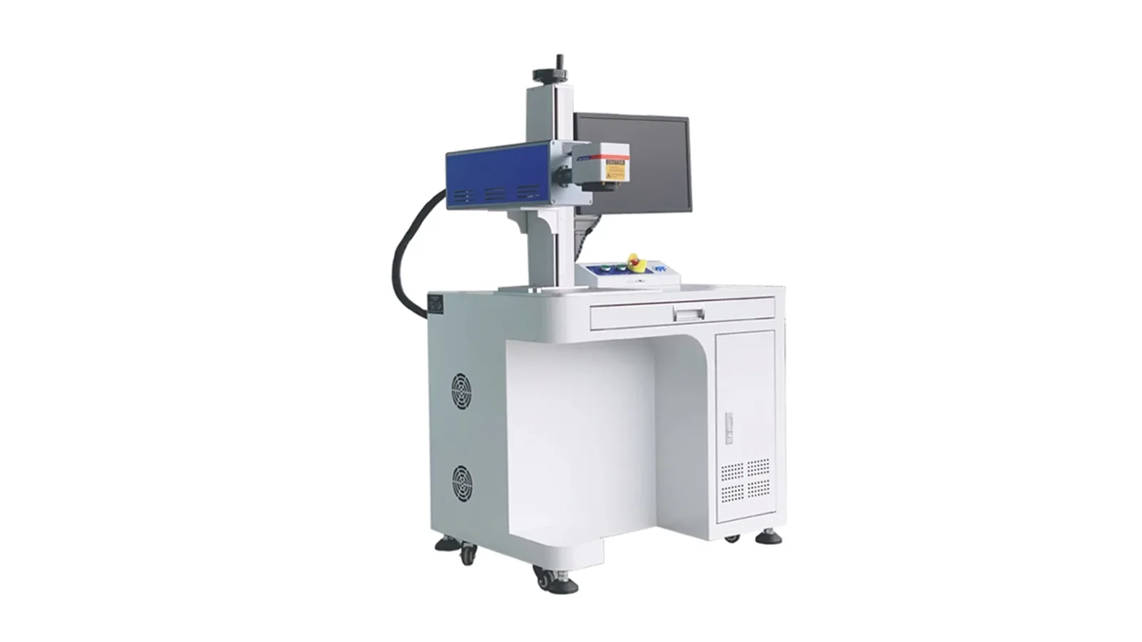
| Exposed resin, gel coat or paint where controlled surface change is acceptable | CO2 | CO2 commonly couples with many organic resin and coating systems, so it can be a practical first comparison for surface modification. | Charring, coating lift, resin recession, broad heat effect, dust or insufficient contrast can move the test toward another route. |
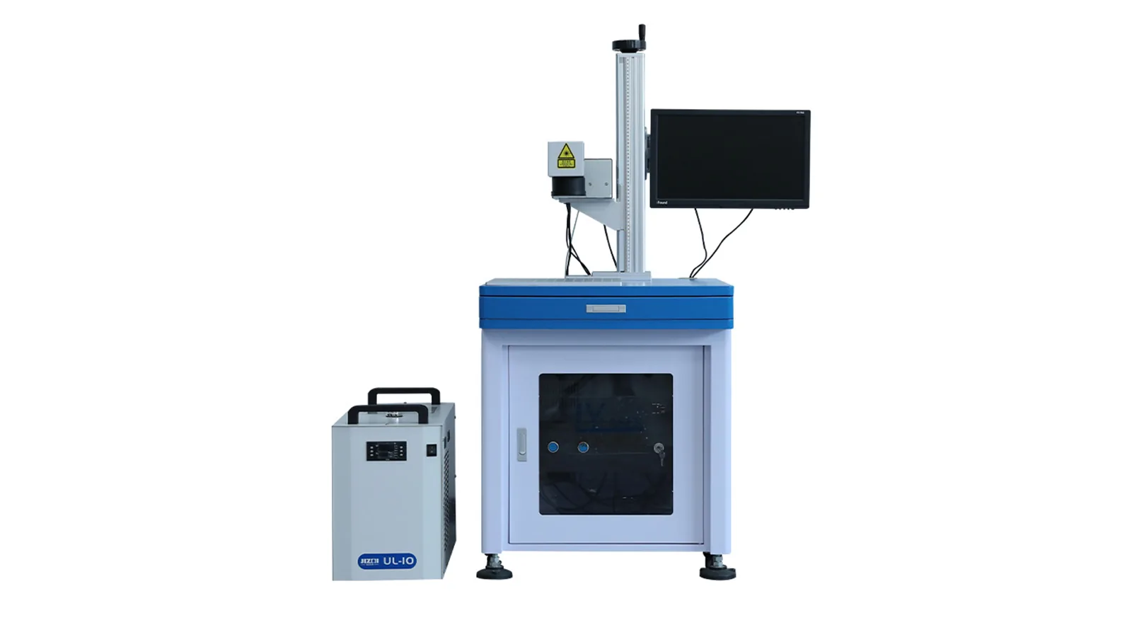
| Fine features or tight visible-heat limits on selected coating or resin-rich surfaces | UV | UV can be worth screening when a finer interaction zone or lower visible thermal impact is important. | UV is not automatically damage-free; discoloration, debris, chemistry, speed and durability still have to pass on the final laminate. |
| Pigmented, filled or coated surface with demonstrated near-infrared response | Fiber / MOPA fiber | Near-infrared fiber routes may work when the exposed constituent absorbs sufficiently and produces the required contrast. | The word “fiberglass” does not make fiber laser the default. Poor absorption, fiber exposure or inconsistent color response can rule it out. |
| Unknown construction, mixed surface or no reliable absorption history | Controlled comparison | Do not guess from the material name. Use a small route/parameter matrix on the finished part or a traceable production-equivalent coupon. | Choose the route that meets contrast, surface integrity, debris, durability and functional acceptance with the widest stable process window. |
Risk map
What Are the Common Risks and Failure Modes?
Increasing energy can improve apparent contrast while making the laminate less acceptable. Diagnose the failure mode before increasing power or dwell.
Resin Recession
The matrix can retreat before the glass reinforcement, leaving a rough halo, uneven depth or exposed strands.
Fiber Exposure and Fray
Woven, chopped or roving fibers can become visible, loose or difficult to clean even when the characters remain readable.
Delamination or Subsurface Damage
Localized thermal or mechanical stress can damage the resin-fiber interface or a nearby layer without being obvious from contrast alone. Functional parts may need additional inspection beyond a front-view photo.
Coating Lift, Edge Burn or Discoloration
Gel coat or paint can lift outside the intended mark, discolor at the boundary or lose adhesion after cleaning or handling.
Dust, Loose Fiber and Redeposition
During sample tests, record loose-fiber severity, visible dust, redeposited material after extraction and residue that remains after the specified cleaning method.
False Positive From One Coupon
A clean mark on one color, supplier lot or resin-rich coupon does not approve another laminate schedule, finish or batch.
Safety and extraction boundary
Treat the Marking Cell as an Industrial Laser Work Area
Safety review should cover the laser source, enclosure or guarding, extraction, abnormal conditions and the actual work area. The site safety officer and applicable local requirements govern the final installation.
Radiation and Reflections
Laser marking sources may emit invisible infrared or ultraviolet radiation. Control direct, specular and diffuse exposure paths from the workpiece, fixtures and nearby surfaces according to the selected source and cell design.
Guarding and Stops
For an automated cell, define a guarded enclosure, door interlocks, a safety circuit and an emergency stop. Assess open Class 4 or handheld work areas separately.
Dust, Fumes and SDS
Glass particles, resin decomposition products, coatings and additives require the exact Safety Data Sheet (SDS), local extraction, filtration and housekeeping controls.
Evidence quality
What Evidence Should Confirm a Fiberglass Mark?
Evidence should answer a different question from the sample-test procedure: not how the test was run, but whether the claimed result is traceable to the actual laminate and strong enough to support a production decision.

Traceable Material Record
Identify the resin, reinforcement, surface finish or coating, color, supplier or batch and the exact area that will be marked.
Traceable Marked Result
Use a final-grade part or production-equivalent coupon with a sample ID, visible result, laser route and enough test context to explain both acceptable and failed observations.
Acceptance Evidence
Confirm the required appearance or code readability together with fiber integrity, cleaning condition, durability and any finished-part functional checks that matter to the application.
Sample qualification
How Should a Fiberglass Sample Be Tested and Evaluated?
Record the construction, target result and rejection criteria before changing laser parameters. A useful test should show not only which settings produce contrast, but which process window remains acceptable after cleaning, handling and the required finished-part checks.
Identify the Part
Send final-grade parts or traceable production-equivalent coupons with resin system, glass form, coating, color, thickness, supplier/batch information and SDS where available.
Define Acceptance
Provide artwork, code size, target contrast, protected zones, scanning needs, durability requirements and whether any exposed fiber, texture change or residue is acceptable.
Compare the Process Window
Run a controlled route and parameter matrix. Record both acceptable and failed settings rather than choosing one visually good point.
Inspect the Mark and Debris
Check readability, edge heat, fiber exposure, delamination indicators, loose fiber, visible dust, redeposition, post-cleaning residue and required durability.
Confirm Part Function and Transfer
Verify any application-specific function affected by the marked zone, repeat on representative batches, then carry the approved window into fixture, extraction, enclosure, data and cycle-time decisions.
From sample result to equipment
How Is the Final Machine Configuration Chosen?
The approved sample window should drive the equipment specification. The material name alone is not enough to choose power, lens, fixture, enclosure or automation.
Lock the Laser Route
Use the sample result to confirm the laser family and the control range needed to reproduce the acceptable mark without unacceptable fiber or heat damage.
Match Source Capability to the Process Window
Select the source configuration and available power/control range from the tested process, feature size and cycle requirement rather than from a generic fiberglass recommendation.
Choose Field, Lens and Focus Strategy
Mark size, required detail, curvature and height variation determine field size, working distance and whether fixed focus, rotary handling, repositioning or 3D focus control should be evaluated.
Define Part Handling and Fixture
Part size, stiffness, mark location and repeatability determine the worktable, support, fixture, rotary, motion or custom positioning requirement.
Size Extraction and Safety Controls
Use the observed dust, loose fiber, resin products and workcell arrangement to define local extraction, filtration, enclosure, interlocks and related safety review.
Confirm Data, Cycle and RFQ Inputs
Finalize code data, trigger/interface needs, operator workflow, target cycle time and acceptance criteria. The quote can then be based on a tested material response and a defined production task.
FAQ
Fiberglass Composite Laser Marking Questions
Can a laser marking machine mark fiberglass composite?
It can be screened, but feasibility depends on resin, glass form, coating, color, cure and target effect. A generic fiberglass label is not enough to select a source.
Is a fiber laser the default choice for fiberglass?
No. Fiber/MOPA is not the default simply because the material contains glass fiber. CO2, UV, fiber/MOPA or a controlled comparison should be selected from the exposed surface, absorption response and target result.
Why does the mark expose glass fibers?
The resin matrix can respond before the reinforcement. If energy or dwell is too high, resin recession reveals or roughens the glass strands.
What are the main dust and fume concerns?
Glass particles, resin decomposition products, coatings and additives should be reviewed from the exact SDS and addressed with suitable extraction and filtration.
Does a good-looking sample mean the finished fiberglass part is approved?
No. The sample also needs the required checks for fiber integrity, debris, cleaning, durability and any finished-part function that could be affected by the marked area.
What evidence is required before specifying a machine?
Use identifiable final-grade samples, construction/SDS records, visible marked results, test conditions, failure observations and acceptance checks across representative batches.
Prepare a useful review
Send the Exact Fiberglass Construction and Acceptance Target
Include representative finished samples, resin and glass details, coatings or adhesives, artwork, mark area, target result, protected zones, part dimensions, durability or functional checks, cycle target and extraction constraints.