
Connector and Terminal Laser Marking
Permanent marking for connector housings, terminals and crimp ends — brand, part number, polarity, batch and Data Matrix codes, placed where they stay readable without touching contact or conductive areas.
This page helps you turn a connector or terminal marking requirement into a testable production brief: identify the part and marking purpose, define the required visual, code and functional result, account for surface, geometry and loading, choose a laser direction for sample testing, then use the acceptance results to determine fixturing, verification and the final machine configuration.
Connector and Terminal Laser Marking at a Glance
Yes — laser marking is an established method for putting permanent identification on connectors and terminals. In electronics and electrical manufacturing, connector housings are typically marked with brand, part number, date and lot codes and Data Matrix symbols, while terminals and pins carry terminal numbers, polarity marks and traceability codes. The practical question is not whether it can be done, but what your part needs, where the mark can safely go, how the part geometry should be held, and which laser direction to evaluate first.
Material behaviour — why copper, brass, plating and plastic grades respond differently — belongs to the dedicated material pages linked throughout, not to this page. If your question is about PCB or individual electronic components, those are separate application pages under the same Electronics & Electrical section.
Which Connector and Terminal Parts Are Commonly Marked?
Start by identifying the exact part family, the available mark face and the functional areas that must stay untouched. Connector housings, terminals, pins, crimp barrels and terminal blocks differ in size, access, geometry and how they are presented to the marking station.
Connector housings
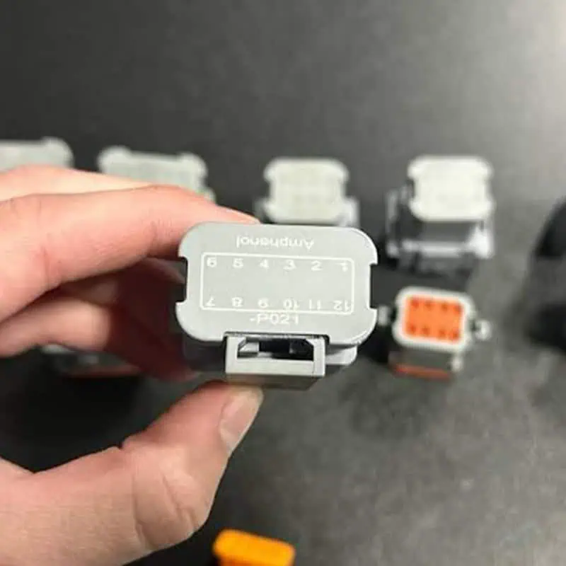
Connector housings may be plastic or metal and usually provide the largest available marking area. The practical questions are which outer face remains visible after assembly, whether ribs, latches or seals restrict access, and whether the part can be located repeatably in a tray or fixture.
Terminals and pins
Terminals and pins offer much less marking area than housings and may be flat, formed or cylindrical. The usable face is usually a visible side surface above the mating/contact zone, so orientation after insertion and repeatable presentation to the laser become part of the application design.
Cable crimp and wire-side ends
Crimp barrels and wire-side ends are small, formed features with limited flat area. Their suitability depends on whether the side face can be exposed without disturbing the wire, conductor or crimp function, and whether the part arrives loose, in a strip, reel or assembly.
Why Are Connectors and Terminals Marked?
The marking requirement should be defined before the laser route. A connector may need a visible assembly identifier, a machine-readable traceability code, or both — and each purpose changes what must remain readable, where the mark can go and how the sample should be accepted.
| Why the part is marked | Typical content | What it changes in the marking requirement |
|---|---|---|
| Part identification | Brand, part number, customer part number | Visible location, legibility and consistency after assembly |
| Assembly and orientation | Terminal position, polarity, cavity or connection identifier | Mark position and viewing direction become critical |
| Lot and production traceability | Date code, lot code, batch identifier | Data accuracy and durable readability matter across the production flow |
| Unit-level serialization | Serial number, Data Matrix or QR code | Feature size, reader performance, data transfer and post-mark verification must be evaluated |
| Inspection, service or downstream handling | Rating, status, service or process identifier when required by the drawing/program | The mark must remain accessible and readable at the downstream inspection or service point |
Not every connector needs every type of mark. Start from the drawing, customer specification or traceability requirement, then define the mark content and acceptance criteria around that purpose.
What is usually marked?
| Part family | Typical mark content | Typical location |
|---|---|---|
| Connector housing (plastic/metal) | Brand, part number, date/lot code, Data Matrix / QR | Flat outer face, top or side |
| Terminal / pin | Terminal number, polarity, batch code | Terminal side, above the contact zone |
| Crimp barrel / wire-side end | Lot or traceability code | Flat side of the crimp area |
| Terminal block / screw terminal | Position number, voltage/rating marking | Insulation body, visible face |
Whether the content is defined by the customer’s drawing, an industry standard or an internal traceability rule changes what the marking station must be able to do. When the code value is generated by a serial-number database or MES and must be verified after marking, the data-flow design belongs to the traceability and data integration solution rather than to this application page.
What Determines Laser Marking Results on Connectors and Terminals?
The material name alone is not enough to choose the process. The result is set by the combination of material and surface, mark size, target effect, optical access, positioning repeatability and the way the mark will be inspected in production.
Material, colour, plating and surface condition
A plastic housing can change response with resin grade, colour, filler or additive package; a terminal can change response with alloy, plating and surface finish. Copper, brass, plated metal and engineering plastics therefore need to be evaluated as actual surfaces, not only as generic material names. Detailed material behaviour is covered on the copper, brass, plated metal and plastics pages.
Mark content, available area and minimum feature size
A logo on a broad housing face is a different optical task from a compact Data Matrix on a narrow terminal side. Character height, code module size, data density, line width and the available mark area determine how fine the process must remain across the batch. The useful limit is not the smallest feature that can be produced once, but the smallest feature that remains repeatable and readable with the intended inspection method.
Target effect and allowable surface change
Dark-on-light contrast, light marking on a dark surface, shallow colour change, annealing or deeper engraving are different targets. The acceptable amount of heat input, surface removal or plating change must also be defined, especially near contact, sealing or mechanically stressed areas.
Geometry, focus and optical access
Curvature, cavity depth, height variation, ribs and multi-face geometry can move the mark away from the intended focal condition or block optical access. These variables determine whether the part can be handled with a simple fixture or needs rotary indexing, Z adjustment, vision or another custom arrangement.
Positioning, verification and durability
Fixture repeatability and part orientation determine mark-position consistency. If the content is machine-readable, the production reader, lighting and required verification method also become part of the result. If the mark must survive abrasion, solvents, heat or repeated handling, those exposures must be included in sample acceptance rather than assumed from appearance alone.
What Marking Result Should You Target?
Define the acceptable result before comparing lasers. For connectors and terminals, a good mark is not simply one that looks dark or sharp — it must meet the visual, code, positional, functional and durability requirements of the real part.
| Result dimension | What to define | Why it matters |
|---|---|---|
| Visual result | Required contrast, character clarity and viewing direction | Human-readable identifiers must remain clear after assembly |
| Code result | Code size, reader, lighting and any required verification or grading method | A code that looks acceptable may still fail production reading |
| Surface result | Colour change, annealing, shallow mark or engraving depth as applicable | The required appearance changes source and parameter direction |
| Position result | Allowed mark-position tolerance and final viewing access | Fixture, tray, vision or indexing requirements follow from this tolerance |
| Functional result | No unacceptable change to contact, plating, seal, wall strength or mating function | Functional surfaces and keep-out zones take priority over appearance |
| Durability result | Required resistance to handling, abrasion, solvent, heat, humidity or mating cycles | Acceptance must reflect the actual service or downstream process |
| Batch result | Consistency across parts, trays, lots and shifts | The process must be repeatable, not only successful on one sample |
The customer drawing, program requirement or internal quality plan should supply the pass criteria where they exist. Where no formal criterion exists, the sample test should still record the agreed visual, functional and production acceptance conditions before a machine configuration is finalized.
Where to Mark and Where Not to Mark
Position is a design decision as much as a laser decision. The working rule for connectors and terminals: mark on flat, visible, non-functional surfaces, and never on contact or conductive areas where the mark could change electrical or mechanical behaviour.
Contact and conductive areas are keep-out zones
Terminal contact surfaces — the mating zone, spring contacts, conductive paths and any area that carries current or makes an electrical connection — must be kept clear of laser marking unless the part specification explicitly allows the process there. Laser processing can change plating, surface finish, roughness or local geometry; on a functional contact area, those changes can affect electrical contact or mating behaviour. The exact keep-out definition therefore comes from the part drawing and the applicable specification.
Safe zones
- Flat housing faces — the standard target for brand, part number and codes; easy to mark, easy to scan after assembly.
- Terminal side wall above the contact zone — visible after insertion, clear of the mating surface.
- Crimp barrel side face — flat enough for a small code, away from the wire strand area.
Keep-out zones
- Contact surfaces and conductive paths — marking can change surface finish, plating or contact resistance.
- Sealing and gasket areas on sealed connectors — a mark that disturbs the sealing surface can affect IP rating.
- Highly stressed or flexing areas — on thin plastic walls or cable transitions, a deep mark can weaken the structure.
- Areas covered later by overmolding or potting — if the mark will be covered, verify readability through the covering material.
Positioning and part presentation
Where the mark goes also depends on how the part is presented to the laser. A housing in a tray can be positioned by a simple fixture; a cylindrical terminal needs to be indexed so the laser reaches the right face; small terminals in a strip or reel may need a feed system. For alignment and positioning methods, see the vision positioning solution; for cylindrical parts, see the rotary marking solution.
Geometry, Fixturing and Positioning
Connectors and terminals come in shapes that do not sit flat under a laser: cylindrical terminals, deep housings, multi-face bodies and small parts in trays or reels. The geometry of your part decides whether a simple bench fixture is enough or whether rotary, vision or a feed system is needed.
Cylindrical terminals and rotary marking
Pins, posts and cylindrical terminals are usually marked around the circumference on one or more faces. A rotary axis indexes the part so the laser reaches each face in sequence with one set-up, keeping position repeatable from part to part. For parts marked on a single flat side, a simple stop or V-groove fixture may be enough. The system method for rotary marking — axis selection, indexing and part holding — is covered on the rotary & circumferential marking solution.
Irregular housings, trays and custom fixtures
Housings with ribs, latches or non-flat outer surfaces need a fixture that locates the part repeatably and exposes the mark face. Tray-based loading is common for small parts: a tray holds dozens of housings in defined pockets, and the marking station steps through the tray. For multi-face marks, the part must be re-positioned or the station needs more axes. Fixture repeatability directly affects mark position consistency, so it is a production-quality decision, not a convenience.
Random placement and vision positioning
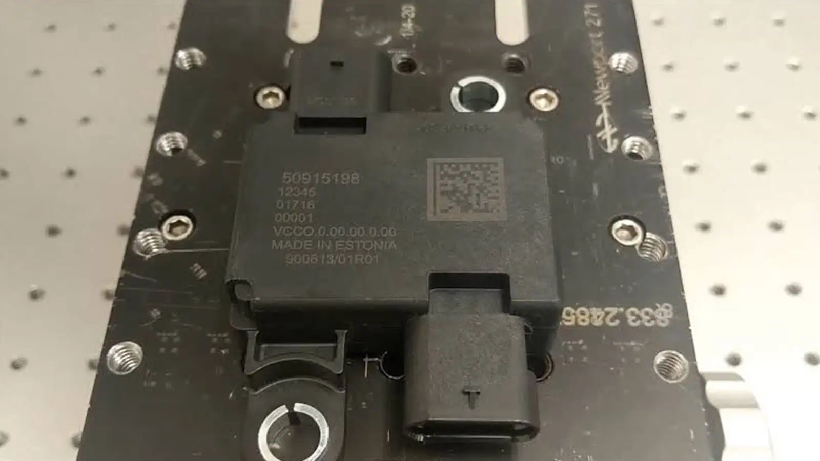
When parts arrive with variable XY position or rotation — for example on a conveyor or without a precision tray — a camera can locate the mark position before the laser fires and correct within the available field. This can reduce dependence on precision XY fixturing, but it does not by itself solve height variation, focus, tilt or blocked optical access. The system method is covered on the vision positioning solution.
Fixture and configuration decision
| Part geometry | Typical holding method | Configuration direction |
|---|---|---|
| Flat housing, one face | Simple fixture / tray pocket | Bench machine, manual load |
| Cylindrical terminal, multi-face | Rotary axis / index | Rotary configuration |
| Random orientation on conveyor | Camera + laser positioning | Vision configuration |
| High volume, small parts | Tray feed / vibratory feed | Automatic feeding / cell |
| Deep cavity or steep draft | Angled head / longer focal position | Custom worktable / evaluation |
This table gives direction, not a finished answer — the right configuration is confirmed with your part, your rate and a sample test.
Which Laser Direction to Evaluate First
Laser choice for connectors and terminals commonly starts with fiber/MOPA around the 1064 nm range for many metal and plated parts, and UV around 355 nm for heat-sensitive plastics. Highly reflective copper surfaces are more conditional: suitable IR/MOPA, UV or green sources may need to be compared depending on the surface condition, required contrast and thermal limits. The final direction must be confirmed on the actual part.
Metal housings, terminals and plated parts
For brass, bronze, steel and many plated terminals, fiber/MOPA is commonly one of the first directions to evaluate. Copper needs a more conditional decision because its response at conventional 1064 nm is strongly affected by surface condition and pulse characteristics. A suitable pulse-controlled IR/MOPA source can work on copper, but UV or green may also be relevant when absorption, contrast or thermal control makes them a better match. For a copper terminal, choose the route from the actual surface and target effect rather than assuming that one laser family is always the default. The detailed material behaviour remains the scope of the copper, brass and plated metal material pages.
Plastic housings and heat-sensitive parts
For plastic housings — PA, ABS, PC, PBT and glass-filled grades — UV is often the first direction to evaluate when the goal is a clean, low-heat mark on a heat-sensitive or dark resin. Fiber marking of dark plastics can produce carbonisation or foaming, which may be acceptable for contrast in some cases but is a process the sample test must confirm. Whether a plastic grade marks white, dark or not at all depends on the resin and its additives, which is material behaviour covered on the plastics material pages (including nylon/PA and glass-filled grades).
When contrast and depth goals change the choice
The target effect changes the direction: a light, high-contrast mark on a dark housing, a dark annealed mark on metal, a shallow surface mark versus a deeper engraved mark, or a mark that must survive abrasion — each points to a different setting and sometimes a different source. Defining the target effect first avoids choosing the machine around the wrong goal.
Direction table
| Part material / surface | Direction to evaluate first | Why (conditioned) | Material page |
|---|---|---|---|
| Brass / bronze terminal | Fiber / MOPA | Absorption at 1064 nm varies with surface state | Brass marking |
| Copper terminal / conductor | Case-specific: IR/MOPA, UV or green | Highly reflective copper makes the response strongly dependent on wavelength, pulse characteristics and surface state; compare on samples | Copper marking |
| Tin / silver / nickel plated | Fiber / MOPA | Plating layer governs the response | Plated metal marking |
| PA / ABS / PC / PBT housing | UV first, fiber conditioned | Heat-sensitive resins; additive-dependent | Plastics & polymers |
| Anodized aluminium housing | Fiber / MOPA | Anodized layer response depends on colour | Anodized aluminium marking |
The laser family that fits your part, and the machine configuration around it, is confirmed with a sample test. Machine families and specification ranges are covered on the fiber laser marking machines and UV laser marking machines product pages.
What Are the Common Connector and Terminal Marking Failure Modes?
Sample testing should be designed to expose the failure modes that matter in production, not only to produce one visually attractive sample.
| Failure mode | Typical cause or condition | What to check |
|---|---|---|
| Low or unstable contrast | Material formulation, colour, plating or surface condition varies | Compare representative lots and define an acceptable contrast/readability window |
| Plating or surface damage | Excessive energy or an unsuitable target effect on a thin functional layer | Inspect the marked area and keep functional contact zones outside the process unless explicitly approved |
| Plastic melting, excessive foaming or deformation | Thermal input is too high for the resin, wall thickness or target result | Compare laser route and parameters on the actual moulded grade |
| Code cannot be read reliably | Modules are too small, contrast is weak, distortion is high or reader conditions differ | Verify with the production reader and required method, not by visual inspection alone |
| Mark-position drift | Fixture, tray, feed or orientation is not repeatable | Measure position across multiple parts and review locating features or vision correction |
| Out-of-focus or incomplete marks | Height variation, curvature, cavity depth or blocked optical access | Check the full part geometry and whether Z, rotary, 3D or fixture changes are needed |
| Durability failure after handling or exposure | The visible mark does not meet the real abrasion, solvent or temperature requirement | Run the defined exposure test and re-check legibility/code readability |
| Production rate is not achieved | Loading, locating, verification or reject handling dominates the cycle | Measure the complete cycle rather than laser scan time alone |
How Does Connector and Terminal Marking Fit Into Production?
Production readiness depends on the whole flow: how parts arrive, how they are located, how data is supplied, how the mark is verified and what happens to accepted or rejected parts. Laser scan time is only one part of that cycle.
1. Load and present the part
Parts may be loaded manually, placed in trays, supplied on strip or reel, fed from a bowl, or presented on a conveyor. The loading method must preserve the mark face and orientation required by the process.
2. Locate, clamp and confirm the mark position
A fixed tray or fixture is appropriate when part presentation is repeatable. Rotary indexing is used when the required mark face changes around a cylindrical part. Vision can reduce dependence on precision XY orientation when part height, optical access and the allowable correction range remain controlled.
3. Supply the marking data and run the laser process
Static part numbers can be loaded from a saved job. Variable serial, lot or code data may come from the operator, a database or an MES/line system. The selected laser route and parameter set must correspond to the correct part and surface condition.
4. Verify the mark and handle rejects
If downstream scanning is required, the code should be read after marking and compared with the intended value. A production cell may also need pass/fail logic, reject handling and trace records. Data architecture and serialization logic are covered on the traceability and data integration solution.
5. Measure the complete cycle and batch consistency
The real cycle includes loading, locating, clamping, marking, verification, reject handling and unloading or transfer. Tray handling or part feeding can dominate high-volume production, so cycle time should be measured with the intended loading method and representative batch rather than inferred from scan time.
6. Review line integration, extraction and safety controls
Inline stations may require triggers, sensors, conveyor coordination, automatic feeding or a dedicated marking cell. Plastic marking can also generate fumes or decomposition products depending on resin and additives, so extraction or ventilation should be reviewed with the final machine and process arrangement. Relevant system routes include flying & online marking and the automatic marking cell.
Sample Validation and Acceptance
For connectors and terminals, a sample test is not a formality — it is the step that settles contrast, mark size, durability and cycle time on your actual part. Zhuorui Laser supports sample marking, parameter setup and fixture review as part of the evaluation process.
What to prepare for a sample test
- Part material and surface state — resin grade or metal alloy, plating, anodising, colour.
- Product drawing or photo — mark location, geometry, keep-out areas.
- Mark content and size — text, logo, Data Matrix / QR content, character or code size.
- Target effect — dark on light, light on dark, depth, contrast level.
- Production rate and batch size — cycle-time target, volume.
- Part presentation and loading method — loose parts, tray, strip or reel, conveyor, existing fixture and required orientation.
- Data and verification requirement — fixed or variable content, human-readable only or scanner verification, serial/MES data exchange and reject handling when required.
- Environmental requirements — temperature, solvent, abrasion, mating cycles.
- Sample quantity — enough parts for marking plus any durability testing.
Acceptance dimensions
| Dimension | What to confirm |
|---|---|
| Contrast and legibility | Mark readable at the required viewing angle and lighting |
| Character / code size | Minimum feature produced reliably on the part |
| Code readability | Verified with the reader used in production (grade method per customer) |
| Position repeatability | Mark position consistent across parts in the fixture |
| No functional damage | Contact areas untouched; no unacceptable plating, roughness or geometry change; no structural weakening |
| Durability | Passes the defined abrasion / solvent / temperature tests |
| Cycle time | Measured on real parts with the real loading method |
Once these acceptance points are recorded, use the results to decide the final source, optics, fixture, positioning, verification and handling configuration in the next section. Automated, vision or data-integrated requirements should be carried into the project scope rather than assumed from the laser source alone.
How Do Sample-Test Results Determine the Final Machine Configuration?
The sample test should close the selection loop. Its purpose is not only to approve the mark, but to show which source, optics, positioning, handling, verification and production features are actually required for the accepted result.
| Sample or production finding | Configuration implication | What still needs confirmation |
|---|---|---|
| A UV route gives the required plastic contrast with acceptable surface/thermal effect | UV laser direction | Required field, cycle time and enclosure/workstation arrangement |
| Fiber/MOPA meets the result on the actual metal or plated terminal | Fiber/MOPA direction | Power/pulse configuration, optics and production rate for the approved surface |
| A small code needs finer features than a broad logo or text mark | Optical field/lens selection must protect the required feature size | Usable marking area and reader performance across the batch |
| Fixture loading holds position within the accepted tolerance | Simple fixture or tray-based machine may be sufficient | Operator loading method and changeover requirements |
| Part rotation or multi-face access is required | Rotary/indexing configuration | Holding method, index sequence and total cycle |
| XY orientation varies between parts | Vision positioning may be evaluated | Height variation, optical access and correction range still need control |
| Manual/tray handling cannot meet the required production rate | Automatic feeding, conveyor or marking-cell evaluation | Interface, buffer, reject and changeover logic |
| Each DPM code must be verified and linked to production data | Reader/vision, serialization and data-integration functions | Data source, verification method, pass/fail response and trace record |
| Process fumes require controlled removal | Extraction/ventilation becomes part of the machine or cell configuration | Actual material/process emissions and site requirements |
The preferred outcome is the simplest configuration that repeatedly passes the agreed sample and production acceptance criteria. If the required result needs rotary, vision, automatic feeding or data integration, those functions should be specified because the test demonstrated a need for them — not added by default.
FAQ
Can laser marking damage terminal contact surfaces?
Marking on contact or conductive areas is avoided as a general discipline because laser processing can change plating, surface finish, roughness or local geometry on a functional surface. Those changes may affect electrical contact or mating behaviour. The keep-out definition comes from the part drawing and the applicable specification, and sample marking should stay within approved non-functional surfaces.
Why does marking contrast differ between copper, plated and plastic housings?
Each material responds to laser energy differently — copper and brass absorb less at 1064 nm, plating layers change the response, and plastic grades react according to their resin and additives. This is material behaviour, covered in detail on the copper, brass, plated metal and plastics material pages.
Do cylindrical terminals need a rotary axis?
Not always. A single flat side can be marked with a simple fixture; a terminal that needs marks on several faces is more repeatable with a rotary axis that indexes each face in one set-up. The decision depends on the mark faces and the volume, and is confirmed in the sample test. See the rotary marking solution for the system method.
Can the mark survive high temperature, solvents and repeated mating?
It depends on the material, the surface and the laser parameters — a mark that survives on one surface may fail on another. Durability is verified by defined tests on real samples (abrasion, solvent, temperature cycling, re-reading the code). This page does not guarantee a universal durability level; the sample test establishes it for your part.
Which laser should I evaluate for small connector housings?
For plastic housings, UV is often the first direction to evaluate when a clean, low-heat mark is the priority. For many conventional metal and plated housings, fiber/MOPA is a common starting point. Copper and other highly reflective surfaces should be treated separately and may require comparison between suitable IR/MOPA, UV or green approaches. The final choice depends on the actual resin or metal surface, colour, plating and target effect, and is confirmed on a sample.
Can marking be integrated into an existing assembly line?
Yes, when the line layout and rate require it — with trigger signals, positioning, read verification and data exchange with the production system. Integration scope is reviewed as a project (see the flying & online and traceability solutions, and the OEM & custom inquiry path), not assumed from a machine description.
Sample Test or Quotation
If your part is a connector, terminal or crimp end, the fastest way to settle the process is a sample test with your material and mark content. Zhuorui Laser can review the application, mark representative samples, set parameters and confirm the configuration direction.