
Medical & Dental Applications
Laser Marking for Medical Implant Components
Permanent UDI, batch, serial and size identifiers on orthopedic and dental implant components — reviewed for traceability, material impact and regulatory input, then validated through the processing the implant actually undergoes.
- UDI-DI / UDI-PI, batch, serial and size identifiers on small components
- Material-impact review for load-bearing titanium, stainless and polymer parts
- Sample-first validation through the actual downstream processing and sterilization route
Quick Answer
Laser Marking for Implant Components: Traceability on Tiny, Load-Bearing Surfaces
Implant components — orthopedic screws, trauma plates, hip stems, dental abutments and related devices — can be laser-marked with permanent identifiers such as UDI data, batch and serial numbers, and size or direction markers. The useful question is not simply whether a laser can make a mark. The project has to define why the component is marked, what content must fit, what material and surface conditions control the result, what result will be accepted, how the part will be positioned and handled, which laser route should be tested first, and how the sample result will determine the production configuration.
This page follows that decision from application definition to equipment commitment: why implant components are marked, what is usually marked, which variables control the result, what a successful mark must achieve, how geometry and part handling affect the workstation, which laser route enters the first trial, what can fail, how the mark moves into production, how the sample is accepted, and how the accepted test result maps to the final machine configuration. Material response details belong to the material pages; UDI data-system engineering belongs to the UDI and data-integration pages; machine models belong to the product pages.
Why Mark
Why Are Medical Implant Components Marked?
Implant-component marking is used when the physical part needs a durable identity that can stay connected to manufacturing, quality and device records. The reason for the mark should be defined before the code format or laser source, because a traceability identifier, a size or orientation mark, and a device-level UDI requirement do not create the same content, verification or documentation task.
| Reason for marking | What the mark needs to do | Project implication |
|---|---|---|
| Manufacturing and batch traceability | Link the physical component to lot, serial or production records | Controlled data, repeatable placement and record retention may be required |
| Part identification | Show size, type, orientation or other device information on the component | Available area and human readability become primary constraints |
| UDI / regulatory identification where applicable | Carry the required device and production information in the specified carrier | Regulatory scope, symbol format and verification criteria must be defined before process validation |
| Brand or manufacturer identification | Add a durable logo or manufacturer mark without compromising the device surface | Appearance matters, but material impact and placement remain part of acceptance |
Start with the marking purpose, not the machine. Once the project owner has defined why the part needs a permanent mark, the marking engineer can translate that need into content, size, placement, verification and validation requirements.
What Is Marked
What Is Usually Marked on Implant Components?
After the marking purpose is defined, specify the exact content, code format, size and placement that must fit on the component. Those inputs determine how much usable marking area is required and what the later verification step must evaluate; they should be fixed before comparing fiber, MOPA or UV routes.
Component types and typical mark content
| Component category | Typical examples | Typical mark content |
|---|---|---|
| Orthopedic and trauma | Bone screws, plates, intramedullary nails, hip stems, ball heads, acetabular cups | UDI-DI / UDI-PI, lot and serial numbers, size, torque or direction markers, logo |
| Dental | Dental implants, abutments, healing caps, bridge frameworks, drill guides | Implant size and type code, lot number, logo, occasionally UDI components |
| Spine and other load-bearing | Pedicle screws, rods, interbody cages | Size, lot, serial, orientation markers, logo |
Label marking versus direct part marking
A UDI system normally includes a carrier on the label or packaging. Whether the device itself must also carry a permanent UDI is determined by the target-market rule; implant status alone does not trigger a direct-marking requirement. In the United States, FDA 21 CFR 801.45 applies the direct-mark requirement to devices that must bear a UDI on the label and are intended for more than one use and to be reprocessed before each use. EU MDR likewise sets device-level UDI carrier requirements for reusable devices, subject to stated exceptions. For an implant project, the manufacturer’s regulatory team should first confirm whether a device-level direct mark is required or otherwise desired; the marking engineer’s job is then to make that specified mark technically feasible and readable. The UDI marking page covers the data structure behind these identifiers.
Space is the first constraint
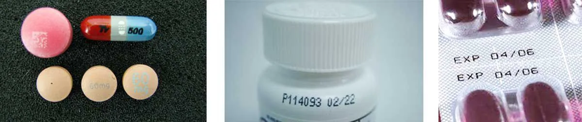
Implant marking surfaces are often very small — a screw flank, a stem neck, a cup rim — so the practical question is not “what do we want to print” but “what fits in the available flat or gently curved area at a readable size.” On small titanium components, the usable Data Matrix size must be established on the actual part: available area, module size, material response, beam quality, focus and geometry all affect whether the code can be verified reliably.
When direct part marking is not the right answer
Laser direct marking is the right route when the device needs a permanent identifier on the component itself. It is not automatically the right route when the available surface cannot hold a readable code at a usable size, when the downstream treatment chain is expected to remove or damage any surface mark, or when the target-market rules for the device category allow identification on the label or packaging alone. In those cases the evaluation should fall back to a label or packaging identification path — direct marking should be chosen because the device needs it, not because it is available.
Related application routes: surgical instrument marking covers reusable surgical tooling, dental instrument marking covers reusable dental tooling, and medical plastic components covers polymer device parts where different heat constraints apply.
Regulatory Input
How UDI Direct Part Marking Requirements Affect Implant Components
Implant marking projects carry a compliance dimension that shapes the marking content, the verification grade and the documentation. This page gives the engineering context; it is not legal or regulatory advice, and the final determination for a specific device belongs to the manufacturer’s regulatory team for the target market.
How UDI requirements translate into marking work
- UDI-DI and UDI-PI: the Device Identifier identifies the model and manufacturer; the Production Identifier carries lot, serial, expiry or similar data. Both belong in the UDI carrier where required, and the split matters for the data workflow.
- Direct marking: implant status alone does not determine whether a device-level UDI mark is required. The manufacturer must confirm the applicable target-market rule, device classification, reuse or reprocessing conditions where relevant, and any available exceptions before the laser process is specified.
- Machine-readable form: the carrier format follows the applicable issuing-agency and market requirements. GS1 DataMatrix is a common AIDC route for medical-device direct marking, while human-readable information is included where the applicable specification requires or supports it. For direct part marks, verification should use the applicable 2D and DPM quality method — including ISO/IEC 15415 and ISO/IEC 29158 where relevant — and the mark must remain readable after the actual processing the device undergoes.
- Process validation: where the manufacturer’s quality system requires the marking process to be validated, the qualification may be structured as IQ/OQ/PQ or another documented validation approach appropriate to that process, with controlled parameters and defined acceptance criteria.
| Regulatory input | What it drives | Where it is confirmed |
|---|---|---|
| UDI-DI / UDI-PI structure | Data content and code structure | UDI marking page; issuing-agency rules (e.g. GS1) |
| Direct-marking requirement | Device-level direct mark vs label only | Manufacturer regulatory team / target-market rule |
| 2D / DPM symbol quality (ISO/IEC 15415; ISO/IEC 29158 where applicable) | Verification method, illumination and acceptance grade | Issuing-agency specification; current verifier procedure and applicable standards |
| Process validation / qualification | Controlled parameters, acceptance criteria and documented qualification where required | Manufacturer’s quality system and applicable regulatory framework |
Practical consequence before laser trials: confirm whether direct marking is required, what carrier/content must be applied, how the code will be verified and what validation/documentation expectations apply. Those requirements become inputs to the target-result definition and sample-test plan. Where production also needs controlled code generation, result logging or system connectivity, the traceability and data-integration solution covers that system layer.
Result Variables
What Determines the Laser Marking Result on an Implant Component?
The result is controlled by a combination of the part, the mark specification and the production process. Material name alone is not enough to select a machine: two components made from the same alloy can require different parameter windows when their surface finish, code size, curvature or downstream treatment changes.
| Variable group | Inputs to define | What they change |
|---|---|---|
| Material & surface | Material grade or polymer formulation, finish, color/coating, anodizing, blasting, etching, passivation or other treatment state | Absorption, contrast mechanism, thermal window, surface-response and durability questions |
| Mark specification | Text or Data Matrix content, symbol/module size, required contrast, depth if any, placement and verification criteria | Spot-size, field, beam-quality and process-window requirements |
| Geometry & presentation | Flat, cylindrical or curved area; available marking band; height variation; orientation; fixture contact limits | Focus stability, rotary/3D/vision need, fixture design and repeatability |
| Downstream process | Cleaning, passivation, coating and sterilization steps that actually apply to the device | Whether contrast, readability and surface condition remain acceptable after processing |
| Production conditions | Batch size, loading method, changeover frequency, verification, reject handling and data logging | Workstation layout, automation level, software/data integration and cycle workflow |
A useful RFQ or sample request therefore describes the actual part and process, not just “titanium implant marking.” At minimum, provide the material/surface state, mark content and available area, geometry and loading condition, required result, downstream process, production volume and verification requirement.
Material-Impact Review
Why Implant Marking Is Different: The Material-Impact Constraint
Marking an implant is not the same as marking a general metal part. The component is load-bearing, corrosion-sensitive, and may remain in the body for years. Laser marking concentrates energy into the surface; the question is what that energy changes and whether the change is acceptable for the intended device. This is the material-impact review, and it is the reason implant marking projects normally include a material or process engineer, not only a laser supplier.
What “material impact” means for implants
- Thermal input: every marking process deposits heat locally. On metals the result can range from an oxidation-based contrast mark to melting, recrystallization or residual stress, depending on pulse parameters and scanning strategy.
- Surface chemistry: on titanium, controlled laser annealing creates a thin oxide layer that gives the dark contrast mark. The oxide is chemically related to titanium’s own passive layer, but thickness and coverage are process-controlled — this is why parameter windows matter more than raw power.
- Mechanical and corrosion behavior: excessive heat or unwanted surface roughness can raise questions about fatigue, fretting or crevice corrosion on load-bearing implants. Whether a specific mark is acceptable is a device-level engineering judgment that a page cannot guarantee.
- Surface treatment sequence: whether the mark is applied before or after anodizing, bead blasting, acid etching, HA coating or other surface treatment changes both the achievable contrast and the durability of the mark.
Material review points by family
| Material family | Review points on this page | Detailed response |
|---|---|---|
| Titanium and Ti alloys | Oxide-based dark marking, heat-input control, fatigue and corrosion review points | Titanium laser marking — material page |
| Stainless steel | Annealed contrast marks, passivation compatibility, corrosion review | Stainless steel laser marking — material page |
| High-melting alloys (e.g. cobalt-chrome) | Higher energy required, thermal management, achievable contrast | Confirm on sample; material page route |
| Polymers (PEEK and medical plastics) | Low thermal budget, additive-dependent response, fume control | Plastics & polymers — material hub; medical plastics application page |
The important engineering rule: contrast alone is not the acceptance criterion for an implant mark. A mark that looks good but sits on a surface where heat has changed the material state can fail a device review. The evaluation should include the material response, the surface treatment sequence and the post-processing steps — and the parts of that assessment that depend on the specific grade and batch need sample-level confirmation.
Target Result
What Result Should You Target Before Choosing the Laser?
A successful implant mark is not defined by darkness alone. The target result should combine readability, material/surface acceptance, downstream durability and production repeatability so that the sample test has a clear pass/fail basis.
| Target result | Question to answer | How to accept it |
|---|---|---|
| Readable required content | Does the text or Data Matrix fit the permitted area and remain legible? | Visual inspection for text; the defined verifier/read method for machine-readable codes |
| Required code quality | Does the DPM carrier meet the project’s applicable grading or readability requirement? | Record the specified verification result under production-relevant conditions |
| Acceptable surface / material impact | Does the mark avoid unacceptable change to critical surfaces, coatings or device material condition? | Manufacturer-defined material/process review and any required inspection or testing |
| Downstream survival | Does the mark remain acceptable after the cleaning, passivation, coating or sterilization steps that actually apply? | Re-run the same acceptance check after the specified downstream sequence |
| Repeatable placement and appearance | Can the same result be produced across multiple parts without fixture drift or focus variation? | Evaluate a representative sample set with the intended fixture/loading method |
| Production-ready verification | Can production distinguish pass from reject and retain the required record? | Define verification, reject handling and logging before the configuration is frozen |
The laser trial should be designed around these acceptance conditions. If the project has not defined what “good” means, comparing laser sources or power classes will not produce a reliable machine decision.
Geometry, Positioning & Handling
How Geometry, Positioning and Part Handling Affect the Marking System
Once the target result is clear, the next question is physical: where does the code sit, how is the part presented to the laser, and how does it stay in the same position from part to part? Implant geometry is dominated by cylinders, small curved surfaces and confined areas, while production may range from manual one-by-one loading to trays, indexed rotary fixtures or automated feeding. The marking route therefore has to be designed as laser + optics + fixture + motion + handling.
Geometry drives the fixture and motion route
| Geometry | Marking approach | Key requirement |
|---|---|---|
| Cylindrical screws and pins | Rotary axis brings the circumference into focus; indexed rotation for multiple positions | Concentric rotation, stable clamping without surface damage |
| Ball heads and curved components | Precision fixture or micro-positioning; evaluate whether a small flat band can be presented to the laser | Repeatable orientation; dynamic-focus review for strongly curved areas |
| Plates and flat components | Flat fixture or fixture with datum stops; vision alignment where placement varies | Repeatable datum, minimal handling of critical surfaces |
| Very small or confined areas | Micro-fixture, small field lens, camera pre-alignment | Controlled focus depth and consistent presentation |

A rotary chuck can hold and index screws, pins and other cylindrical workpieces so the required surface can be presented consistently under the marking head. Fixture material and clamping force should be selected to avoid damage to critical implant surfaces.
Rotary attachment shown as a configuration reference; actual chuck size, clamping method and focal position must be selected for the specific part geometry.
Part handling changes the workstation configuration
| Production condition | Positioning / handling need | Typical configuration direction |
|---|---|---|
| Low-volume, high-mix parts loaded one by one | Fast repeatable datum with minimal setup risk | Manual workstation with dedicated or adjustable fixture and controlled recipes |
| Multiple identical parts presented in a tray or nest | Repeatable pitch, orientation and focal height | Multi-part fixture; vision only where presentation tolerance requires it |
| Parts arrive in variable orientation | Detect location and rotation before marking | Vision-guided positioning, provided height/focus remains controlled |
| Cylindrical screw, pin or implant body | Maintain concentric presentation around the marked circumference | Rotary axis / indexed rotation with a part-specific chuck or fixture |
| Frequent size or model changeover | Prevent wrong fixture/recipe use and reduce setup variation | Defined changeover method, fixture identification and controlled parameter selection |
| High-volume standardized component | Repeatable feeding, positioning, verification and reject flow | Evaluate automatic loading or a multi-station cell after the marking process itself is validated |
Handling also affects quality: a technically correct laser process can still fail in production when clamping varies, a critical surface is contacted, a curved part is presented at the wrong angle, or a size changeover loads the wrong recipe. These are system-design problems, not reasons to increase laser power.
Code placement is an engineering decision
Where the code goes is usually a compromise between readability and device design. Typical practice avoids thread zones, primary load paths and mating surfaces — but the final placement decision belongs to the device design and regulatory review, and the laser setup has to work with the surface the design leaves available. When the available area is curved or angled, the marking solution should be discussed as a system (fixture + motion + laser), not as a machine alone.
Vision positioning helps when small parts arrive in mixed orientation; the rotary and circumferential solution carries the geometry engineering for cylindrical components; the 3D curved-surface solution covers strongly curved areas. Each of those belongs to a dedicated solution page — here the point is that the implant part itself determines which one is needed.
First Laser Route
Which Laser Route Should You Test First for Implant Components?
The laser source for an implant marking task is chosen for the material/surface state, target result, mark size and allowable thermal window — not for the highest available power. For metallic titanium and stainless components, a pulsed fiber route is commonly a practical first trial; MOPA is worth including when a wider pulse-control window may improve contrast or thermal control, while UV is evaluated when the required result cannot be reached within an acceptable thermal window or when the workpiece is a heat-sensitive polymer. The final route is confirmed by the sample result, not by material name alone.
Source fit for typical implant materials
| Source | Typical fit | Review points |
|---|---|---|
| Q-switched fiber (≈1064 nm) | Annealed contrast marks and codes on titanium and stainless; standard serial/logo work | Heat-input window, mark depth versus surface-only contrast, focus stability |
| MOPA fiber (≈1064 nm) | Wider pulse-width control for finer contrast tuning on metals | Parameter window for the specific alloy and surface state; sample confirmation |
| UV (≈355 nm) | Low-thermal-input marking where heat management is critical, and selected polymers | Lower heat input, achievable contrast, cost and process depth |
| Green (≈532 nm) and other sources | Evaluated per project for specific material responses | Only where a genuine supply and support route exists |
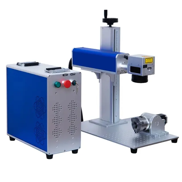
Pulsed fiber systems are a common starting point for metallic implant-marking trials. The rotary shown is relevant when cylindrical geometry needs controlled presentation; it does not mean every implant project requires a rotary axis. Final optics, positioning and workstation features are resolved later from the accepted sample result and production requirements.
What the first laser trial should decide
The first trial should answer a narrow question: which source family can produce the required mark on the actual material and surface within the accepted thermal/surface-impact window? Record the candidate source, pulse behavior and process window, then carry the accepted result forward. Optics, fixture, vision, rotary, automation, verification and enclosure choices are finalized later from geometry, production and sample-test findings rather than being assumed at this stage.
Troubleshooting
Common Implant Laser Marking Failure Modes and Corrections
When an implant mark fails — unreadable micro code, low contrast, fading after processing, or visible surface damage — the correction depends on which part of the chain is responsible. The check order below is a practical starting point, not a guarantee of outcome.
| Failure | Check first | Correction direction |
|---|---|---|
| Micro code unreadable | Focus depth, cell size vs material response, scanning strategy | Re-check focus and field; evaluate beam quality and pulse settings on sample |
| Low contrast on metal | Pulse parameters, surface state, marking area cleanliness | Parameter window review; confirm surface treatment sequence |
| Mark fades after passivation or sterilization | Mark depth vs surface-only contrast; downstream step conditions | Adjust mechanism (oxidation vs removal) and re-validate through the full loop |
| Heat halo, oxide spread or coating damage | Heat input, scanning strategy, coating/surface sensitivity | Lower thermal input, tune pulse window, evaluate UV or MOPA route |
| Batch-to-batch variation | Fixture repeatability, parameter file control, material batch variation | Locked parameter files, datum-checked fixtures, documented setup |
Production Workflow
How an Accepted Implant Mark Moves Into Production
Production is more than repeating the laser scan. The workstation has to present the correct part, call the correct controlled data and parameter set, place the mark consistently, verify the result, separate rejects and retain the required process record. The level of automation depends on batch size, changeover frequency and traceability requirements.
- Select the controlled job: load the approved device/part record, mark content and validated parameter recipe; prevent the wrong program from being used for a different material or surface state.
- Load and present the part: manual loading, tray/nest loading, rotary presentation or automatic feeding should place the correct surface in a known orientation without damaging critical areas.
- Position and focus: use fixture datums, rotary indexing, vision or height-control functions as required by the geometry; vision corrects position/orientation, but does not by itself solve uncontrolled height or curvature.
- Mark with the validated process window: execute the approved source/optics/parameter combination rather than re-tuning operators toward a visually darker mark.
- Verify the result: inspect human-readable content and use the defined reader/verifier method for machine-readable codes; apply the same acceptance rule used during sample validation.
- Handle pass / reject: prevent failed or unreadable parts from continuing as accepted production and define the rework or disposition path within the manufacturer’s quality process.
- Log and control the record: retain the required job, code, verification or batch information and keep parameter files/changeover settings under control.
| Production mode | Main risk to control | System features to evaluate |
|---|---|---|
| Low-volume / specification-heavy batches | Wrong setup or recipe during frequent changeover | Controlled recipes, dedicated/adjustable fixture, operator verification |
| Repeat batches of the same component | Fixture drift and batch-to-batch variation | Dedicated datum fixture, saved parameters, repeatable focus and verification |
| Variable presentation | Incorrect position or rotation | Vision positioning where the geometry and focal height permit it |
| Cylindrical marking | Angular position and circumference focus | Rotary axis, indexed motion and part-specific clamping |
| High-volume standardized production | Loading consistency, verification bottleneck and reject control | Automatic loading / multi-station workflow, verification and data integration after process validation |
When validated demand moves beyond manual or simple fixture loading, evaluate whether indexed handling or an automatic marking cell is justified by the real batch size, changeover pattern, verification load and reject-control requirement.
Sample Acceptance
How to Accept an Implant Marking Sample Before Equipment Commitment
The mark is not validated when it looks readable on the bench. For an implant component, validation means checking it on the actual surface state after the downstream steps that really apply to that device — such as cleaning, passivation and the specified sterilization process where applicable — and against the defined verification or acceptance criteria.
The validation loop
- Define the sample: the same material grade, surface finish and geometry as production; state which batch or surface state the sample represents.
- Mark with candidate parameters: record the parameter file and mark content exactly as it will be used.
- Run the downstream steps: reproduce the cleaning, passivation, coating or sterilization process that actually applies to the device. Do not substitute a generic steam cycle for the manufacturer’s specified process.
- Re-verify: check contrast, symbol grade and legibility with the same method production will use — a verifier for graded codes, not only visual inspection.
- Review the surface: confirm the mark did not damage the material, coatings or critical surfaces, with the material engineer’s acceptance.
- Freeze and document: lock the parameter file, acceptance criteria and sample reference for production and for the manufacturer’s required qualification or validation documentation.
Sample acceptance checklist
| Item | What to record |
|---|---|
| Sample identity | Material grade, surface state, geometry, batch reference |
| Mark content | Text, Data Matrix content, size, placement on the part |
| Readability | Symbol grade / verification result, reading conditions (lighting, verifier model) |
| Downstream survival | Result after the applicable cleaning, passivation, coating and sterilization steps tested |
| Surface review | Visual and, where relevant, dimensional / surface-state check by the material engineer |
| Process record | Parameter file, machine setup, sample photos, sign-off |
The purpose is to remove guesswork before equipment commitment: what survives on a test coupon under different conditions is not automatically what survives on the production part through the real processing chain. Verification and result logging connect to the traceability and data-integration solution; the UDI marking page details DPM grading.
Test Result → Machine Configuration
How Sample-Test Results Determine the Final Machine Configuration
The sample report should end with configuration consequences, not only a photo of the mark. Once a candidate process has passed the agreed acceptance criteria, the result is used to freeze the laser route, optics, positioning method, fixture, verification workflow and the level of production automation that the application actually needs.
| Sample-test finding | Configuration consequence |
|---|---|
| Q-switched fiber achieves the required readability and surface acceptance with a stable process window | Keep the fiber route and freeze the validated parameter window; select power class around the demonstrated process and required cycle, not by “more power is better.” |
| Wider pulse control gives a materially better contrast / thermal window on the actual metal surface | Prefer a MOPA fiber configuration and preserve the validated pulse-control range in the production recipe. |
| The required result cannot be achieved within the allowed thermal/surface-impact window | Evaluate a lower-thermal-input route such as UV where technically appropriate, or revisit the mark mechanism/specification rather than increasing power blindly. |
| The required micro code only verifies reliably with a smaller field / tighter optical setup | Select the field lens, working distance and marking field around the accepted code size and focus tolerance. |
| Cylindrical presentation is necessary for the approved mark location | Add the rotary axis and a chuck/fixture that holds the part concentrically without damaging critical surfaces. |
| Curvature or height variation exceeds the usable focal tolerance | Evaluate a 3D/dynamic-focus or multi-position approach; do not treat vision alone as a height-correction solution. |
| Part position/orientation varies but focal height is controlled | Add vision positioning and define the acceptable presentation window. |
| Fixture repeatability, not laser response, causes variation | Redesign the datum, clamping or part-presentation method before adding laser capability. |
| Manual loading meets quality but not the required production flow | Evaluate multi-part fixturing, indexed handling or automatic loading based on the real batch size and changeover pattern. |
| Production requires graded-code verification, pass/reject control or retained traceability records | Add the appropriate verifier/reader, software/data interface and reject/logging workflow to the marking cell. |
| The material/process assessment requires controlled fumes or particulates | Include enclosure, extraction or ventilation appropriate to the configured process and complete workstation safety assessment. |
The final machine is the result of the accepted process. A useful quotation should therefore be based on the actual sample result plus geometry, handling, production volume, verification/data and safety requirements — not on laser wattage alone.
Once those requirements are frozen, use the laser marking machines category to route the equipment choice: fiber machines for validated metal routes, UV machines where the accepted process requires that source family, and vision or enclosed machine variants when the validated positioning or safety requirements call for them.
Safety & Environment
Safety and Processing Environment
Implant marking workstations are reviewed as a complete system: laser access control, enclosure and interlock options where production requires them, extraction for the fume and particulates that metal and polymer marking produce, and eye protection appropriate to the wavelength in use. A machine being enclosed does not by itself make it a Class 1 product; the safety classification follows the complete configured system and its accessible radiation conditions. Polymer and coated materials need fume control as part of the process design. On polished titanium and stainless components, direct and reflected 1064 nm radiation must also be included in the workstation review — guarding, viewing windows and eye protection follow that assessment. Detailed machine-level safety configuration belongs to the enclosed laser marking machines product page.
Sources
Sources for Implant Marking and UDI Context
The following sources support the regulatory and quality context referenced above. Regulations and standards are revised over time; verify the current version and its applicability for the target market before relying on them.
- U.S. Food and Drug Administration — Unique Device Identification System, 21 CFR Part 801 and Part 830 — regulation (official text; verify current edition) — fda.gov UDI system
- European Commission / EUR-Lex — Regulation (EU) 2017/745 on medical devices (MDR) — regulation (verify current consolidated text) — EUR-Lex MDR 2017/745
- ISO/IEC 15415:2024 — Automatic identification and data capture techniques — bar code symbol print quality test specification for two-dimensional symbols — standard (obtain from ISO or a national standards body)
- ISO/IEC 29158:2025 — Automatic identification and data capture techniques — bar code symbol quality test specification for Direct Part Mark (DPM) — standard (obtain from ISO or a national standards body)
- ISO 13485 — Medical devices — Quality management systems — requirements for regulatory purposes — standard (obtain current edition from ISO or a national standards body)
- GS1 — UDI guidelines and Data Matrix usage in healthcare — industry guideline (verify current version) — gs1.org healthcare
This page provides engineering information only. It does not replace a regulatory review, a risk assessment or the judgment of the manufacturer’s responsible personnel for a specific device.
FAQ
Medical Implant Laser Marking FAQ
Can implant components be laser-marked, and what determines whether it works?
Yes, laser marking is a recognized route for permanent identifiers on implant components. Whether it works for a specific part depends on the material and surface state, the available marking area, the heat the material can accept, and the post-processing the mark must survive. Those four constraints are evaluated together, normally with a sample test.
How small can a Data Matrix code be on a small titanium component?
There is no single safe minimum size that applies to every titanium implant. The practical limit depends on the available marking area, Data Matrix module size, material and surface response, beam quality, focus and part geometry. Confirm the smallest usable code on the actual component and accept it only when the planned production verification method can grade or read it reliably.
Will the mark survive passivation and sterilization?
It can, but that is a validation result, not an assumption. Check the mark after the actual downstream process specified for the device — for example cleaning, passivation and the applicable sterilization method — using the same verification method production will use. Medical devices can use different sterilization routes, so a generic steam-temperature range should not be treated as the default validation condition. Marks made by different mechanisms, such as surface oxidation and material removal, can behave differently through those steps.
Can laser marking affect implant strength or corrosion behavior?
Excessive or poorly controlled heat input can raise questions about surface condition, fatigue or corrosion on load-bearing implants. Whether a specific mark is acceptable is a device-level engineering judgment involving the material engineer. The marking setup’s job is to use the minimum heat input that achieves the required readable mark and to provide samples for that review.
Should we choose fiber, MOPA or UV?
The source is chosen for the material, mark size and heat budget. Q-switched fiber is a common starting point for annealed metal marks; MOPA adds wider pulse control for contrast tuning; UV provides lower thermal input, which matters on heat-sensitive materials and some polymers. The choice is confirmed on a sample with the actual surface state.
What do we need to prepare for a marking evaluation?
Provide the material grade and surface finish, part drawing or sample, required mark content and available area, target result or acceptance criterion, loading/orientation condition, downstream processing steps, production volume, and any data or verification requirements. Those inputs are enough to define the first laser route, sample-test plan and the configuration questions the test must resolve.
Start the Evaluation
Plan an Implant Component Marking Evaluation
If you are evaluating laser marking for an implant component, send the part’s material and surface state, a drawing or sample, the required mark content and available area, the target acceptance result, loading/orientation condition, downstream processing steps, production volume, and any verification or data requirements. The sample test can then be accepted against defined criteria and translated into the laser source, optics, fixture/positioning, verification and automation configuration needed before equipment commitment.
Standard equipment and clear specifications can be quoted directly; vision, rotary, automation or data-integration projects are reviewed as custom configurations.