
Coated metal material guide
Painted Metal Laser Marking
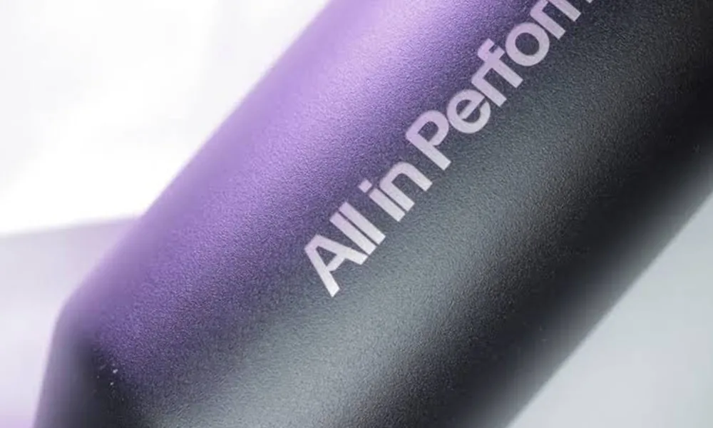
Yes, painted metal can be laser marked, but the result depends on the complete coating stack. Paint chemistry, coating thickness, cure, pigment, primer, substrate reflectivity and pretreatment decide whether the laser changes the topcoat, selectively removes it to a defined layer or damages the edge.
01 · Feasibility
Can Painted Metal Be Laser Marked?
Yes. Painted steel, painted aluminum and other coated metal parts can be laser marked when the laser interaction is matched to the actual paint/primer/substrate stack. The first decision is whether the process should remove a coating layer or create a visible change while keeping the coating functionally closed.
Remove paint to a defined layer
Use the laser to selectively open the topcoat so a primer or metal layer creates the required contrast. This route must control the stopping layer, edge width, residue, adhesion around the mark and the condition of any newly exposed metal.
Change the coating without fully exposing metal
Use the laser to change color, reflectance or texture inside the paint when the coating needs to remain closed. The acceptance check should still look for halo, thinning, pinholes, blistering, gloss change and durability after cleaning or handling.
02 · Surface conditions
The finished coating system controls the process window
“Painted steel” or “painted aluminum” is not enough to select a machine. Record the actual topcoat, primer, cure, thickness, gloss, substrate and pretreatment because each layer changes absorption, heat flow, removal selectivity and the condition of the exposed edge.
Topcoat chemistry and pigment
Resin, pigment, filler, gloss and supplier formulation influence absorption, contrast, plume and residue. A color name is a screening clue, not a process specification.
Thickness, cure and adhesion
Coating thickness variation, under-cure, over-cure, rework and adhesion change the threshold for removal and the risk of lifted or feathered edges.
Primer and metal below
Primer, pretreatment, alloy, surface roughness, reflectivity and corrosion protection determine what may be exposed and how quickly heat spreads after the paint opens.
| Input | What it can change | Minimum record | Why it matters |
|---|---|---|---|
| Topcoat / pigment | Absorption, visible contrast, plume and residue | Supplier, product, color, gloss and SDS when available | Two paints with the same color can require different screening. |
| Thickness and cure | Removal threshold, edge width and undercut | Nominal thickness, cure route, lot variation and rework state | A single center-point setting may fail at the thick or under-cured edge. |
| Primer / pretreatment | Adhesion, corrosion barrier and stopping response | Primer type, pretreatment, permitted exposure and post-mark protection | “Metal exposed” is not automatically an acceptable result. |
| Substrate alloy and finish | Reflectivity, heat flow, discoloration and corrosion behavior | Alloy/grade, surface roughness, polished or blasted state | Substrate condition determines the quality of the revealed layer. |
03 · Products and marking purpose
Where Are Painted Metal Parts Used and Why Are They Marked?
Painted metal parts are used where the coating provides appearance, corrosion protection, environmental protection or a finished customer-facing surface. Laser marking is usually considered when the information must be permanent, precisely positioned or integrated into a traceability workflow without adding a separate label.
Equipment enclosures and control panels
Painted steel or aluminum housings may need model identification, control legends, warning symbols, scales or serial information. The challenge is producing clear information without damaging the finished surface around the mark.
Automotive and EV components
Painted brackets, covers, housings and fabricated parts may require part identification or traceability through assembly and service. The acceptable result depends on whether exposing primer or metal is allowed in the marked area.
Appliances, tools and durable goods
Coated panels, handles, housings and frames may carry branding, model information, operating symbols or permanent identification. Appearance consistency is often as important as basic readability.
Fabricated sheet-metal parts and cabinets
Painted panels, electrical cabinets, machine guards and general fabricated parts may need assembly IDs, orientation marks or permanent asset information. Large areas and formed geometry can make positioning and focus control part of the machine decision.
04 · Mark content
What Is Usually Marked on Painted Metal?
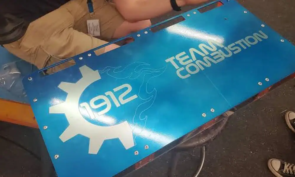
The content determines feature size, contrast requirement, positioning tolerance and verification method. A large logo, a small Data Matrix code and a fine control-panel legend may all use the same painted substrate but need different optics, process windows and inspection rules.
Identification
Part numbers, serial numbers, batch or lot codes, asset IDs and model information used for manufacturing, inventory or service.
Traceability codes
Data Matrix, QR codes and barcodes when the application requires machine-readable identification. Code size, quiet zone, contrast and verification method should be defined before testing.
Functional and safety information
Scales, symbols, control-panel legends, orientation marks, warnings and operating information where readability and position relative to controls or features matter.
Branding and product information
Logos, product names and permanent customer-facing information where edge quality, surface appearance and consistency between parts can be primary acceptance criteria.
05 · Define the result
What Should an Acceptable Painted-Metal Mark Look Like?
Once feasibility is established, define acceptance by the stopping layer, contrast, edge quality, coating integrity, substrate condition and durability. A visible mark is only useful if those limits are met on the real finished part.
Selective coating ablation and substrate exposure
Remove the paint to a defined boundary so the primer or metal creates the required contrast. Inspect coating removal completeness, exposed-layer condition, edge position, undercut, residue, adhesion around the mark and any corrosion-protection consequence.
- Target stopping layer is explicit.
- Edge is clean without feathering or lift.
- Substrate is not overheated or discolored beyond the limit.
- Cleaning and downstream protection are included in the test.
Controlled color or texture change inside the paint
Change reflectance, color or texture while keeping the coating closed. The result still needs inspection for gloss shift, halo, roughness, pinholes, local thinning, adhesion change and durability under the finished use condition.
- Contrast remains readable under actual lighting.
- Coating remains functionally intact where required.
- No hidden edge damage or blistering develops after cleaning.
- Wear, chemical and temperature checks match the part requirement.
Approved coating result
Artwork, contrast or removal area, edge location and exposed-layer condition meet the drawing and agreed inspection rule.
Readable but not automatically acceptable
Halo, gloss change, roughness, residue, edge drift, local thinning or uncertain primer exposure needs review.
Functional or protection damage
Unintended substrate damage, delamination, corrosion-barrier loss, burn, blistering or uncontrolled exposed area blocks approval.
06 · Geometry and access
How Do Part Shape, Thickness and Size Change the Process?
The coating stack controls how the surface reacts, but part geometry controls whether the laser can keep the same focus, spot condition and position across the real mark area. Evaluate the production part, not only a flat coated coupon.
Flat sheet and flat panels
Flat areas are the simplest case for keeping focus and removal depth consistent. Even here, coating thickness and field-position variation should be checked across the real marking area.
Curved or formed housings
Height changes alter focus and effective energy density across the mark. Small curvature may fit within the usable focus tolerance; larger height variation can require repositioning, 3D focus compensation or a different marking strategy.
Cylindrical parts
A narrow mark may fit on the visible tangent area, while a mark that wraps around the circumference can require rotary motion or coordinated positioning to keep geometry and focus controlled.
Thin sheet metal
The laser mainly interacts with the coating, but repeated passes or excessive heat can still discolor the substrate or contribute to local distortion. Thin parts should be tested in their real supported condition.
Large panels and enclosures
Large parts shift the problem from source power alone to field size, part access, focus consistency, fixture repeatability, motion axes and sometimes vision-assisted positioning.
Edges, bends, holes and recessed areas
Paint thickness and spray coverage can differ near formed features, while access angle and local heat flow also change. Include critical edge and corner locations in the sample matrix instead of validating only the center of a flat face.
07 · Laser route selection
Which Laser Route Should You Test First?
For many opaque painted-metal parts where controlled coating removal is the goal, Q-switched fiber and MOPA fiber are logical first comparison routes. UV becomes more relevant when fine features, coating response or heat sensitivity require a narrower interaction, while CO2 or another wavelength may be useful for selected coating chemistries. The final choice still depends on the exact coating stack, stopping layer and acceptance criteria.
| Direction | Where it may fit | Main boundary | Evidence needed |
|---|---|---|---|
| Fiber / Q-switched 1064 nm | Common first screening direction for opaque paint removal or contrast on selected metal parts. | Can heat the exposed metal, widen the edge, discolor the substrate or couple unpredictably through pigment and primer. | Selective removal, substrate condition, edge quality, residue and repeatability across coating variation. |
| MOPA 1064 nm | Compare when pulse-width and repetition-rate control may help map coating removal against substrate heat on the exact stack. | MOPA is not automatically lower-damage or better; pulse energy, overlap, focus and heat accumulation can still lift paint or damage the exposed layer. | Side-by-side edge width, stopping-layer control, substrate condition, residue and a repeatable window across coating variation. |
| UV laser | Fine features or coatings that absorb usefully at UV wavelengths; a lower heat-affected result is a test question, not a default assumption. | UV is not damage-free; excessive fluence, poor focus or a mismatched chemistry can still cause lift, residue or a weak edge. | Feature fidelity, coating integrity, plume, edge width and stable window on actual production paint. |
| CO2 laser | Conditional interaction with organic topcoats, larger decorative removal or projects where the paint responds more strongly at CO2 wavelengths. | Strong surface interaction can increase heat-affected area, roughness, fumes or substrate exposure. | Removal uniformity, edge burn, plume extraction, substrate heat and downstream appearance. |
| Green or other project route | Special coating/substrate combinations where absorption or a fine-feature requirement justifies a comparative trial. | Availability and optical configuration must be confirmed; the wavelength should not be selected from paint color alone. | Side-by-side sample evidence, feature quality, stopping-layer control and production repeatability. |
08 · Risks and failure modes
Read the failure mode before increasing energy
Low contrast does not automatically mean “add power.” The visible defect should tell you whether to check absorption, focus, scan strategy, layer identity, fixture stress or the source direction.
Burned or widened edge
Darkened substrate, a broad heat-affected zone or a soft edge can indicate excessive local heat, multiple passes, poor focus or a substrate that couples strongly after the paint opens.
Paint lift and delamination
Lifted edges, blistering or a feathered boundary may point to coating adhesion, under-cure, heat accumulation or an unsuitable removal mechanism. Inspect after cleaning and handling.
Residue and redeposition
Residue can come from topcoat, primer, contamination or incomplete extraction. Separate “clean center” from “clean edge” and record the cleaning process that the finished part will use.
Uneven contrast or exposure
Patchy marks may follow thickness variation, pigment distribution, surface curvature, field position or focus drift. Compare representative lots and positions before changing the nominal power.
| Observed symptom | Check next | Decision direction |
|---|---|---|
| Edge burn or substrate discoloration | Energy density, passes, focus, scan speed, substrate alloy and exposed-area dwell | Narrow the interaction, change the route or reject the edge condition. |
| Paint lift, blister or feathered edge | Coating cure, adhesion, thickness, heat accumulation and cleaning | Requalify the layer system before treating the defect as cosmetic. |
| Residue or redeposition | Extraction point, plume path, coating chemistry, contamination and post-cleaning | Adjust extraction/cleaning and inspect optics and fixtures for buildup. |
| Patchy or unstable contrast | Lot variation, pigment, gloss, curvature, field position and focus tolerance | Expand the sample matrix or choose a route with a wider usable window. |
09 · Sample validation
Build a sample matrix that exposes coating and edge variation
One attractive photograph or one easy coupon does not prove a production window. The test should use the finished coating stack, critical mark positions and the inspection method that will govern release.
Freeze the target mechanism
Separate selective ablation from color/texture change. Provide artwork, smallest feature, edge tolerance and the allowed stopping layer.
Group the finished surfaces
Record topcoat, primer, supplier, color, gloss, cure, thickness, substrate, pretreatment and relevant lot variation.
Compare a process window
Hold lighting, cleaning and inspection constant while comparing repeated marks across representative lots, positions and focus variation.
Translate to production
Add fixture repeatability, height/position tolerance, extraction, verification, data handling and full cycle time before sizing the machine.

Route recommendation
Conditional source-family direction tied to the submitted coating stack, stopping layer and feature size.
Evidence record
Marked-sample observations for contrast, edge quality, exposed layer, residue and repeatability, with open risks clearly separated.
Configuration inputs
Confirmed requirements for optics, fixture, extraction, inspection, data handling and the next machine-review step.
For a useful inquiry: attach finished parts or representative coupons, coating and primer information, a drawing or mark artwork, smallest feature, allowed exposure, cleaning method, target cycle time and the inspection or durability requirement. A quote request starts the review; it does not replace finished-stack validation.
| Record | Minimum detail | Why |
|---|---|---|
| Surface identity | Topcoat, primer, supplier, color, gloss, cure, thickness, substrate and pretreatment | Prevents different surface stacks being treated as one material. |
| Target mechanism | Selective ablation or closed-coating color/texture change; artwork and smallest feature | Defines the interaction and the stopping boundary. |
| Edge and substrate | Edge width, undercut, lift, exposed-layer condition, discoloration and residue limit | Separates readable from controlled and durable. |
| Post-process checks | Cleaning, adhesion, wear, chemical, thermal and corrosion-related checks when required | Confirms that the mark does not remove the protection the part needs. |
| Production inputs | Part dimensions, field, focus variation, fixture, vision, data, loading and full cycle target | Routes the material result into a complete machine configuration. |
10 · Machine configuration and safety
The approved paint result is only one part of the complete system
Once the material route is credible, the machine review matches the accepted interaction to optics, fixture, enclosure, extraction, control and production workflow. Paint removal can create fumes and fine particles, so the process point and filter plan belong in the review.
Source and optics
Match wavelength, pulse behavior, spot size, field and focus to the smallest feature, coating thickness and edge tolerance. A larger field is not automatically the best choice for edge quality.
Fixture and part access
Support flatness, curvature, orientation and edge distance without scratching or stressing the coating. Rotary or height compensation may be required for varying surfaces.
Extraction and housekeeping
Review coating information or SDS when available, local capture, filtration, residue handling, optics cleanliness and buildup on fixtures. The actual plume determines the extraction plan.
Data and verification
Variable data, vision positioning, code verification, reject handling and line integration belong to the configured application. Use the relevant vision solution after material feasibility is approved.
11 · Frequently asked questions
Painted-metal laser marking questions
Can a laser remove paint and leave a clean metal mark?
It can be evaluated on the exact paint/primer/substrate stack. Approval requires more than visible removal: inspect edge position, undercut, residue, substrate heat/discoloration, adhesion around the mark and any corrosion-protection consequence.
Is a 1064 nm fiber source always the best choice for painted metal?
No. Q-switched fiber and MOPA sources should be compared by pulse behavior, spot, overlap and heat accumulation on the exact coating stack. UV, CO2 or another route may be more useful for a particular feature size, stopping layer or heat limit. Sample evidence should decide.
Can painted aluminum and painted steel share one setting?
Not automatically. Substrate reflectivity, heat flow, primer, paint chemistry and thickness can change the process window. Treat alloy and finished surface as separate qualification groups unless testing proves a shared window.
How do I judge edge quality?
Define edge width, feathering, undercut, lift, residue, halo, substrate discoloration and the inspection method before testing. Check the critical mark location and the post-cleaning condition, not only an enlarged center photograph.
Do painted-metal marks always need to expose bare metal?
No. Some applications intentionally remove the topcoat to a primer or metal layer, while others need a visible color or texture change without fully opening the coating. The acceptable stopping layer should be defined before laser trials because exposure can change appearance, adhesion and corrosion protection.
What should I send for a painted-metal sample test?
Send finished production parts or representative coupons with topcoat/primer information, color and gloss, cure and thickness, substrate and pretreatment, artwork, smallest feature, target mechanism, allowed exposure, cleaning method and production context.