
Consumer Products · Personalization · Mixed Phone-Case Surfaces
Phone Case Laser Marking
A reliable phone-case marking process starts with the actual marking layer and case construction, then works through the required appearance, mark zone, product geometry, production mix and sample result. The final machine should be chosen from those test results—not from the words “plastic case,” “leather case” or laser power alone.
Product / Construction Scope
What Types of Phone Cases Are Being Marked?
Typical workpieces include slim rigid shells, flexible protective cases, clear cases, rugged or hybrid cases, leather or folio-style cases, and magnetic-ring cases. Start by identifying the product form and the visible marking layer, then note any backing, flexibility or internal insert under the intended mark zone.
PC and Other Rigid Plastic Cases
Slim rigid shells commonly use PC or other rigid polymers. Note whether the marking face is flat, raised or recessed.
TPU, Silicone and Soft-Touch Cases
Flexible protective cases may use TPU, silicone or other soft polymers. Note whether the case deforms during normal loading.
Leather and PU Leather Cases
Leather, PU and folio-style cases may combine a visible skin, grain or coating with a backing layer. Identify the surface actually being marked.
Painted, Printed and Coated Cases
Painted, printed and coated cases use an added finish over the structural shell. Record the visible finish and the substrate beneath it when known.
Clear or Translucent Cases
Clear or translucent cases should be identified separately because tint, transparency and backside visibility are part of the product appearance.
Cases with Magnetic Rings, Inserts or Multiple Layers
Rugged, magnetic-ring and multi-layer cases can combine a rigid shell, soft bumper, liner, adhesive, metal ring or decorative insert. Map the parts below the intended mark zone.
Application Purpose
Why Are Phone Cases Laser Marked?
The reason for marking determines the artwork, inspection method and production workflow. Decorative personalization and production identification can use the same marking station, but they do not have the same acceptance criteria.
Personalization and Branding
Names, monograms, logos, illustrations and short-run graphics support customized orders and branded product presentation. Frequent artwork changes make file control and positioning part of the production requirement.
Product and Model Identification
Model references, edition information and approved product text help separate variants. The required content and location should follow the product specification rather than a generic layout.
Traceability and Order Control
Batch, date, order or serialized data can connect a marked case to a production or fulfillment record. When information changes from part to part, duplicate prevention and correct file/data selection become part of process control.
Marking Content
What Is Usually Marked on a Phone Case?
Separate the purpose of the mark from the actual content. A production test should use the real artwork size and the smallest features that will appear in normal orders.
| Content type | Examples | What to reproduce in testing |
|---|---|---|
| Personalized text | Name, initials, monogram, short message | Smallest character, longest name, intended font and real placement zone. |
| Brand graphics | Logo, icon, illustration, decorative pattern | Fine lines, filled areas, edge definition and the largest normal graphic. |
| Product identification | Model, edition, internal part or product reference | Actual text size, orientation and required consistency across SKUs. |
| Variable data | Batch, date, order, serial, QR or Data Matrix when required | Data source, update rule, duplicate prevention and readable feature size. |
Result Variables
What Determines the Phone Case Marking Result?
The product name does not determine the mark. The process window—the stable range of settings that repeatedly gives an acceptable result—is set by the layer hit by the laser, its formulation and finish, the geometry under that layer, the artwork and the production requirement.
1. Marking Layer
Molded resin, paint, soft-touch coating, printed decoration, leather finish and PU skin are different laser targets even when they are part of the same phone-case assembly.
2. Color and Formulation
Pigments, fillers, additives and supplier or batch variation can change absorption, contrast and the threshold between a clean mark and unwanted surface damage.
3. Surface Finish
Gloss, matte texture, grain, molded texture and coating consistency change how the mark looks and how easily edge defects or heat effects can be seen.
4. Geometry and Wall Construction
Curvature, wall thickness, camera islands, recesses, flexible walls and internal layers influence focus, fixture support and the allowable thermal window.
5. Artwork and Mark Area
Fine text, dense fills, large graphics and edge proximity can require different scan strategy and process margin. Test the hardest artwork, not only a large simple logo.
6. Production Requirement
Quantity, required production pace, SKU mix, color mix, changeover frequency, manual or automated loading and inspection requirements determine whether a sample result can be repeated efficiently.
| Case condition | Typical result to screen | Main risk to check |
|---|---|---|
| Rigid molded plastic | High-contrast color change, controlled surface texture change or shallow mark, depending on formulation and target appearance. | Weak contrast, glossy halo, melting, rough edge or color-to-color variation. |
| TPU / silicone / flexible surface | Readable contrast with limited distortion and a controlled tactile/cosmetic change. | Melting, tacky or glossy areas, part deformation and positioning shift during loading. |
| Leather / PU leather | Tonal contrast, darkening, controlled surface engraving or texture change that matches the cosmetic requirement. | Burning, excessive edge darkening, odor/residue, coating damage or uneven response across grain. |
| Painted / coated rigid case | Controlled top-layer color change or selective removal while keeping the substrate and adjacent finish inside the cosmetic limit. | Uneven breakthrough, exposed substrate damage, ragged edge or coating delamination. |
| Clear / translucent case | Visible haze, frosting, whitening or subtle contrast where acceptable under agreed lighting. | Low visibility, unwanted clouding, backside appearance change or stress/thermal damage. |
| Hybrid or insert-equipped case | Modify only the intended visible layer while protecting the layers and components below it. | Heat transfer to adhesive/lining/insert, local distortion or inconsistent response over changing construction. |
Target Result
What Should an Acceptable Phone Case Mark Achieve?
Define the required result before choosing the laser. “A visible logo” is not enough if the finished case also has to meet cosmetic, durability and repeatability requirements.
Use the Actual Case to Approve the Final Effect
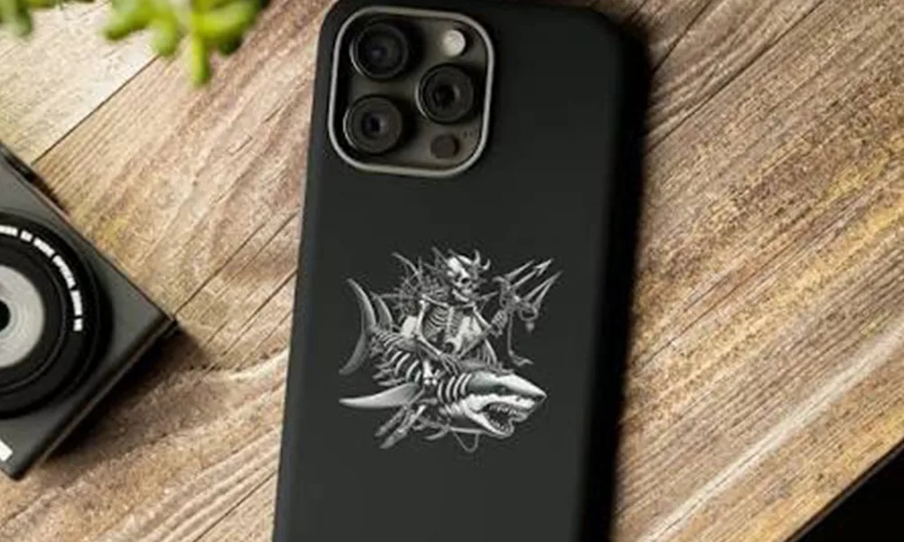
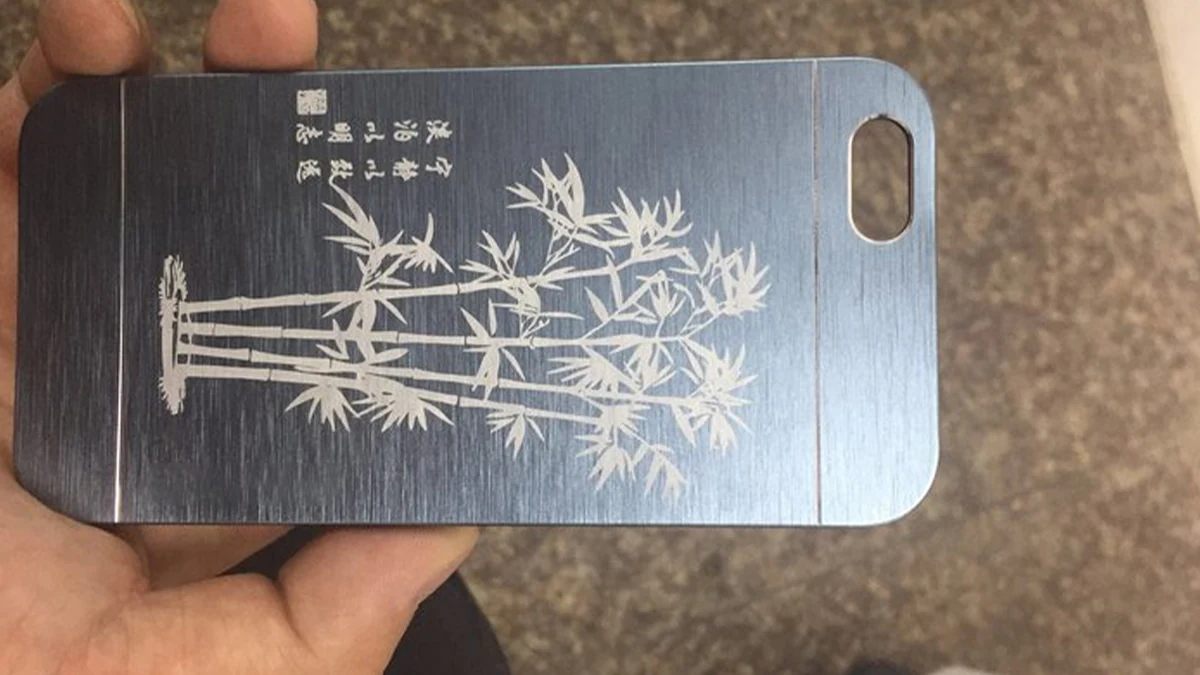
A sample photo can show an achievable appearance on that photographed workpiece, but it should not be generalized across different phone-case materials, coatings or colors.
For a production recommendation, the useful evidence is a marked sample from the customer’s actual construction, together with the mark zone, artwork size, surface condition and acceptance result.
For mixed case families: qualify at least the variants most likely to change the process window—different surface layer, color, thickness, texture, curvature or internal construction.
Geometry & Loading
How Do Camera Islands, Magnetic Inserts, Thin Walls and Loading Affect Marking?
Phone cases are rarely one uninterrupted flat sheet. Keep-out zones, height changes, flexible walls and hidden layers can affect focus, cosmetic risk and repeatable positioning.
Raised Camera Islands
Record the height difference between the main back surface and the camera lip. A mark close to a raised feature can lose focus or create clearance problems even when the center of the case marks well.
MagSafe Rings and Other Inserts
Map magnetic rings, metal plates, adhesive and decorative inserts below the surface. They may change local construction and should be included when defining thermal limits and keep-out zones.
Thin-Wall Areas
Thin sections need extra attention for local melting, distortion, backside appearance and heat transfer into lining, adhesive or another layer.
Cosmetic Keep-Out Zones
Protect camera openings, glossy decorative zones, seams, transparent windows, edge radii, logos that must remain untouched and any surface controlled by the product drawing.
Flexible-Case Loading
A soft case can stretch, bow or shift when placed by hand. A nest should support the part without deforming the marking surface or moving the fixture datum (the locating reference used to position the artwork).
Locating Reference, Focus and Clearance
Define what feature locates the case, where the focus reference is taken and how much Z/workstation clearance the fixture needs across the complete SKU range.
First-Test Laser Route
Which Laser Route Should Be Tested First?
This is a screening matrix, not a final machine-selection table. Start with the actual marking layer and required effect, then compare the route that is most likely to meet the cosmetic and thermal limit on the real case.
| Workpiece condition | First route to evaluate | What the sample must prove |
|---|---|---|
| Heat-sensitive molded plastic or fine cosmetic artwork | UV is often worth an early comparison when minimizing visible thermal change is important. | Contrast or surface change, fine-edge quality, distortion and repeatability across colors/batches. |
| Plastic known to respond to near-infrared marking or laser additives | Compare fiber / MOPA fiber with UV according to the target appearance and thermal margin. | Required contrast without unacceptable melting, gloss change or surrounding heat effect. |
| Leather or many PU / organic-surface constructions | CO₂ is a practical starting evaluation; compare another source only when the construction or cosmetic target justifies it. | Tonal change or engraving appearance, edge quality, residue/odor control and effect on the finish/backing. |
| Painted or coated rigid shell | Choose the first route from the intended mechanism: color change, top-layer modification or controlled removal. Fiber/MOPA, UV or CO₂ may enter the comparison depending on the coating and substrate. | Modify only the intended layer, keep the boundary clean and protect the substrate and adjacent finish. |
| Rigid metal shell or metal decorative area | Fiber / MOPA fiber is normally the first family to screen for direct metal marking or controlled surface response. | Appearance, edge quality, heat effect, coating/anodizing condition and cosmetic acceptance. |
| Unknown, clear, multilayer or insert-equipped construction | Do not choose from the product name alone. Run a small source comparison on the real workpiece after identifying the visible layer and thermal/depth limit. | Which route creates the required effect with the widest usable process margin and least collateral change. |
Important: power alone is not a selection rule. Wavelength/source family, pulse behavior, spot/field choice, scan strategy, geometry and the real material response all influence the usable window.
Failure Diagnosis
What Can Go Wrong During Phone Case Laser Marking?
Do not treat every poor result as “not enough power.” The visible failure usually points to a smaller set of material, focus, geometry, fixture or process-window causes that can be checked systematically.
| Observed failure | Likely causes to investigate | Check before changing the machine |
|---|---|---|
| Weak or inconsistent contrast | Resin/coating formulation, pigment, supplier or batch variation, unsuitable source or process window. | Compare known-good and failed variants with the same artwork and fixture; record material/color/batch. |
| Melted edge or glossy halo | Excess thermal input, overlapping energy, slow scan, unsuitable pulse/source or poor focus. | Reduce the thermal load systematically and compare another route if the acceptable window remains too narrow. |
| Uneven mark across one case | Curvature, height change, texture variation, inconsistent focus or unsupported flexible surface. | Measure/inspect the mark-plane variation and repeat with controlled support and focus reference. |
| Logo position shifts between parts | Loose nest, flexible case deformation, inconsistent datum, SKU mismatch or loading variation. | Check fixture repeatability before changing laser parameters; repeat the same artwork on multiple loaded parts. |
| Coating breaks through unevenly | Coating thickness variation, aggressive removal, underlying surface variation or wrong mechanism. | Inspect the transition edge and substrate; test a smaller process matrix rather than simply adding passes. |
| Backside / insert area changes | Thin wall, adhesive, lining or internal insert below the mark; excessive local heat or depth. | Section/map the construction, define a stop limit and verify the backside after the same exposure used in production. |
| One color works and another fails | Pigment/additive response or different supplier/formulation. | Treat color/formulation as a separate sample family; do not transfer settings from appearance alone. |
| Fine text looks worse than the test logo | Artwork feature size, field/spot choice, scan strategy, focus or surface texture. | Retest with the smallest production text/line width instead of approving from a large graphic. |
Production Workflow
What Must the Production Phone Case Marking Workflow Include?
In high-mix personalization, the production risk is not only the laser exposure. Wrong SKU, wrong artwork, wrong customer data or inconsistent loading can create a failed order even when the mark itself is technically clean.
- LoadConfirm the correct model, color, construction and approved marking face.
- Job / DataLoad the correct artwork and variable data, then confirm the active job before marking.
- PositionSeat the case against the approved locating reference or positioning method without deforming the surface.
- Focus / ZoneConfirm the focus reference, camera-island clearance, keep-out zones and correct marking field for that SKU.
- MarkRun the qualified process window for the defined surface and variant.
- InspectCheck content, position, cosmetic appearance and any required machine-readable code before release.
- Reject / ReleaseApply the defined decision for wrong data, shifted marks, cosmetic defects or failed codes instead of relying on ad hoc judgment.
- ChangeoverSwitch model, color, artwork or recipe through a controlled changeover so the accepted process is preserved between short runs.
Sample Qualification
How Should Representative Phone Case Samples Be Qualified?
Qualification should reproduce the hard parts of the real order mix. Approving one convenient case color with one large logo is not enough when production includes different surfaces, thin walls, small text and frequent changeovers.
Representative sample rule: the sample set should include the variant most likely to fail—such as the thinnest wall, strongest curvature, lowest-contrast color, most appearance-sensitive finish or most difficult artwork—not only an average case.
Test Result → Machine Configuration
How Do Sample-Test Results Define the Final Machine Configuration?
The final configuration should be a direct response to what the sample test and production workflow proved. A clean mark is only one input; field size, focus, fixture, software, clearance, extraction and loading still have to match the real job.
Laser & Optics
Fixture & Positioning
Data & Production
Workstation & Environment
Configuration decision: laser source + process window + marking field + focus/Z strategy + fixture + positioning method + software/data + extraction + safety/workstation + loading/automation level should all trace back to the qualified phone-case samples and production requirement.
Discuss Your Phone Case Marking Requirement
Send the actual case construction, surface/finish, colors, artwork, mark zone, dimensions, internal inserts, model mix, batch pattern and acceptance criteria. Zhuorui Laser can use representative samples to compare the practical laser route and define the machine configuration from the test result.