
Fabric Pattern Laser Marking · Textile & Leather
Laser Mark Patterns on Fabric
CO₂ is usually the first laser route to evaluate for fabric pattern marking, but the usable process window depends on the fiber or blend, dye and finish, fabric construction, target appearance, pattern detail, workpiece handling, and required production rate. The final machine configuration should be based on an accepted sample result rather than the fabric name alone.
Application scope
Is This the Right Fabric Pattern Marking Application?
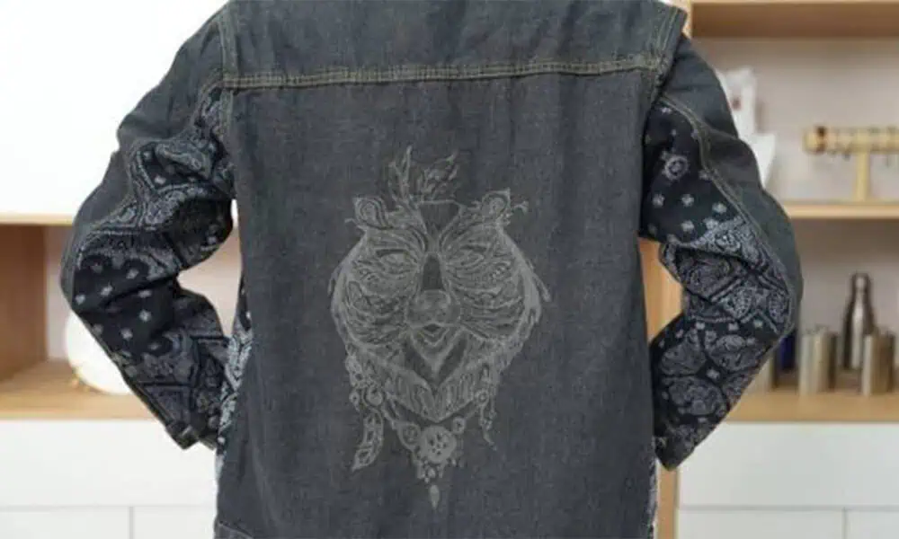
This page is for surface pattern, logo, decorative and controlled burn-off or tone-change work on textile products. Typical workpieces can include denim jacket backs and jeans panels, garment panels, fabric patches, decorative textile pieces and roll-fed fabric. The workpiece form matters because the same fabric behaves differently when it is flat, stretched, assembled into a garment or processed from a roll.
Cut Panels & Fabric Pieces
Suitable when the material can be held flat and the pattern must stay in a defined location.
Finished Garments
Seams, pockets, folds and local height changes make positioning and focus control part of the process.
Rolls & Web Material
Line speed, web tension and registration become as important as the laser recipe itself.
Coated or Laminated Textiles
The laser may modify or remove a surface layer rather than the underlying fiber, so coating response must be tested separately.
Application purpose
Why Use Laser Marking for Fabric Patterns?
The useful question is not simply whether a laser can affect fabric. It is whether a digital, non-contact process gives the required appearance and production flexibility without unacceptable damage to the textile.
Why manufacturers use it
- Change digital patterns without creating or changing mechanical tooling.
- Create localized logos, graphics, distressed areas or tone changes on selected zones.
- Run short batches or multiple designs with recipe and file changes rather than physical dies.
- Apply a non-contact process where mechanical pressure or direct printing is undesirable.
What is commonly marked
- Decorative patterns and repeated graphics.
- Brand logos, text and personalization.
- Controlled faded, distressed or burn-off effects.
- Fine lines, filled areas or mixed-detail artwork where the textile can reproduce them reliably.
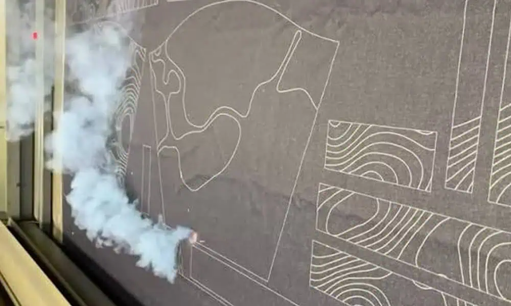
How the effect is created: CO₂ marking is primarily a thermal interaction. Depending on the textile, the laser can darken or carbonize natural fibers, melt or change the surface of synthetics, or modify a coating. The laser follows the digital scan path, but the final edge, contrast and fine detail still depend on the material and process window.
Result variables
What Determines the Result on Fabric?
Power and speed are only part of the answer. Start with the fiber chemistry and textile construction plus the mark requirement, then use process parameters to find a stable window.
Material & Surface
Fiber or blend, fabric weight, weave or knit, color, dye, coating, lamination, finish, thickness and batch variation all change how heat is absorbed and spreads.
Pattern Requirement
Pattern size, fine-line width, fill density, small text, desired shade and required edge definition change both the energy demand and the real cycle time.
Laser Process Window
Power, scan speed, pulse frequency where applicable, focus or controlled defocus, pass strategy and scan path determine how much heat reaches each area.
| Fabric group | Typical response to evaluate | Main risk | What to record in the test |
|---|---|---|---|
| Cotton, denim, linen | Darkening or carbonized surface effect; contrast varies with color, weight and finish | Scorch spread, yellow halo, loss of strength if over-heated | Shade, edge definition, fabric damage, wash response, cycle time |
| Polyester and blends | Surface melting, texture change or lighter/different tone depending on construction and dye | Over-melting, gloss change, stiffness, holes | Surface feel, distortion, edge quality, no burn-through, repeatability |
| Nylon, mesh, sheer fabrics | Highly construction-dependent; narrow process window on lightweight material | Shrinkage, local melting, holes, loss of fine detail | Dimensional change, hole risk, pattern legibility, focus stability |
| PU-coated or laminated fabrics | Surface-layer color change or controlled removal may be possible | Uneven removal, residue, odor or damage to the base textile | Layer consistency, adhesion, residue, odor/extraction load, substrate condition |
Acceptance target
What Result Do You Need from the Fabric Mark?
Define the accepted result before tuning the laser. A darker mark is not automatically a better mark if it damages the textile, changes the hand feel or takes too long to produce.
Visual Effect
Required tone, contrast, distressed look or coating-removal appearance.
Detail & Edge
Fine-line readability, small-feature retention and acceptable edge softness.
Damage Limit
No burn-through, unacceptable yellowing, excessive melting, shrinkage or weakened areas.
Hand Feel
Define how much stiffness, gloss change or texture change is acceptable after marking.
Durability
Wash, abrasion or other end-use checks should match the real product requirement rather than a generic test.
Production Rate
Set a realistic cycle target that includes loading, positioning, marking and unloading — not scanner speed alone.
Geometry & handling
How Do Workpiece Shape and Loading Affect the Process?
Textile marking is only repeatable when the fabric returns to the intended position and focus condition. Soft, stretchable or assembled workpieces make this a production-engineering issue, not just a laser-setting issue.
Flat Panels
Keep the marked zone flat and repeatable. Tensioning or a simple fixture can reduce wrinkles and position drift.
Finished Garments
Seams, pockets, folds and double layers can change height and datum position. The fixture must expose the mark zone without distorting it.
Stretch or Soft Fabric
Stretch during loading can change pattern dimensions. Define a consistent tension condition before judging repeatability.
Roll / Web Processing
Web tension, registration, feed accuracy and line speed must stay synchronized with the marking cycle.
Large patterns are not solved by laser power alone. Pattern size can drive marking field, optics, table travel or a moving-web solution. Loading access and clearance also determine whether the workstation can handle the real product.
First-test route
Which Laser Should You Test First?
For most fabric pattern and surface-effect work, start by screening a CO₂ process on the exact textile. The purpose is to find a stable window that meets the target result — not to prove that every fabric should use the same settings.
| Workpiece condition | First direction to evaluate | What decides whether to continue |
|---|---|---|
| Natural fibers such as cotton, denim or linen | CO₂ screening with controlled energy density | Required shade and detail can be reached without unacceptable scorch, strength loss or slow cycle time |
| Polyester, nylon or mixed synthetics | CO₂ screening at a conservative process window | Surface change is controlled without excessive melting, gloss change, shrinkage or holes |
| Coated or laminated textile | CO₂ sample test only after the surface layer and base textile are identified | The coating can be modified consistently without unacceptable residue, odor or substrate damage |
| Unknown technical textile or treated surface | Material identification plus sample screening before machine selection | The observed interaction supports the target effect and a safe, repeatable production route |
Failure diagnosis
Common Fabric Pattern Marking Failures and What to Check
Use the symptom to narrow the cause instead of treating power as the universal explanation.
Heavy scorch or dark halo
Check energy density, scan speed, repeated passes and local heat accumulation. Lowering power or increasing speed may help, but confirm that the required contrast is still achieved.
Yellowing instead of the intended tone
Check whether the fabric is heat-sensitive, the process window is too hot, or the focus condition has changed. Compare lower-energy settings on the same material zone.
Burn-through, holes or local shrinkage
Check fabric weight, construction, tension and applied energy. Lightweight or open constructions need a narrower process window than heavier material.
Fine pattern details are lost
Check focus, spot/field trade-off, artwork line width, heat spread and fabric movement. A higher-resolution file cannot compensate for unstable fabric or excessive thermal spread.
A new batch gives a different result
Check material, dye and finish variation first, while also confirming that the saved recipe, focus and positioning have not changed. A one-batch problem is not proof that the machine is uninvolved.
Smoke, odor or residue is excessive
Check the textile finish or coating and the extraction load. Synthetic and coated materials may require a different ventilation setup or may be unsuitable for the intended process.
Qualification & production
From Sample Qualification to Repeatable Production
A successful sample is useful only when the accepted result, settings and handling conditions are recorded well enough to reproduce them on the real product.
Sample qualification procedure
- Freeze the target. Record the required appearance, detail, allowed damage, durability and cycle target.
- Identify the sample. Record fiber/blend, weight, color, coating/finish and batch where known.
- Screen a process window. Change controlled laser variables in small steps while keeping the workpiece condition consistent.
- Compare against acceptance criteria. Inspect shade, edges, hand feel, distortion, scorch/melt, durability and actual cycle time.
- Repeat the accepted recipe. Re-mark the same material condition to confirm repeatability rather than accepting a single good piece.
- Save the qualified record. Store the artwork, laser settings, focus/fixture condition, material identity and accepted sample reference together.
Production workflow after qualification
- Confirm material/batch against the qualified condition.
- Load and position with the approved fixture, tension or web setup.
- Select the approved recipe and verify focus/working height.
- Run a first-off check before releasing the batch or line.
- Monitor repeatability for position, appearance and material change.
- Control changeover by restoring the documented material, artwork, fixture and laser settings.
Send with a useful sample request: the exact fabric, pattern file, target mark size, reference image or acceptance description, workpiece form, and required production rate. If the product uses multiple fabrics, finishes or batches, do not assume one test represents all variants.
Final configuration
How Test Results Determine the Final Machine Configuration
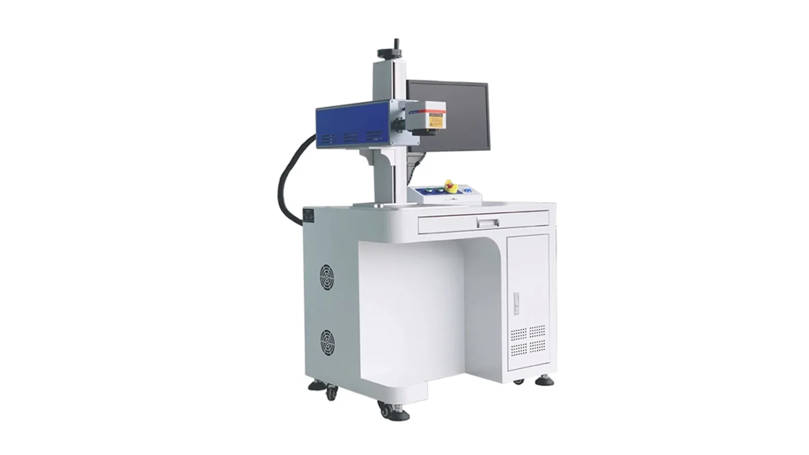
Do not choose the machine from fabric name or rated wattage alone. The accepted mark, workpiece size, handling method and real cycle time should be translated into the CO₂ laser marking machine source, optics, field, workstation and extraction configuration.
| What the test or production study shows | What it drives in the machine |
|---|---|
| Required energy window and accepted cycle time | CO₂ source class and usable operating margin |
| Pattern size and required marking field | Field lens / optics, working distance, table travel or moving-work solution |
| Fine detail and edge requirement | Optical/field-size trade-off, focus control and scan strategy |
| Flat panel, garment, soft/stretch textile or roll | Fixture, tensioning, table, garment support or web-handling design |
| Height variation, seams or uneven workpiece | Z clearance, focus strategy, fixture envelope and loading access |
| Pieces per hour or line speed | Scanner/source combination, loading method and automation level |
| Smoke, odor and residue load | Fume extraction capacity, enclosure and airflow arrangement |
| Operator access and line integration | Enclosure, interlocks, workstation layout, conveyor or online interface |
Next steps
Turn Your Fabric Requirement into a Test Plan
Use the qualification inputs above as your test brief. The goal is to return an accepted fabric-marking process window and the machine configuration needed to reproduce it at the required production rate.
Sample qualification · configuration review · standard and project-based CO₂ marking systems