
Battery module and pack application
Battery Pack Laser Marking for Traceability
Battery pack marking is not only about making a dark code. The real task is to match the laser process to the module or pack surface, keep the code readable without unacceptable surface damage, control positioning on the actual assembly, and connect the verified mark to the correct production record.
Product and workpiece scope
Which Battery Pack Parts Does This Page Cover?
This page covers module-level and complete battery-pack identification on approved external marking surfaces. It is intended for pack housings, module enclosures, selected coated or plastic areas, and laser-markable identification surfaces that must stay traceable through assembly, inspection, shipment and service.
Battery modules
Module enclosures or designated external areas carrying module serials, variants or links to production records.
Pack housings and covers
Metal or coated housing surfaces used for pack-level identification, configuration references or machine-readable codes.
Selected plastic or coated areas
Approved non-metal surfaces where the formulation, coating stack and required result have been validated for laser marking.
Laser-markable labels
Labels or dedicated identification areas used when direct marking on the structural surface is not the preferred route.
Why mark
Why Are Battery Modules and Packs Marked?
The mark gives the physical assembly a durable identity that can be checked against the correct production, inspection or service record.
- Unit identificationKeep module and pack identity attached to the physical assembly through downstream operations.
- Variant controlDistinguish pack configuration, model, production version or approved work order when multiple variants share a line.
- TraceabilityConnect a serial or machine-readable code to manufacturing, inspection, shipment or service data.
- Verification and error controlSupport scanning, wrong-part detection, duplicate prevention and controlled rework where the production system requires it.
What is marked
What Information Is Usually Marked?
The content depends on the manufacturer’s traceability plan, but the laser process must reproduce the required information at the size, location and readability level the production system expects.
- Serial or unique unit IDHuman-readable serials or identifiers used to distinguish a specific module or pack.
- Data Matrix or QR codeMachine-readable content linking the assembly to a controlled data record.
- Part, model or variant codeReferences used to distinguish product family, configuration or manufacturing variant.
- Batch, work-order or service referenceProduction or service information when those fields are part of the approved marking specification.
Result variables
What Determines the Marking Result?
“Battery pack” is not enough information to select a laser. The process window is set by the real surface, code requirement, geometry and production conditions.
- Material and surface
- Base metal or plastic, alloy or formulation, coating type, color, thickness variation, contamination and supplier-lot variation.
- Target mark
- Color change, surface contrast, controlled coating removal, acceptable depth and whether the structural surface must remain essentially unchanged.
- Code requirement
- Text size, Data Matrix or QR cell size, marking area, scanner distance, orientation and required verification method.
- Geometry and focus
- Flat, curved or recessed marking zone, part height, focus tolerance, datum repeatability and scanner access.
- Production condition
- Manual or line loading, takt target, mixed variants, changeover frequency, fixture repeatability and automation level.
- Downstream exposure
- Handling, cleaning, assembly contact, environmental exposure and any durability check defined by the project.
Target result
What Should a Qualified Battery Pack Mark Achieve?
The target is not simply maximum darkness. A usable mark must meet identity, readability, surface and production requirements at the same time.
Correct identity
The content matches the intended module or pack, with no duplicate or wrong-variant association.
Reliable readability
Human-readable text and machine-readable codes remain consistently detectable under the agreed inspection method.
Surface integrity
No unacceptable coating failure, melting, cracking, residue, corrosion concern or damage to a prohibited functional area.
Required durability
The mark remains usable after the handling, cleaning, assembly contact and environmental exposure defined for the project.
Production repeatability
Position, focus, recipe selection and code quality stay within the accepted window across representative parts and normal variation.
Controlled failure response
Unreadable, misplaced or incorrectly bound codes have a defined reject, rework or record-correction path.
Geometry and loading
How Do Pack Size, Marking Position and Loading Affect the System?
Large battery packs can be easy to mark optically but difficult to handle mechanically. The workstation must fit the complete assembly and still place the approved zone at the correct focus and orientation.
Workpiece envelope
Overall length, width, height and weight determine table size, workstation clearance and loading access.
Marking-zone access
Side walls, top covers, recessed areas and nearby structures can limit scanner line of sight or working distance.
Height and focus
Part-height variation and recessed surfaces determine whether fixed focus is sufficient or Z adjustment and a different focus strategy are needed.
Fixture and datum
A repeatable mechanical datum may be enough for stable parts; variable orientation or mixed presentation can justify vision positioning.
Loading method
Manual loading, assisted handling, palletized flow or conveyor integration changes access, cycle structure and guarding needs.
Changeover
Mixed variants may require recipe control, fixture adjustment, recognition checks and a defined first-off verification after changeover.
First-test laser route
Which Laser Should Be Tested First?
The first test should follow the actual marking surface and target result. Do not select a source only because the workpiece is called a battery pack.
| Surface condition | First direction to screen | Compare during testing |
|---|---|---|
| Bare or treated metal | Fiber; evaluate MOPA fiber when broader pulse control is useful | Contrast, depth, edge quality, heat input, readability and surface integrity. |
| Anodized, painted or coated metal | Fiber or MOPA fiber screening according to the required interaction with the coating | Color change versus coating removal, substrate exposure, edge quality, durability and lot variation. |
| Selected plastics | UV is a useful first screen for heat-sensitive or formulation-dependent plastics; other wavelengths remain sample-dependent | Contrast, melting, foaming, cracking, residue, formulation sensitivity and code readability. |
| Laser-markable labels | Use the wavelength range supported by the actual label construction and supplier guidance, then confirm on the installed label | Layer response, edge definition, code quality, adhesion and downstream durability. |
Keep laser screening separate from system integration. Vision, scanners, PLC/MES communication and workstation automation are selected later from positioning, verification, cycle and data requirements.
Failure modes
Where Does Battery Pack Laser Marking Commonly Fail?
Failure diagnosis should start from the observed defect. The same symptom can come from the laser process, surface condition, geometry, positioning or data flow.
Low contrast or unstable code readability
Check surface contamination, coating or formulation variation, focus error, energy density, scan strategy and code geometry. Confirm the fix by rescanning representative parts, not by judging one dark sample.
Coating breakthrough or excessive surface damage
Check whether the process target is color change or controlled removal, then review pulse energy, overlap, passes and coating variation. If the substrate is being exposed unintentionally, the process window is too aggressive or the route is wrong for the required result.
Unwanted melting, excessive foaming, residue or distortion
Separate wavelength/formulation mismatch from excessive heat input. Some controlled foaming can create useful contrast on suitable plastics, so the failure condition is excessive or uncontrolled material response. Compare another wavelength or pulse condition before treating power reduction as the only solution.
Different packs produce different results with the same recipe
Check coating lot, surface cleanliness, part height, focus, fixture datum and supplier variation. A recipe that works only at one nominal condition is not yet a production window.
Code position shifts or part of the code is missing
Check the mechanical datum, fixture seating, part orientation, working distance and whether vision correction is required. Confirm position at the actual production loading repeatability.
Correct mark on the wrong pack or duplicate serial
Review identifier source, part-to-record binding, recipe selection, rework logic and duplicate prevention. This is a traceability failure even if the optical mark itself is perfect.
Production workflow
What Must the Battery Pack Marking Workflow Include?
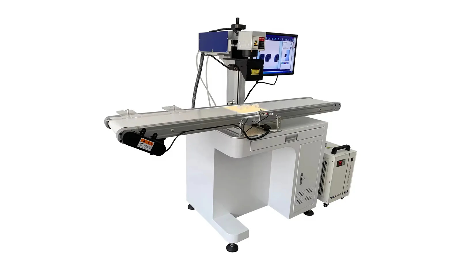
Production control starts before the laser fires. The system must identify the correct assembly, place it repeatably, apply the correct recipe, verify the result and handle failures without breaking traceability.
Identify the assembly
Receive or confirm the module or pack identity and the intended production record before marking.
Confirm variant and recipe
Select the approved marking program for the actual surface, product variant and code requirement.
Load and locate the part
Seat the pack against the defined datum or use vision when presentation variation exceeds fixture repeatability.
Mark the approved zone
Control focus, position, orientation and the validated laser window while protecting keep-out areas.
Verify content and readability
Confirm the marked data, scan result and any required in-station quality check before releasing the assembly.
Release, reject or rework
Pass accepted parts forward. For failed marks, use a predefined rule for re-marking, alternate-zone marking, rejection and record correction so identity is never ambiguous.
Sample qualification
How Should Representative Battery Pack Samples Be Qualified?
Sample testing should establish a repeatable process window and the conditions that break it. A single attractive mark is not enough to specify a production machine.
Freeze the sample matrix
Include representative module or pack variants, material or coating lots, colors, curvature and normal dimensional variation.
Screen the laser route
Compare the relevant wavelength and pulse-control directions against the same target result and prohibited effects.
Establish the process window
Identify a stable parameter range rather than one best-looking point. Record which variables can move without losing acceptance.
Challenge geometry and loading
Repeat the mark at realistic focus variation, part positioning and loading conditions to test fixture and working-distance robustness.
Verify the accepted result
Check identity, code readability, surface integrity and the agreed handling, cleaning or durability exposure using the intended inspection method.
Record failure and rework rules
Define the pass/fail boundary, what can be re-marked, when a new zone is allowed, and when the assembly must be rejected or the traceability record corrected.
Test result to machine configuration
How Do Sample Results Determine the Final Machine Configuration?
The final system should be a consequence of the test. Each confirmed limitation or production requirement should map to a specific laser, optical, mechanical, verification or integration feature.
- Surface response
- Determines the laser source direction and whether wider pulse-width control is needed to reach the required contrast or coating interaction without unacceptable damage.
- Validated process window and takt
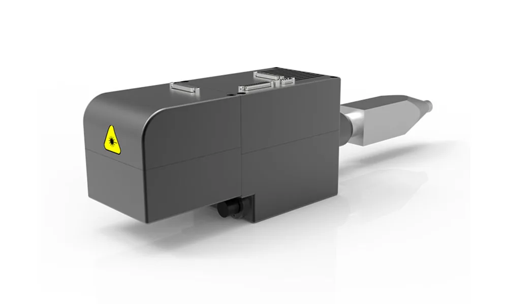
- Map the qualified energy and pulse window, together with the required cycle time, to the source family, required power range, usable pulse-energy capability and, where relevant, adjustable pulse-width range.
- Code size and marking field
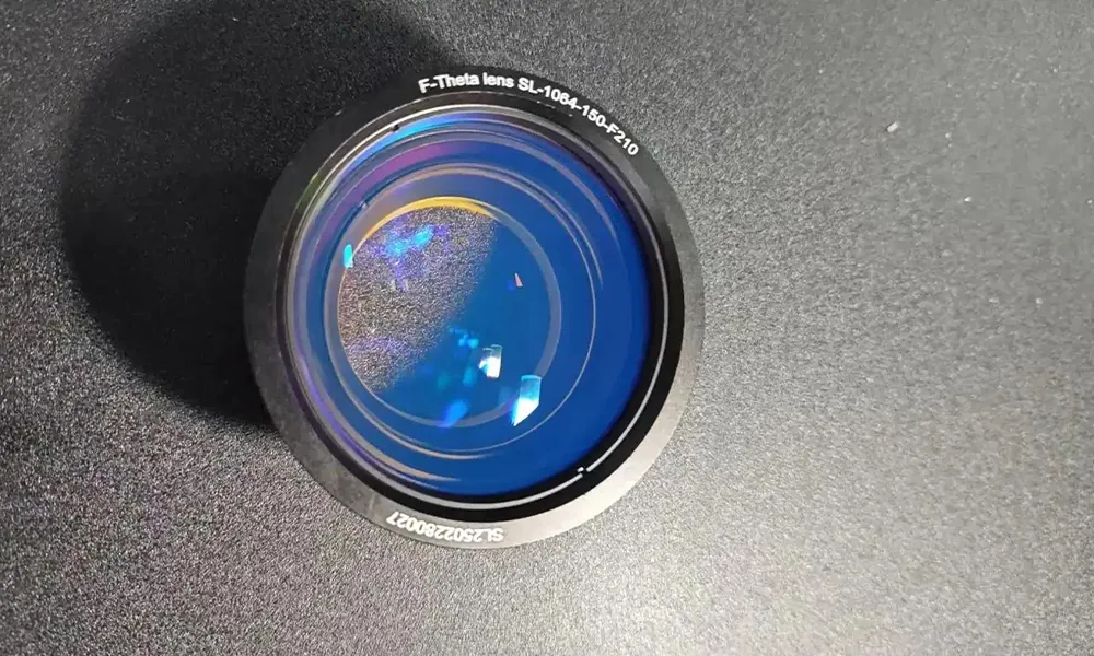
- Drive field-lens selection, marking-field size, working distance and the optical trade-off between field coverage and feature size.
- Height or recessed-zone variation
- Determines fixed-focus feasibility, required Z travel and whether a more advanced focus strategy should be evaluated.
- Pack envelope and weight
- Drive table size, workstation clearance, door or loading access, support method and the practical orientation of the marking head.
- Position variation
- Determines whether a repeatable fixture is sufficient or whether vision recognition and coordinate correction are justified.
- Readability requirement
- Determines whether a scanner or camera should be integrated for code verification and whether the inspection result must be stored.
- Cycle and handling target
- Drive manual, assisted or automated loading architecture, station layout and the amount of motion or line integration required.
- Data and traceability requirement
- Determines the required PLC, database or MES interface, identifier handshake, duplicate prevention and result-return logic.
- Process residue or fume load
- Determines extraction needs and how the marking area should be managed so optics, code quality and the workpiece stay controlled.
Useful project input
What Should You Send for Battery Pack Sample Testing?
The most useful RFQ describes the real surface, target mark, pack geometry, production condition and acceptance method before asking for a machine model.
Move from sample to machine specification
Define the Surface, Result, Geometry and Production Conditions First
Share representative pack parts or drawings, marking content, cycle target and acceptance criteria. The sample result can then be used to determine the laser source, optics, positioning, workstation and verification configuration.