
Cell Housings · Tabs · Traceability · Controlled Mark Zones
Lithium Battery Laser Marking for Cells, Tabs and Safety
Define the exact battery workpiece, surface, mark content, approved marking zone, target result and production requirement before choosing a laser. The right process must create a readable, repeatable mark without introducing unacceptable heat, debris, coating removal or interference with joining, sealing or insulation.
Product & Workpiece Scope
Which Lithium Battery Parts Are Typically Laser Marked?
Lithium battery marking is not one process. A cylindrical steel shell, an aluminum prismatic housing, a copper or aluminum tab and a heat-sensitive insulating film can require different laser directions, fixtures and acceptance checks. Selected pouch-cell tasks are included only when the approved mark is on an external laminate, film, label or another defined non-seal area; sealing edges and other safety-critical pouch features are not treated as general marking zones.
Cylindrical and prismatic cells
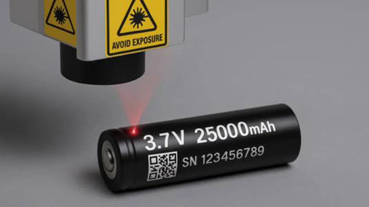
Typical tasks include serial identification, lot information, machine-readable codes and assembly references on an approved housing area.
- Check housing material and coating
- Keep clear of vents, cap assemblies, seams and welds
- Validate code quality on the real curvature or flat face
Small metal parts near joining zones
Tabs and selected cell-level interconnect parts can have narrow mark windows, reflective surfaces and later welding or joining requirements.
- Protect joining and electrical contact areas
- Check discoloration, oxide, burr and surface change
- Treat module- or pack-level busbars as a separate application when their geometry and production process differ from the cell-level task
Sleeves, films, labels and selected polymer parts
Warning, handling and traceability information may appear on heat-sensitive insulation or polymer components. These require their own material-response and durability checks.
- Separate permanent substrate marks from removable labels
- Confirm heat sensitivity and insulation requirements
- Validate abrasion, adhesion or downstream exposure when required
Why Mark
Why Are Lithium Battery Parts Laser Marked?
The marking task is usually driven by traceability, assembly control, machine-readable production data or durable product identification. The reason for marking should be defined before deciding what code to create or which laser to test.
Traceability and production history
Serial, lot or date information can associate the workpiece with production, inspection and downstream records when the data flow is designed for that purpose.
Assembly identification and error prevention
Polarity, orientation, position references and part identifiers can help operators or automated stations distinguish the correct component and assembly direction.
Machine-readable process data
QR or Data Matrix codes can support scanner-based lookup, verification and record association when code size, contrast and reading conditions are validated.
Durable product and handling information
Selected housings, films, sleeves or labels may carry identification, warning or specification information that must remain readable through the defined downstream process and service exposure.
Marking Content
What Is Commonly Marked on Lithium Battery Parts?
| Marking task | What must be defined | What should be checked |
|---|---|---|
| Serial, lot or date code | Format, data source, duplicate rule, location and minimum character size | Correct value, stable position and record association |
| QR or Data Matrix code | Payload, code size, quiet zone, reading device and grade target when required | Readability at production speed and after the defined downstream process |
| Polarity, orientation or handling mark | Approved symbol, contrast expectation and controlled location | Human readability without interfering with safety or functional features |
| Tab or small metal-part identifier | Joining exclusion zone, mark size, orientation and later forming or welding process | Readable mark with acceptable surface and joining condition |
| Warning or specification text | Approved wording, revision, language, usable area and required service life | Complete text and retained readability under the specified exposure |
Result Variables
What Determines the Laser Marking Result on Lithium Battery Parts?
The battery name alone does not determine the process. The result is controlled by the exact material, surface, part state, mark requirement, geometry and production conditions.
| Variable | What to define | Why it changes the result |
|---|---|---|
| Workpiece material | Aluminum, steel, copper, polymer or multilayer construction | Material response changes absorption, contrast, heat input and the suitable starting laser direction. |
| Surface condition | Bare, anodized, painted, plated, coated, sleeved or filmed | The mark may color, modify or remove a surface layer rather than directly mark the base material. |
| Part or cell state | Loose component, pre-assembly part or assembled component under an approved test plan | Heat, debris, access and post-mark checks can change as the component moves closer to final assembly. |
| Mark requirement | Text, serial, symbol, QR, Data Matrix, character size, code size and contrast target | Fine codes and small characters place tighter demands on spot size, focus, field distortion and verification. |
| Geometry and approved zone | Flat, cylindrical, curved, narrow tab area, usable field and keep-out features | Geometry determines positioning, focus strategy, fixture design and whether motion such as rotation is required. |
| Downstream and production conditions | Welding, forming, cleaning, insulation, scan verification, cycle time, changeover and loading method | A visually acceptable mark can still fail if it interferes with later processing or cannot be repeated at production rate. |
Target Result
What Should a Qualified Lithium Battery Mark Achieve?
The target should be defined as an accepted result on the real workpiece, not only as a laser parameter or a visually dark mark.
- Readable and durable: required text, symbol or identifier remains legible after the defined downstream handling, cleaning, abrasion or service exposure where those conditions apply.
- Machine-readable: QR or Data Matrix codes read reliably under the defined production conditions.
- Correctly positioned: the mark remains inside the approved area and clear of controlled features.
- Controlled surface change: contrast is achieved without unacceptable coating removal, debris, distortion or thermal effect.
- Compatible with downstream processing: marking does not create an unacceptable condition for welding, sealing, insulation, cleaning or assembly.
- Repeatable: the accepted result can be reproduced across representative parts, normal part variation and the required cycle time.
Geometry & Handling
How Do Part Geometry and Loading Affect Laser Marking?
Geometry should be defined before laser screening because focus, code distortion, fixture design and handling can decide whether a laboratory sample can become a production process.
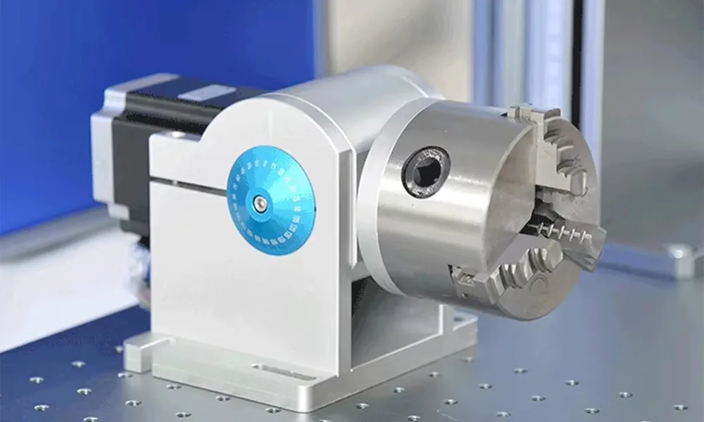
Define diameter, usable mark arc, orientation and whether the code must remain within a limited curved area. Rotation or another controlled presentation method may be required when the usable mark field exceeds the acceptable flat-focus zone.
Confirm which face is marked, reference features, height variation and whether the housing can be located repeatably without approaching seams, welds, terminals or other controlled areas.
The usable area, joining zone, fixture access and part orientation can be more restrictive than the laser itself. Positioning tolerance should be established before final optics and field size are chosen.
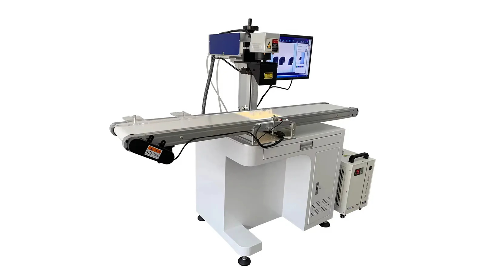
Manual loading, trays, nests, conveyors and automated handling create different requirements for locating features, focus repeatability, changeover and production verification.
Safety & Keep-Out Conditions
Which Battery Features Must Be Protected During Marking?
First-Test Laser Route
Which Laser Should Be Tested First?
Start from the real substrate and surface, then compare only the laser directions that fit the mark requirement, heat sensitivity and production target. The first-test route is a screening direction, not a final machine selection.
| Starting condition | First-test direction | Why it may fit | What decides whether to continue |
|---|---|---|---|
| Bare or selected coated metal housing, metal tab or similar metal component | Fiber / MOPA screening | Common starting direction for many metal surfaces when the required contrast and surface change can be achieved within the accepted heat and geometry limits. | Contrast, coating response, reflectivity, edge quality, thermal effect, code size, curvature and cycle time. |
| Heat-sensitive coating, polymer, sleeve, film or fine-code requirement | UV screening | May provide a smaller affected zone or a better response on selected polymers and sensitive surface systems. | Contrast, insulation or film damage, spot size, throughput, residue and required durability. |
| Selected organic sleeve, film or label that absorbs the wavelength | CO₂ screening | Can fit selected organic marking surfaces; it is not the default route for bare metal battery components. | Thermal change, smoke or residue, edge quality, contrast, material response and production speed. |
Motion and positioning are separate decisions
Rotary motion, fixed fixtures, vision positioning and inline handling should be selected from part geometry, orientation tolerance, loading method and cycle time. They should not be treated as laser types.
Failure Modes
Where Can Lithium Battery Laser Marking Fail?
Failure analysis should connect the visible problem to the variables that can actually distinguish the cause. Do not treat every low-contrast or unreadable result as a simple power problem.
| Observed failure | Likely variables to check | Next validation step |
|---|---|---|
| Low or unstable contrast | Material lot, coating, wavelength response, focus, process window | Compare representative samples and isolate whether the variation follows the surface, focus condition or process setting. |
| QR or Data Matrix reads inconsistently | Module size, distortion, contrast, focus, code placement, reader setup | Inspect code geometry and verify with the actual reading method used in production. |
| Code distorts on a cylindrical surface | Curvature, field size, mark orientation, focus range, part presentation | Test a smaller usable field or controlled rotation and recheck code readability. |
| Excessive coating removal or exposed substrate | Surface-layer thickness, process intensity, number of passes, lot variation | Inspect the marked area and determine whether the accepted result requires color change, controlled removal or a different laser route. |
| Heat discoloration, distortion or damage to film/insulation | Thermal load, wavelength, pulse behavior, dwell or repeated exposure | Reduce thermal loading or compare a more suitable process direction, then repeat the required post-mark checks. |
| Acceptable sample but unstable production result | Fixture repeatability, focus variation, part tolerances, cycle time, lot variation | Repeat the accepted process across representative parts under realistic loading and takt conditions. |
| Residue, particles or contamination remain | Ablation behavior, coating removal, extraction, surrounding geometry | Inspect cleanliness and extraction performance before approving the production process. |
| Mark interferes with joining or electrical contact | Mark location, exclusion zone, surface change, downstream welding/contact requirement | Move or redefine the mark zone and repeat the downstream acceptance check. |
Production Workflow
What Must the Production Marking Workflow Include?
A production marking process must present the correct part, apply the correct data, create the mark, verify the result and handle accepted or rejected parts consistently. These requirements should be defined before production release together with the required takt time and reject logic.
Load
Present the correct part in the required orientation using the defined tray, nest, fixture or line method.
Locate
Confirm the approved mark zone and focus condition using fixture references, sensors or vision when needed.
Assign Data
Load the correct serial, lot, date, symbol or code payload and apply duplicate-prevention rules where required.
Mark
Run the qualified process on the defined surface and within the approved mark area.
Verify
Check position, readability, code quality and the required surface or component condition.
Record / Reject
Associate accepted data with the production record and route failed parts according to the defined reject process.
Cycle time and code density
State the required parts per minute, characters or code modules per part and the available marking window. Scanner speed alone is not the complete production takt.
Environment, extraction and guarding
Review residue, extraction, enclosure, interlocks, operator access and maintenance access for the selected surface and station concept.
Sample Qualification
How Should Representative Lithium Battery Samples Be Qualified?
The sample stage should determine whether the process works on the real part and whether it can be repeated in production. It should not be reduced to making one attractive mark.
Freeze representative samples
Record the exact workpiece, material, coating, part condition, drawing, approved mark zone and keep-out features. Include representative variation when it can affect the result.
Use real artwork and data
Test the actual character size, code size, payload density, symbol and location rather than a generic sample pattern that does not represent production.
Run a controlled comparison
Compare only the suitable laser or process directions while keeping the part condition and acceptance target controlled enough to understand why one result differs from another.
Inspect mark and component
Check position, readability, code verification, surface condition and the post-mark electrical, leak, insulation, dimensional, cleanliness or downstream checks required by the component.
Repeat under realistic handling
Re-run the accepted direction across representative parts using the intended fixture, presentation method and production timing.
Record the accepted process window
Document the accepted workpiece condition, result, inspection method, loading concept and process limits that must remain controlled in production.
Final Machine Configuration
How Do Sample Test Results Determine the Final Machine Configuration?
The final system should be built from what the sample test proves about the surface, mark size, geometry, positioning tolerance, verification method, residue and production rate.
| What the test or application shows | Configuration decision it drives |
|---|---|
| Material and surface response | Fiber / MOPA, UV or CO₂ process direction and the suitable laser source characteristics for the accepted mark. |
| Required contrast and acceptable surface change | Qualified process window and source capability needed to reproduce the result without unacceptable heat, residue or coating removal. |
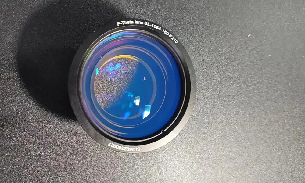
| Small characters, fine Data Matrix or limited usable area | Optics, field lens, marking field and working distance required to balance detail, usable field and access to the workpiece. |
| Cylindrical geometry or mark area around an arc | Rotary motion or another controlled presentation method, plus fixture references and focus strategy. |
| Part height or position variation | Fixture design, focus strategy and possible sensing or height-control requirements. |
| Tight position tolerance or variable orientation | Fixed precision fixture, vision positioning or a combination of both. |
| Production cycle-time requirement | Laser/process speed, loading architecture, changeover method and manual, semi-automatic or inline station concept. |
| Variable serial, lot or database-linked content | Software, code generation, database or MES interface and duplicate-prevention logic. |
| Machine-readable verification requirement | Scanner, camera or verifier, inspection logic and reject handling. |
| Particles, fumes or removed coating | Extraction, filtration and station layout appropriate to the actual marked surface. |
| Operator access and laser-safety requirement | Enclosure, interlocks, guarding and workstation layout. |
FAQ
Lithium Battery Laser Marking Questions
Can an assembled lithium battery cell be laser marked?
Only when the actual component, approved mark zone and required product or process controls have been reviewed. The mark must remain clear of controlled features, and the accepted process may require post-mark checks beyond visual appearance.
What should be included with a lithium battery sample request?
Send the exact part, material and coating information, drawing or photos, approved mark zone, keep-out features, required text or code, code size, reading method, production rate, loading concept and any required post-mark or downstream checks.
Sample Review
Use the sample result to define the machine
Share the exact cell housing, tab or approved battery component together with the surface, mark content, keep-out features, target result, verification method and production requirement. The sample test should then be used to determine the laser, optics, fixture, motion, verification, extraction and automation configuration.