
Laser Coding Applications · Cartons & Labels
Carton and Label Laser Marking
Plan laser coding for cartons, paperboard packaging and selected labels by defining the package construction, code content, target result, marking position, line speed and verification requirement first. CO₂ is often the first route to evaluate for paper and paperboard, while coated, synthetic, foil-bearing or multilayer labels should be routed by the actual surface construction and sample-test result.
Request a Quote See the first-test laser route
- Cartons and secondary packs
- Paper, coated and synthetic labels
- Date, batch and traceability codes
- Moving-line positioning and verification
Application overview
Laser Marking Applications for Cartons and Labels
This page applies when variable information has to be added to a carton, paperboard pack, applied label or label web before or during production. Start with the package type, required code, marking side, reading or scanning requirement, and whether the carton or label will stop or keep moving during marking.
Corrugated Boxes and Folding Cartons
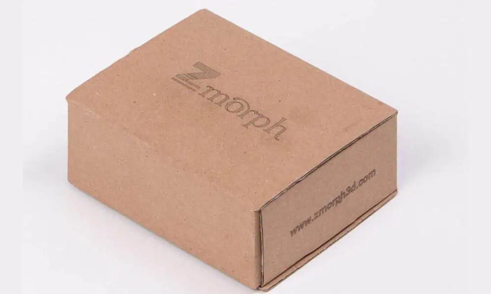
Batch codes, expiry dates, shift codes, product IDs, 1D barcodes or 2D codes on corrugated board, paperboard sleeves, trays and retail cartons. Mark position and carton stability usually decide the integration path.
Paper and Coated Labels
Variable data may be marked on applied labels, label rolls or designated label panels. First confirm where the code must sit and how it will be read; then validate how the label face stock, coating and layer stack respond to the laser.
Inline Coding on Moving Packaging Lines
For moving-line work, the code result depends on more than the laser source. Trigger timing, encoder feedback, product spacing, conveyor vibration, package presentation, verification and safety controls must work together.

Project boundary: This page is for carton and label coding tasks. Bottles, caps, flexible film and other packaging families have different presentation and material behavior and should be evaluated on their own application pages.
Why the code is needed
Why Are Cartons and Labels Coded?
The marking method should be selected only after the business and production purpose of the code is clear. Cartons and labels are usually coded because some information changes by batch, date, product, shipment or production event and therefore cannot be treated as fixed artwork alone.
Identify the Product and Production Batch
Date, lot, batch, shift or SKU information helps operators, warehouses and downstream users distinguish products and production runs.
Connect a Pack to Traceability Data
Serial numbers, Data Matrix codes, QR codes or other identifiers can link the physical package to production, inventory or quality records when the project requires that connection.
Support Scanning and Distribution
Machine-readable codes may be used for warehouse, shipping or downstream scanning, so code location, contrast, module size and reader conditions become part of the application requirement.
Separate the questions: “Why is this package coded?” defines the information requirement. “Why use laser instead of inkjet or a printed label?” is a later technology decision.
What and where
What Is Usually Marked on Cartons and Labels?
Carton and label coding works best when the required content and its exact position are defined before machine selection. A short date code on a plain carton panel, a scannable 2D code on a coated label and a large logistics barcode on corrugated board are different tasks.
| Marking target | Typical content | Application constraint |
|---|---|---|
| Corrugated carton side panel | Batch, date, SKU, simple barcode | Large but absorbent surface; carton skew and panel flatness affect consistency. |
| Retail folding carton | Expiry, lot number, QR / Data Matrix | Smaller panel; printed artwork, varnish or coating may be in the mark window. |
| Paper label on package | Date, batch, serial, QR | Label stock and coating change contrast; position must not interfere with branding or required printed information. |
| Roll-fed label before application | Variable data, serial, traceability code | Web speed, tension, registration, trigger and data handoff define feasibility. |
| Shipping or logistics label | 1D barcode, 2D code, tracking reference | Scanner requirement, quiet zone and downstream read angle become acceptance criteria. |
Technology decision
Laser Marking vs Inkjet and Print-and-Apply Labels
Cartons and labels are commonly coded with laser, inkjet or print-and-apply systems. The right choice depends on required mark durability, consumables, code size, scanner requirements and the surface inside the marking window.
| Requirement | Laser coding | Inkjet carton coding | Print-and-apply labels |
|---|---|---|---|
| No ink or ribbon consumables at the coding head | Strong fit when the substrate gives acceptable contrast at the required speed. | Usually not the reason to choose inkjet. | Still uses label stock and printer supplies. |
| Direct, durable mark on the package surface | Potentially strong fit when substrate response and required durability are validated on samples. | Depends on ink and surface; rub resistance must be checked. | Durability depends on the label material, adhesive and application conditions. |
| Large logistics barcode | Possible on suitable surfaces, but code size and scan performance must be tested. | Common for carton coding; printhead resolution matters. | Common choice when a separate high-contrast barcode label is required. |
| Variable data at high line speed | Feasible when content length and the available mark window are controlled. | Common established method. | Feasible, but label handling, print speed and applicator timing matter. |
| Pre-printed artwork or coated label surface | May remove or alter a coating or printed layer; sample testing is required. | Ink adhesion and drying must be validated. | Often avoids direct interaction with the original package artwork, but adds a label process. |
Laser does not automatically replace inkjet or print-and-apply labeling. Some carton lines use laser for direct date or lot coding while retaining printed labels for large logistics data or other information better served by a label.
Result variables
What Determines the Laser Coding Result?
The words “carton” and “label” are not enough to predict the result. The mark comes from the interaction between the actual surface construction, the code requirement and the production window in which the code has to be produced and verified.
| Variable group | What to record | Why it changes the result |
|---|---|---|
| Package construction | Corrugated board, folding carton, paper label, coated stock, synthetic film or multilayer label. | Different base materials absorb, discolor, ablate or transmit laser energy differently. |
| Surface and artwork | Board color, printed ink, varnish, lacquer, coating, laminate or metallized layer in the code area. | The visible mark may come from the top layer, the substrate below it or an interaction between both. |
| Code requirement | Text, 1D barcode, Data Matrix, QR, code size, module size, quiet zone and required read distance. | Fine machine-readable codes generally place tighter demands on contrast, edge definition and positioning than a simple date code. |
| Production window | Line speed, product pitch, code length, available marking distance and stop-or-move condition. | The code must fit inside the real time and travel window, not only look good on a stationary sample. |
| Package presentation | Distance to the head, panel flatness, skew, orientation, web tension and height variation. | Presentation errors move the code, change focus or reduce repeatability even when the laser parameters are unchanged. |
| Verification environment | Human inspection, scanner model, lighting, read angle, verification station and reject logic. | A code that looks acceptable by eye may still fail the production reader or downstream process. |
Engineering consequence: Changing any one of these groups can change the first-test route, the process window or the final machine configuration even when the package is still described simply as a “carton” or “label.”
Acceptance target
What Result Should You Target?
Define success before choosing the source or comparing samples. The target should describe the finished code under real production conditions, not just whether a visible mark can be made.
- Readable human textDates, lot numbers and identifiers should remain clear against the actual board color, print and coating.
- Reliable machine-readable code1D and 2D codes should meet the project’s real scanner or verification requirement under representative lighting and read angles.
- Stable contrast and edge definitionThe mark should remain distinguishable across normal surface variation without depending on one unusually favorable sample.
- Package integrityThe required contrast should not come at the cost of unacceptable scorching, burn-through, delamination, excessive debris or cosmetic damage.
- Position repeatabilityThe code must stay inside the allowed panel or label window through normal skew, pitch and conveyor variation.
- Required throughputThe accepted result must be achievable at the specified line speed, package spacing and code content.
Geometry and line presentation
Geometry, Positioning and Package Handling
A material may mark well in a sample test and still fail on the line if the package cannot be presented repeatably. Geometry and handling determine whether the laser sees the same marking plane and the same code position every cycle.
| Package condition | Main risk | What to control or test |
|---|---|---|
| Flat carton side panel | Skew, vibration or variable standoff moves the code or changes focus. | Guide rails, stable conveyor presentation, sensor position and allowable height variation. |
| Fold, seam or panel edge near the code | Surface angle or local height change reduces usable marking area. | Move the code window away from unstable geometry or prove the required field and focus tolerance. |
| Applied label on a package | The package, not only the label, determines orientation and repeatability. | Label location tolerance, product skew, package height and trigger reference. |
| Roll-fed or web label | Speed variation, web tension or registration error shifts the code. | Web path, tension, encoder reference, registration mark and available coding distance. |
| Moving carton with variable spacing | Fixed-delay triggering can place codes inconsistently. | Product detection, encoder use where required, pitch variation and the relationship between detection point and mark window. |
Separate two questions: “Can the surface produce the required mark?” is a material/process question. “Can every package receive that mark in the same place?” is a positioning and handling question.
First-test route
Which Laser Route Should Be Tested First?
Do not choose the laser from the word “label” alone. Start from the actual face stock, coating or layer being modified, then test the route against the required code quality and line speed. CO₂ remains a common first route for paper and paperboard, but other constructions need a material-specific decision.
| Construction in the code area | First route to evaluate | What must be proven before selection |
|---|---|---|
| Uncoated paper or corrugated board | CO₂ is usually the first route to evaluate. | Contrast, scorching, fiber damage, code definition and marking time at the target line speed. |
| Printed or coated paperboard carton | CO₂ can still be a strong first test, but the printed or coated layer becomes part of the process. | Whether useful contrast comes from coating/ink change or substrate exposure without unacceptable cosmetic damage. |
| Paper label with coating or varnish | Start from the coating stack; CO₂ is a candidate, not an automatic final choice. | Layer response, debris, heat effect, contrast and whether the adhesive or backing is affected in the real construction. |
| Synthetic polymer label | Select the first test from the actual polymer, pigment and coating. CO₂ may suit some constructions; UV or another wavelength may be worth evaluating when the CO₂ result is unstable or too thermally aggressive. | Contrast mechanism, edge quality, film distortion, layer damage and production-speed stability. |
| Foil-bearing, metallized or multilayer label | Identify the intended target layer first, then compare wavelengths that can modify that layer without damaging the supporting film. | Which layer is being modified, whether underlying film is damaged, and whether the accepted result remains stable at line speed. |
Do not lock the machine family too early: a successful static mark is only the first screen. Final selection also depends on marking time, focus tolerance, motion, verification, fumes and integration requirements.
Failure diagnosis
Common Failure Modes in Carton and Label Laser Coding
A failed code should be diagnosed by symptom. The first question is whether the problem comes from the surface response, the chosen process window, package presentation, timing or verification—not simply whether “more power” is needed.
| Observed problem | Likely cause to investigate | Next confirmation |
|---|---|---|
| Low or inconsistent contrast | Board color, coating, ink or surface batch variation changes the interaction. | Compare representative production samples and separate substrate variation from parameter variation. |
| Dark scorching around the code | Local energy input or scan strategy is too aggressive for the required mark. | Reduce thermal loading and confirm whether readability is still achieved at the target speed. |
| Burn-through, delamination or film distortion | The process is affecting more than the intended surface layer. | Recheck layer construction, focus and process window before increasing speed or power. |
| 2D code looks clear but scans poorly | Module size, quiet zone, edge definition, contrast, lighting or read angle is unsuitable. | Validate with the production reader or agreed verification method rather than visual judgment alone. |
| Code position drifts across the panel | Package skew, trigger timing, encoder reference or conveyor variation is unstable. | Separate the mechanical presentation problem from the laser-marking parameter problem. |
| Characters deform or disappear at higher speed | The code no longer fits the available marking time or travel window. | Measure actual code cycle time against line speed, product pitch and code complexity. |
| Smoke or debris reaches optics or the package | Capture position or airflow is not controlling process emissions effectively. | Review extraction location, airflow path, filtration and lens-contamination behavior on the actual line. |
Production integration
From Package Presentation to Verification and Reject Handling
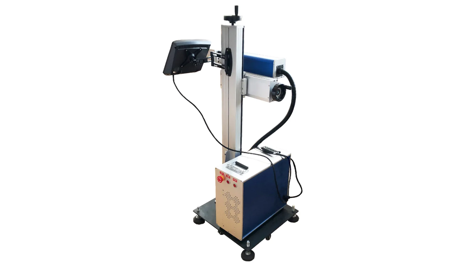
Inline coding is a production sequence, not only a marking event. The package, trigger, variable data, laser cycle, verification and reject decision must remain synchronized at the required throughput.
Stabilize the Package
Guide the carton or label through a repeatable marking plane with the required code area exposed.
Reference the Correct Position
Use the appropriate product sensor, registration reference or encoder input to relate package motion to the mark window.
Resolve the Correct Code Data
Load or receive the correct date, lot, serial or production data before the marking cycle begins.
Fit the Code into the Available Window
Text length, code size, scan strategy and motion must fit the real line speed and package pitch.
Check the Finished Code
Human-readable or machine-readable codes are checked under the agreed production reader, lighting or inspection method.
Act on the Verification Result
Where the line requires automatic inspection, the verification result can feed pass/reject handling and production records through the specified control interface.
Changeover matters: when carton size, label stock, code position or SKU changes, the marking recipe, positioning reference and first-off verification should be rechecked before full production resumes.
Sample acceptance
Sample Testing and Acceptance for Carton and Label Laser Coding
A laser coding system cannot be selected from the word “carton” alone. Test the real package or label construction with the required code and representative line conditions, and define the acceptance criteria before comparing configurations.
- Contrast and readabilityCheck human text and scanner-readable codes on the actual carton color, artwork or label coating.
- Barcode or 2D-code acceptanceVerify module size, quiet zone, edge quality and the agreed scanner or verification condition, not only visual appearance.
- Line-speed fitMeasure marking time against conveyor speed, product pitch, code length and the available mark window.
- Position repeatabilityConfirm the code stays in the required panel or label area despite normal carton skew, belt vibration or web variation.
- Thermal and cosmetic effectCheck scorching, burn-through, delamination, coating debris, odor and any unacceptable appearance change.
- Extraction and guardingReview fume capture, lens contamination, enclosure, interlock and operator-exposure controls for the actual material and line layout.
What to send for testing: representative cartons or labels from the actual line, including pre-printed artwork and coatings, plus line speed, package spacing, mark location, code content, scanner requirement and any PLC / MES or reject-handling needs.
Configuration decision
How Sample-Test Results Determine the Final Machine Configuration
The sample test should end with engineering decisions, not just a photograph of a good mark. Each accepted or failed condition should translate into a configuration choice for the source, optics, motion, package handling, verification, data interface and safety system.
| What the test shows | Configuration implication | What becomes fixed before quotation |
|---|---|---|
| The surface reaches the required contrast without unacceptable damage. | The tested wavelength and process approach remain candidates for the production configuration. | Laser family, tested process window and the material conditions under which the result is valid. |
| The mark is acceptable statically but too slow at target throughput. | Rework code size, scan strategy, source/output choice or production arrangement rather than assuming the static setup can simply be copied to the line. | Target cycle time, code content, line speed and the tested configuration that can meet them. |
| Code position changes with skew, pitch or speed. | Package guides, sensor location, encoder feedback or other positioning controls become part of the system design. | Presentation method, trigger architecture and allowable position variation. |
| Package height or marking plane varies beyond the accepted focus window. | Head position, working distance, line mechanics or height-control strategy must be addressed before finalizing the machine layout. | Working distance, allowable height variation and the chosen mechanical or optical accommodation. |
| The code passes visual inspection but fails the production reader. | Code geometry, contrast, scanner/lighting and verification station need to be treated as one acceptance system. | Reader condition, code specification and pass/fail logic. |
| Variable data comes from a PLC, MES or other production source. | The data interface, message timing, recipe control and confirmation logic enter the delivered system scope. | Required signals, data fields, interface responsibility and error-handling behavior. |
| Smoke, odor or particulate affects the package, optics or work area. | Extraction capacity, capture position, filtration and enclosure design become configuration requirements. | Extraction concept, guarding/interlock scope and the actual material/process conditions used for the assessment. |
Quoting principle: the final configuration should be based on the accepted sample result plus the real production window. If either changes—material, coating, code size, speed, package presentation or verification requirement—the configuration may need to be reviewed again.
Further technical detail
Material and Integration Guides for the Next Level of Detail
Use these pages after the application task above is defined. They provide deeper substrate, machine-family or integration detail without replacing the carton-and-label decision chain on this page.
Paper and Cardboard
Use for deeper questions about paper fiber, board color, charring, contrast and burn-through risk.
Paper & Cardboard Laser MarkingCoated or Synthetic Label Surfaces
Use the coated-plastic guide only when the relevant top layer is a coated plastic construction. For coated paper labels, identify the actual face stock, coating and layer stack first before following a material route.
Coated Plastic Laser MarkingCO₂ Machine Family
Use after the application and sample test support CO₂ as the machine-family direction.
CO₂ Laser Marking MachinesFlying Online Solution
Use when the remaining question is trigger, encoder, conveyor, moving product or line-integration method.
Flying & Online Laser Marking SolutionTraceability Data
Use for serialized codes, PLC / MES handoff, scanner feedback and reject-handling architecture.
Traceability, PLC, MES & Data IntegrationOther Packaging Families
Use beverage, food, cosmetic, pharmaceutical or flexible-film pages when the workpiece family changes.
Packaging & Coding ApplicationsFAQ
Frequently Asked Questions
Can CO₂ lasers code cartons and paper labels?
Often yes, especially for paper and paperboard, and CO₂ is commonly the first route to evaluate. The actual result still depends on board color, print, coating, code quality and line-speed requirements.
How do carton and label materials affect laser coding?
Paper fiber, board color, coatings, varnishes and synthetic label films can change contrast, heat response and debris. For substrate-level behavior and test considerations, see Paper & Cardboard Laser Marking and the related material pages.
Can a carton be coded while moving on a conveyor?
Yes, when the marking cycle, package presentation, trigger or encoder reference, code size and verification requirement can be synchronized with the real line speed and product spacing.
When should we keep inkjet or print-and-apply labels?
Keep or compare those methods when laser contrast is not acceptable, when a separate high-contrast logistics label is required, or when the existing process already meets the project’s cost, speed and verification needs.
Does laser coding replace printed labels?
Not usually as a full replacement. Laser coding can add variable data directly to suitable carton or label surfaces, while printed labels may still carry branding, fixed product information or logistics content.
What information is needed for a quotation?
Provide package photos, material or label-stock details, code content and size, target position, line speed, package spacing, scanner requirement, integration signals and representative samples for testing.
Review Your Carton or Label Coding Project
Zhuorui Laser can review the package construction, code requirement, line condition and sample-test results before recommending the first-test route and final coding configuration.
Carton or label photos · Material and surface/coating notes · Code content, code size and mark location · Required result and scanner condition · Line speed, package pitch and conveyor layout · Trigger, encoder, PLC / MES or reject-handling needs · Sample quantity for marking tests.
Request a Quote OEM & Custom Inquiry Contact Us
Use Request a Quote for standard machine selection; use OEM & Custom Inquiry for online, vision, traceability or non-standard line integration.