
Laser Marking Application — Cable Jackets
Cable Jacket Laser Marking
A workable cable-jacket process must do more than make text visible. The actual jacket compound, color masterbatch, laser-marking additives, diameter, surface condition, line speed, mark interval and downstream wear all affect whether the result is readable, durable and suitable for production.
- Identify the actual jacket compound and surface
- Define the required mark and acceptance result
- Match geometry and line handling to the process
- Use sample results to determine final configuration
Cable Jacket / Product Scope
First confirm what cable surface is actually being marked
This page focuses on identification or coding applied directly to the outer polymer jacket or sheath of a cable. The first engineering step is to define the cable construction, jacket surface and production state rather than treating every black or colored cable as the same material.
- Cable type: power cable, control cable, data or communication cable, harness cable, fiber-optic cable, or another jacketed continuous product.
- Marked layer: confirm whether the laser acts on the outer jacket, an outer coating, a specially formulated marking layer or another exposed surface.
- Product state: extrusion-line cable, reel-fed cable, finished reel, cut length or stationary assembled cable.
- Geometry: record the cable diameter, curvature, available marking width and any height or lateral movement during marking.
- Material identity: record the base polymer or compound, color, masterbatch, additives and supplier or grade information when available.
Do not identify the process from jacket color alone: two jackets that look similar can respond differently because the polymer compound, pigment package, fillers, flame-retardant system, surface treatment or laser-marking additive is different.
Why Mark Cable Jackets?
The mark must support identification, traceability and downstream use
Cable-jacket marking is normally required because people or systems need to identify the cable later, connect it to production records, measure or cut it correctly, or confirm customer-specified information after winding, installation and handling.
Product identification
Keep cable type, size, rating, part number, construction or customer-specific information visible after the product leaves the marking station.
Traceability
Link a cable length or reel to lot, date, shift, serial, production or inspection records when the manufacturing process requires traceable identification.
Length and installation reference
Repeated meter or foot information can support reel handling, cutting, installation and field identification, provided repeat pitch remains correct at the actual line speed.
Customer or destination requirements
Some projects require defined text, symbols, spacing, orientation or code content. The supplied drawing or specification becomes part of the acceptance criteria.
Machine-readable identification
Barcodes or 2D codes may be considered when the cable diameter, code size, contrast and inspection geometry provide a reliable reading window.
Identification that must survive downstream handling
Some cable identification must remain readable after winding, pulling, bundling, installation or other specified handling. In those applications, durability is part of the marking requirement from the start.
What Is Usually Marked?
Mark content must fit the jacket, repeat interval and inspection method
A short identification line, a repeated meter reference and a compact 2D code create different demands on character size, marking time, positioning and verification.
| Task | Possible content | Important inputs | Acceptance focus |
|---|---|---|---|
| Product identification | Part number, size, rating, brand, construction or customer text. | Character height, line length, jacket diameter, position and color contrast. | Legibility after winding, cutting and handling. |
| Length or meter reference | Meter count, foot count, cut reference or repeated text. | Repeat interval, line speed, encoder accuracy, start/stop behavior and restart logic. | Correct repeat pitch and readable content across the run. |
| Batch and production data | Lot, date, shift, reel, serial or recipe-linked information. | Data changeover, message binding, operator workflow and restart behavior. | Correct data through changeover, pause and restart. |
| Barcode or 2D code | Barcode, QR or Data Matrix where jacket geometry and code size allow. | Module size, curvature, orientation, reader distance, lighting and verification method. | Reliable reading under the actual inspection condition. |
| Customer-specified mark | Required wording, symbols, spacing, orientation or traceability layout. | Customer drawing, destination requirements and documented acceptance criteria. | Approval on representative jacket samples and production conditions. |
What Determines the Result?
The marking window is controlled by the jacket compound, mark geometry and production condition
“Black cable,” “PVC jacket” or “30 W laser” is not enough information to predict a production result. The useful test record connects the exact jacket formulation to the required mark, geometry, motion and acceptance criteria.
Base polymer or jacket compound
Record the actual polymer family or compound grade when available. Thermal response, absorption, discoloration and material-removal behavior can differ between formulations that share the same generic material name.
Color masterbatch and pigmentation
Pigment chemistry and loading can change how energy is absorbed and whether the mark becomes light, dark, low-contrast or thermally damaged. Color alone does not identify the correct laser route.
Laser-marking additive identity
If the jacket uses an IR-, NIR- or UV-responsive marking additive or concentrate, record the supplier, product or concentrate identity and dosage when available. That information can materially change the first route worth testing.
Fillers, flame-retardants and coatings
Fillers, flame-retardant systems, coatings and other additive packages can narrow or shift the usable process window. Treat formulation or supplier changes as a reason to recheck the marking recipe.
Surface condition and texture
Smooth, matte, glossy, textured, contaminated or recently processed surfaces can change apparent contrast, edge definition and consistency. Use production-representative surface condition in the test.
Diameter and curvature
Cable diameter changes the available flat-looking marking width, focus variation and code distortion. Small diameters can be especially restrictive for fine text and 2D codes.
Character and code geometry
Character height, stroke width, message length, module size and repeat pitch determine how much marking time and spatial accuracy the process needs.
Line speed and mark frequency
Marking load depends on both product speed and how often the message repeats. A high-speed line with one mark per meter is a different task from the same line with frequent variable codes.
Downstream wear and environment
Winding, guides, pulling, bundling, installation, abrasion, solvents, heat or flex can change a mark that looked acceptable immediately after processing.
Target Result
Define what “good” means before choosing the laser
A darker or deeper mark is not automatically a better cable-jacket result. Acceptance should balance readability, code quality, jacket integrity, durability and repeatability under the real production condition.
Readable contrast
Define whether the mark is inspected visually or by a reader, and under what lighting, distance and orientation.
Character or code integrity
Small text and machine-readable codes need complete strokes, controlled edges and acceptable distortion on the curved surface.
Surface integrity
Avoid unacceptable melting, charring, cracking, excessive groove depth or other damage to the required jacket surface.
Durability after use-related exposure
The mark should remain acceptable after the abrasion, flex, heat, solvent, winding or installation exposure specified for the project.
Position and repeat accuracy
Repeated marks must stay within the required location and interval despite line-speed variation, cable motion and restart events.
Production repeatability
Confirm that an approved sample result can be reproduced across the intended speed range, run duration and product changeovers.
Geometry, Positioning & Cable Handling
Round geometry and continuous motion can be as important as the material
A cable-jacket process must keep the marked surface in a usable focal and positional window while the cable moves through the station. Diameter, cable wander, rotation and line behavior therefore belong in the application review.
- Diameter and curvature: confirm the usable marking width and whether text or code geometry becomes distorted around the cable.
- Height variation: check whether changes in cable position move the surface outside the acceptable focal window.
- Lateral wander: guides and line mechanics must keep the mark within the permitted location across the run.
- Rotation or twist: uncontrolled cable rotation can move the intended mark face away from the marking and inspection position.
- Line presentation: distinguish extrusion-line, reel-fed, cut-length and stationary marking because the synchronization problem is different.
- Changeover: different cable diameters, colors and constructions may require position, focus, guide or recipe adjustments.
First-Test Laser Route
Choose the first laser to test from the jacket formulation and target result
The purpose of the first test is to identify a usable process window, not to declare one wavelength universally correct for a material name. Start from the actual compound, marking mechanism, required contrast and acceptable surface effect.
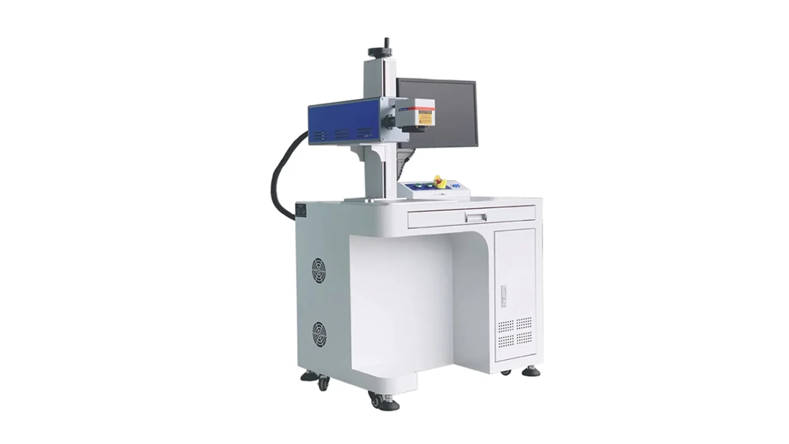
CO₂ route
Evaluate CO₂ when the jacket compound responds usefully to mid-infrared energy and the application can reach the required contrast, edge quality and throughput without unacceptable melting, charring or material removal.
Review CO₂ machine direction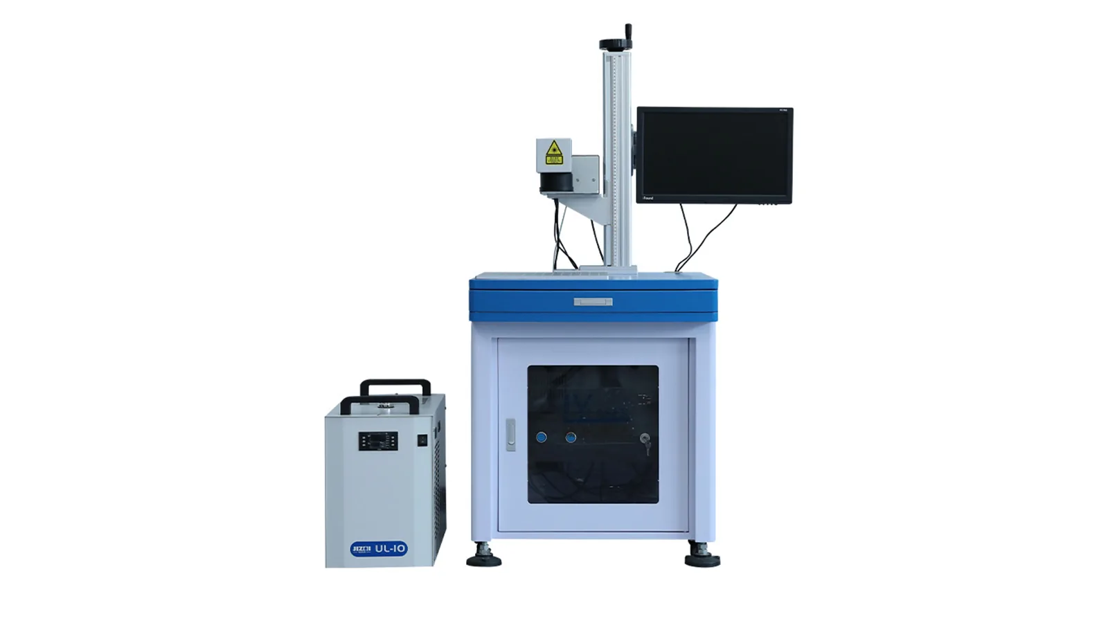
UV route
Evaluate UV when fine detail, a smaller visibly affected area or a different photochemical/thermal response is useful for the actual formulation. Confirm contrast, durability, surface integrity and line-speed capability on real samples.
Review UV machine direction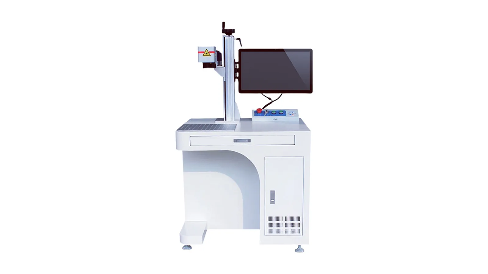
1064 nm fiber / IR-responsive route
Do not assume a standard polymer jacket is suitable for fiber simply because it is dark. However, a jacket specifically compounded with an IR/NIR-responsive laser-marking additive may justify testing a 1064-nm-class fiber route.
Review fiber machine directionFirst-test logic: base polymer + pigmentation + laser-marking additive + target contrast + acceptable surface effect → candidate wavelength → controlled sample test → durability and production verification.
Common Failure Modes
Use the failure symptom to decide what to check next
A failed mark does not automatically mean “more power is needed.” The visible symptom should be connected to formulation, optics, energy density, geometry, motion or downstream wear before changing the process.
| Observed problem | Possible causes to separate | What to check next |
|---|---|---|
| Mark is too light or low-contrast | Wavelength mismatch, pigmentation, additive package, focus, fluence, scan strategy or surface condition. | Verify the actual compound and additive record, then compare controlled parameter windows rather than increasing power blindly. |
| Jacket melts, chars or develops a deep groove | Excess energy density, slow scan, excessive overlap, defocus, thermally sensitive compound or unsuitable marking mechanism. | Reduce thermal loading, check focus and pulse strategy, and compare another candidate route if contrast requires excessive damage. |
| Result changes between colors or production lots | Masterbatch, pigmentation, additive dosage, supplier, formulation revision or surface-process variation. | Separate samples by SKU, color and lot; do not automatically reuse one recipe across changed formulations. |
| Mark looks good initially but wears away | Shallow or weak marking mechanism, poor surface durability, guide contact, winding abrasion, solvent, heat or flex exposure. | Run the defined post-mark wear test and compare the mark before and after the relevant exposure. |
| Text position or repeat interval drifts | Line-speed variation, encoder setup, trigger timing, cable slip, start/stop logic or cable wander. | Check motion signals and physical presentation before changing the laser recipe. |
| 2D code reads in a close-up but fails in production | Curvature, module size, distortion, orientation, cable movement, lighting or reader geometry. | Verify the code on the real cable at the actual inspection position and production speed. |
Production Workflow
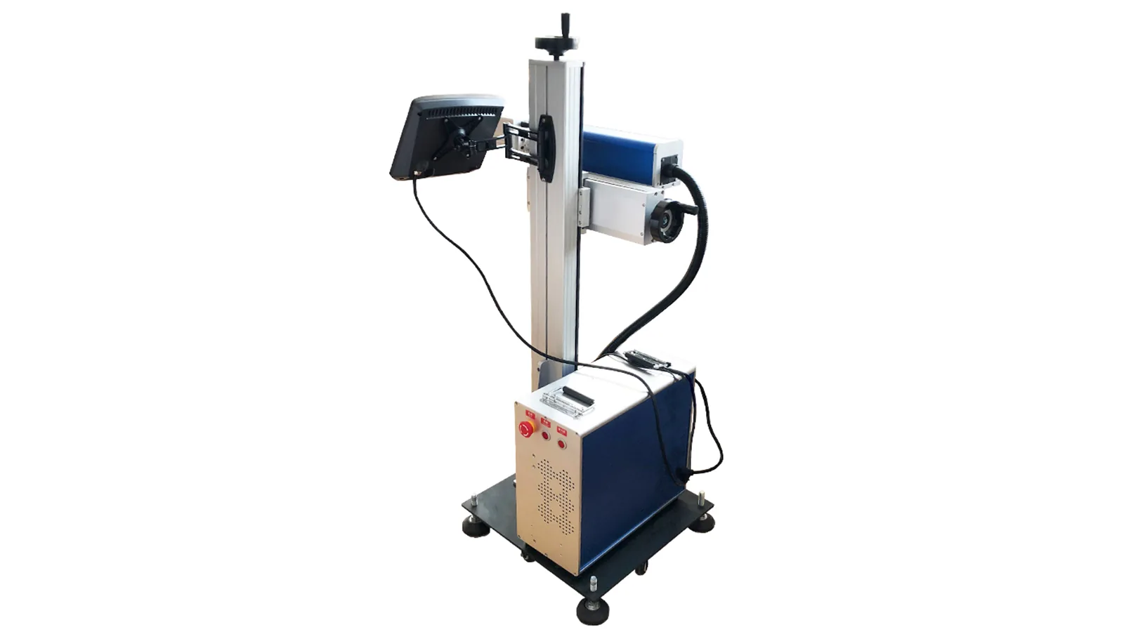
A production-ready process connects cable motion, data, marking and verification
Once a sample process is feasible, the next question is whether the approved result can be produced repeatedly at the real line speed and mark frequency with controlled data and handling.
Sample Acceptance
Approve the jacket before and after the wear that matters
A stationary close-up is only an early feasibility signal. A useful sample test records the exact jacket, compares a controlled process window, evaluates the immediate mark and then repeats inspection after the abrasion, flex, heat, solvent, winding or other exposure required by the project.
1. Record the representative sample
- Base polymer or jacket compound.
- Color and color masterbatch when known.
- Laser-marking additive or concentrate identity and dosage when available.
- Supplier, grade, SKU, lot or formulation revision when available.
- Diameter, wall or outer-layer construction, texture and surface condition.
2. Define the required mark
- Actual text, symbol, barcode or 2D code.
- Character height, stroke width, code module size and message length.
- Position, orientation and repeat interval.
- Visual or reader-based acceptance method.
3. Test a controlled process window
- Compare candidate wavelength or laser route where needed.
- Change controlled process variables instead of altering several unknowns at once.
- Record the parameter set associated with each accepted and rejected sample.
- Stop increasing marking severity when surface damage exceeds the acceptance boundary.
4. Check the mark immediately
- Readability and contrast.
- Character or code integrity.
- Surface damage, melting, charring or excessive depth.
- Position and repeat accuracy.
5. Compare before and after wear
- Photograph or inspect the accepted mark before the required wear test.
- Apply the customer’s required abrasion, rub, flex, heat, solvent, winding or installation exposure.
- Inspect the same acceptance criteria again after exposure.
- Use the applicable cable specification or customer requirement for the pass/fail threshold rather than a universal cycle count.
6. Repeat under production conditions
- Use the intended line-speed range.
- Use the real mark frequency or repeat pitch.
- Check start, stop, restart and changeover behavior.
- Confirm repeatability across a meaningful run rather than one ideal sample.
Acceptance rule: the final test method and threshold should come from the customer’s cable specification, application requirement or agreed inspection method. The page should not invent one universal abrasion, contrast or code threshold for all cable products.
Test Result → Final Machine Configuration
Use the approved sample and production load to define the machine
Final configuration should be the output of the sample and production test. The laser source, optics, synchronization, inspection and machine structure should each answer a measured application requirement.
| Application / test result | Configuration decision | What must be confirmed |
|---|---|---|
| Which wavelength and process window creates acceptable contrast without unacceptable damage | Laser source, wavelength and pulse capability | Approved sample result and usable parameter window on the actual jacket. |
| Required character size, code size and marking width | Lens, marking field, spot-size requirement and optical layout | Smallest feature, field coverage and edge quality across the usable cable surface. |
| Cable diameter, curvature and surface-position variation | Working distance, cable guide, height/position arrangement and possible focus-management strategy | Stable focal and positional window across actual product tolerances. |
| Actual line speed and speed variation | Static or flying architecture, encoder and synchronization method | Readable marks at minimum, nominal and maximum production speed. |
| Mark frequency, repeat pitch and message complexity | Required marking throughput and scan-time margin | Worst-case production load, not only one short demonstration message. |
| Variable lot, serial, meter or order data | Controller, communication and data-interface requirement | Correct message binding at changeover, pause and restart. |
| Barcode or 2D-code verification requirement | Reader, vision or inspection integration | Actual reader geometry, lighting and verification workflow. |
| Fume, odor or residue generated during the approved process | Extraction and enclosure requirement | Process-specific fume capture and production-environment needs. |
| Daily output, shift pattern and continuous run time | Duty-cycle and system architecture | Production volume, hours per shift, number of shifts and required uptime. |
| Number of cable SKUs, diameters, colors and frequent changeovers | Adjustment method, recipe management and guide/fixture strategy | How quickly and reliably the system must move between validated product conditions. |
Do not size the system from line speed alone: production load also depends on message length, smallest feature, repeat interval, variable-data content, required inspection, product mix and duty cycle.
Next Step
Send the jacket, the required mark and the real production conditions
Zhuorui can review the actual cable-jacket sample together with the target mark, durability requirement, geometry and line conditions, then use the test result to narrow the laser and machine configuration.
Prepare for review: representative jacket samples; base polymer or compound; color/masterbatch and laser-marking additive information when available; diameter and surface condition; actual mark content and dimensions; repeat interval; minimum/nominal/maximum line speed; production volume and duty cycle; inspection method; and required abrasion, flex, solvent, heat, winding or installation test.